EP1570872A1 - Tube de transfusion de liquide et ensemble tube de transfusion de liquide - Google Patents
Tube de transfusion de liquide et ensemble tube de transfusion de liquide Download PDFInfo
- Publication number
- EP1570872A1 EP1570872A1 EP03756631A EP03756631A EP1570872A1 EP 1570872 A1 EP1570872 A1 EP 1570872A1 EP 03756631 A EP03756631 A EP 03756631A EP 03756631 A EP03756631 A EP 03756631A EP 1570872 A1 EP1570872 A1 EP 1570872A1
- Authority
- EP
- European Patent Office
- Prior art keywords
- liquid
- connector
- tube
- liquid transfusing
- transfusing
- Prior art date
- Legal status (The legal status is an assumption and is not a legal conclusion. Google has not performed a legal analysis and makes no representation as to the accuracy of the status listed.)
- Ceased
Links
Images


Classifications
-
- A—HUMAN NECESSITIES
- A61—MEDICAL OR VETERINARY SCIENCE; HYGIENE
- A61M—DEVICES FOR INTRODUCING MEDIA INTO, OR ONTO, THE BODY; DEVICES FOR TRANSDUCING BODY MEDIA OR FOR TAKING MEDIA FROM THE BODY; DEVICES FOR PRODUCING OR ENDING SLEEP OR STUPOR
- A61M5/00—Devices for bringing media into the body in a subcutaneous, intra-vascular or intramuscular way; Accessories therefor, e.g. filling or cleaning devices, arm-rests
- A61M5/14—Infusion devices, e.g. infusing by gravity; Blood infusion; Accessories therefor
- A61M5/1407—Infusion of two or more substances
- A61M5/1408—Infusion of two or more substances in parallel, e.g. manifolds, sequencing valves
-
- A—HUMAN NECESSITIES
- A61—MEDICAL OR VETERINARY SCIENCE; HYGIENE
- A61M—DEVICES FOR INTRODUCING MEDIA INTO, OR ONTO, THE BODY; DEVICES FOR TRANSDUCING BODY MEDIA OR FOR TAKING MEDIA FROM THE BODY; DEVICES FOR PRODUCING OR ENDING SLEEP OR STUPOR
- A61M5/00—Devices for bringing media into the body in a subcutaneous, intra-vascular or intramuscular way; Accessories therefor, e.g. filling or cleaning devices, arm-rests
- A61M5/14—Infusion devices, e.g. infusing by gravity; Blood infusion; Accessories therefor
-
- A—HUMAN NECESSITIES
- A61—MEDICAL OR VETERINARY SCIENCE; HYGIENE
- A61M—DEVICES FOR INTRODUCING MEDIA INTO, OR ONTO, THE BODY; DEVICES FOR TRANSDUCING BODY MEDIA OR FOR TAKING MEDIA FROM THE BODY; DEVICES FOR PRODUCING OR ENDING SLEEP OR STUPOR
- A61M39/00—Tubes, tube connectors, tube couplings, valves, access sites or the like, specially adapted for medical use
- A61M39/22—Valves or arrangement of valves
- A61M2039/229—Stopcocks
-
- A—HUMAN NECESSITIES
- A61—MEDICAL OR VETERINARY SCIENCE; HYGIENE
- A61M—DEVICES FOR INTRODUCING MEDIA INTO, OR ONTO, THE BODY; DEVICES FOR TRANSDUCING BODY MEDIA OR FOR TAKING MEDIA FROM THE BODY; DEVICES FOR PRODUCING OR ENDING SLEEP OR STUPOR
- A61M39/00—Tubes, tube connectors, tube couplings, valves, access sites or the like, specially adapted for medical use
- A61M39/22—Valves or arrangement of valves
- A61M39/223—Multiway valves
-
- A—HUMAN NECESSITIES
- A61—MEDICAL OR VETERINARY SCIENCE; HYGIENE
- A61M—DEVICES FOR INTRODUCING MEDIA INTO, OR ONTO, THE BODY; DEVICES FOR TRANSDUCING BODY MEDIA OR FOR TAKING MEDIA FROM THE BODY; DEVICES FOR PRODUCING OR ENDING SLEEP OR STUPOR
- A61M5/00—Devices for bringing media into the body in a subcutaneous, intra-vascular or intramuscular way; Accessories therefor, e.g. filling or cleaning devices, arm-rests
- A61M5/14—Infusion devices, e.g. infusing by gravity; Blood infusion; Accessories therefor
- A61M5/1411—Drip chambers
Definitions
- the present invention relates to a liquid transfusing tube and a liquid transfusing tube set.
- a liquid transfusing tube is provided with a male lure connector at its end part (distal end) on the side of connection to a patient. Therefore, in order to secure a plurality of liquid transfusing routes, it has been necessary to provide the tube on the patient's side with a three-way cock, a multiple-way cock, or the like so as to obtain the condition in which a liquid transfusing route or routes can be additionally provided, i.e., the plurality of liquid transfusing tubes can be connected (see, for example, Japanese Patent Laid-open No. Hei 4-354952).
- liquid transfusing sets having a three-way cock provided at an intermediate part of a liquid transfusing route have been commercialized, the number of liquid transfusing routes required varies depending on the patient or the patient's condition, and the number of liquid transfusing routes, which must preliminarily be prepared, is not known. In view of this, it is a general practice to collect data on the number of liquid transfusing routes used from many patients, calculate an average number of liquid transfusing routes used from the data, and configure the liquid transfusing routes by providing reserve ports capable of connection with liquid transfusing tubes the number, which number is one or two greater than the average number of liquid transfusing tubes used.
- the patients requiring the reserve ports are in many cases those whose conditions are highly liable to change suddenly, and most of the patients to be treated by the liquid transfusing treatment do not require the reserve ports.
- the liquid transfusing sets provided with the reserve ports must be prepared for the small number of patients, which raises the cost of the liquid transfusing sets, or increases the number of kinds of the liquid transfusing sets to be prepared in each hospital, which costs much for stock control, leading to a rise in medical expense.
- liquid transfusing routes may be mis-connected, or dosing speed may be mis-set in again setting the flow rate (setting the dosing speed).
- the needleless connectors are based on the assumption of closed circuits. Therefore, it is impossible to increase the number of liquid transfusing tube connection locations in the course of the liquid transfusing route. In the situation where the number of the connection locations is insufficient, it is necessary to adopt a use method in which the portion on the distal end of the liquid transfusing route provided with the needleless connector is opened and which considerably impairs the characteristic feature of connecting the liquid fusing tubes while maintaining the cleanliness in a closed circuit.
- the present invention has an object of providing a liquid transfusing tube and a liquid transfusing tube set in which a liquid transfusing line (liquid transfusing route) can be extended readily and quickly.
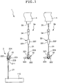
- Fig. 1 is a plan view showing a first embodiment of the liquid transfusing tube set according to the present invention
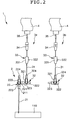
- Fig. 2 is a plan view showing the condition where one of liquid transfusing tubes of the liquid transfusing tube set shown in Fig. 1 is connected
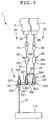
- Fig. 3 is a plan view showing the condition where each of the liquid transfusing tubes of the liquid transfusing tube set shown in Fig. 1 is connected.
- the side of the blood vessel of the patient in the figures will be referred to as “the distal end”, and the side of the blood bag will be referred to as “the proximal end”.
- the liquid transfusing tube set (liquid transfusing set) 1 shown in these figures is an apparatus (set) for injecting (dosing) a liquid (transfusion) into a living body (patient).
- the transfusion includes all the liquids, which can be dosed into the living body, such as chemical liquids, correction electrolyte liquids, physiological saline, etc.
- the kind of the chemical in the chemical liquid is not particularly limited, and examples of the chemical include sedative, intravenous anesthetic, narcotic analgesic, local anesthetic, antidepolarizing muscle relaxant, vasopressor, hypotensive agent, coronary vasodilator, diuretic, antiarrhythmic agent, bronchodialator, hemostatic, vitamin agent, antibiotic drug, and lipid emulsion.
- the liquid transfusing tube set 1 has a liquid dosing part 2 for dosing a patient with the transfusion, and a plurality of liquid transfusing tubes (in this embodiment, two liquid transfusing tubes 3a and 3b) which can be connected to the liquid dosing part through a connector.
- a liquid dosing part 2 for dosing a patient with the transfusion
- a plurality of liquid transfusing tubes in this embodiment, two liquid transfusing tubes 3a and 3b
- the liquid dosing part 2 has an indwelling needle or catheter (in this embodiment, an indwelling needle 21) permitted to indwell in a blood vessel 110 of the patient, and a liquid dosing part side connector 22 connected to a proximal end of the indwelling needle or catheter (in this embodiment, the indwelling needle 21).
- the material constituting the indwelling needle 21 is preferably a flexible polymer material, and examples thereof include thermoplastic resins such as polyolefins such as polyethylene, polypropylene, etc., polyesters, and polyurethanes.
- a tube not shown may be provided between the indwelling needle 21 (or catheter) and the liquid dosing part side connector 22 so as to connect the indwelling needle 21 (or catheter) and the liquid dosing part side connector 22 to each other through the tube.
- the liquid dosing part side connector 22 may be provided at an end part of the tube, or may be provided in the course of the tube.
- the liquid dosing part side connector 22 is not particularly limited inasmuch as it has a female connector or a male connector connectable to a male connector 323 or a female connector 322 of a connector 32 of liquid transfusing tubes 3a, 3b, which will be described later.
- a three-way cock is used as the liquid dosing part side connector 22.
- the liquid dosing part side connector 22 has two female connectors 221, 222, a male connector 223, and an operating lever (operating part) 224, and is so configured that a communication pattern between the inner cavity of the female connector 221, the inner cavity of the female connector 222, and the inner cavity of the male connector 223 can be selected by the operating lever 224 (the liquid dosing part side connector 22 has a channel changeover function for changing over the channel).
- the liquid dosing part side connector 22 is so configured that the operating lever 224 can be moved to each of four positions, i.e., the position of the female connector 221, the position of the female connector 222, the position of the male connector 223, and a position where no connector is present (in Fig. 1, the position where the operating lever 224 is directed in the sense opposite to the male connector 221).
- the operating lever is moved to the position of the female connector 221
- the inner cavity of the female connector 222 and the inner cavity of the male connector 223 are communicated with each other.
- the operating lever 224 is moved to the position of the female connector 222, the inner cavity of the female connector 221 and the inner cavity of the male connector 223 are communicated with each other.
- the axis of the male connector 223 and the axis of the female connector 222 coincide substantially with each other, and the axis of the female connector 221 is substantially orthogonal to these axes.
- the male connector 223 and the female connector 222 are substantially coaxial with each other and are directed in opposite senses, whereas the female connector 221 is set in a direction substantially orthogonal to the male connector 223 and the female connector 222.
- the female connectors 221 and 222 are so shaped as to be capable of liquid-tight connection with a male connector 323 of a connector 32 of a liquid transfusing tubes 3a or 3b, which will be described later.
- a female connector 322 of the connector 32 of the liquid transfusing tube 3a or 3b may be connected to the liquid dosing part side connector 22.
- both the male connector 323 and the female connector 322 of the connector 32 of the liquid transfusing tube 3a or 3b may be capable of connection to the liquid dosing part side connector 22.
- the female connectors 221 and 222 of the liquid dosing part side connector 22 are replaced by male connectors, which are so shaped as to be capable of liquid-tight connection with the female connector 322 of the connector 32 of the liquid transfusing tube 3a or 3b.
- both the male connector 323 and the female connector 322 of the connector 32 of the liquid transfusing tube 3a or 3b can be connected to the liquid dosing part side connector 22, for example, one of the male connectors 221 and 222 of the liquid dosing part side connector 22 is replaced by a male connector, which is so shaped as to be capable of liquid-tight connection to the female connector 322 of the connector 32 of the liquid transfusing tube 3a or 3b.
- the indwelling needle 21 has an outlet port 211 at its proximal end.
- the male connector 223 of the liquid dosing part side connector 22 is in liquid-tight connection with the outlet port 211.
- liquid transfusing tubes 3a and 3b will be described below. Since the liquid transfusing tube 3a and the liquid transfusing tube 3b are configured in the same manner, one of them, i.e., the liquid transfusing tube 3a will be described as a representative of them.
- the liquid transfusing tube 3a includes a tube 31, a connector (branch tube) 32, and a bottle needle 35.
- the tube 31 is flexible and constitutes the liquid transfusing channel.
- the connector (branch tube) 32 is provided at one end part (distal end) of the tube 31 and has a male connector and a female connector.
- the bottle needle 35 has a sharp needle tip and is provided on the other side (in this embodiment, at the other end part [proximal end]) of the tube 31 so as to function as a connection part to be connected to the side of a liquid transfusing bag (liquid transfusing container) (containing part) 4 containing the liquid being transfused.
- a roller klemme (roller type klemme) 33 and a drip tube 34 are provided as flow rate regulating means for regulating the flow rate of the transfusion.
- a predetermined transfusion is contained in the liquid transfusing bag 4.
- the bottle needle 35 pierces (punctures) a plug (rubber plug) of the liquid transfusing bag 4
- the liquid transfusing bag 4 and the liquid transfusing tube 3a are connected to each other through the bottle needle 35, resulting in the condition where the transfusion can be supplied from the liquid transfusing bag 4 to the side of the liquid transfusing tube 3a.
- the drip tube 34 is disposed in the vicinity of the bottle needle 35.
- the drip tube 34 makes it possible to visually check the flow rate of the transfusion.
- the roller klemme 33 is disposed between the connector 32 and the drip tube 34.
- the roller klemme 33 is composed of a klemme main body 331, and a roller (operating part) 332 disposed to be movable relative to the klemme main body 331.
- the tube 31 is clamped between the outer peripheral surface of the roller 332 and a bottom surface (inclined surface) inclined at a predetermined angle against the klemme main body 331, and the roller 332 is moved relative to the klemme main body 331, whereby the degree of clamping the tube 31 is varied, and the flow rate of the transfusion is thereby regulated.
- the roller 332 With the roller 332 moved in a predetermined direction, the degree of clamping the tube 31 is enhanced, and the flow rate of the transfusion is reduced. When the roller 332 is moved to the utmost, the inner cavity of the tube 31 is occluded, so that the liquid being transfused will not flow.
- the connector 32 is not particularly limited inasmuch as it includes a male connector and a female connector; in this embodiment, a three-way cock is used as the connector 32.
- the connector 32 includes two female connectors 321, 322, a male connector 323, and an operating lever (operating part) 324, and the communication pattern among the inner cavity of the female connector 321, the inner cavity of the female connector 322, and the inner cavity of the male connector 323 can be selectively obtained by means of the operating lever 324 (thus, the connector 32 has a channel changeover function for changing over the channel).
- the connector 32 is so configured that the operating lever 324 can be moved to the four positions, i.e., the position of the female connector 321, the position of the female connector 322, the position of the male connector 323, and the position where no connector is present (the position where the operating lever 324 is set in the sense opposite to the female connector 321 in Fig. 1).
- the operating lever 324 is moved to the position of the female connector 321, the inner cavity of the female connector 322 and the inner cavity of the male connector 323 are communicated with each other.
- the operating lever 324 is moved to the position of the female connector 322, the inner cavity of the female connector 321 and the inner cavity of the male connector 323 are communicated with each other.
- the axis of the male connector 323 and the axis of the female connector 322 substantially coincide with each other, and the axis of the female connector 321 is substantially orthogonal to these axes.
- the male connector 323 and the female connector 322 are substantially coaxial with each other and are directed in opposite senses, and the female connector 321 is set in a direction substantially perpendicular to the male connector 323 and the female connector 322.
- the tube 31 is provided at its distal end with a male connector, which is not shown, and the male connector is in liquid-tight connection to the female connector 321 of the connector 32. Incidentally, the distal end of the tube 31 may be joined directly to the female connector 321.
- the male connector 323 of the connector 32 is so shaped as to be capable of liquid-tight connection with another female connector having the same shape as that of the female connector 322.
- the female connector 322 of the connector 32 is so shaped as to be capable of liquid-tight connection to another male connector having the same shape as that of the male connector 323.
- the connector 32 of any liquid transfusing tube can be connected to the connector 32 of another liquid transfusing tube (any number of connectors 32 can be connected).
- the connector 32 is the three-way cock in this embodiment, in the present invention the connector 32 is not limited to the three-way cock inasmuch as it is a connector having a male connector and a female connector; for example, a connector not having the function of changing over the channel, such as a needleless connector having a male connector and a female connector, may be adopted as the connector 32.
- the material constituting the tube 31 may be any of a wide range of materials conventionally used for medical tubes, and specific examples of the material include soft polyvinyl chloride, ethylene-vinyl acetate copolymer, polybutadiene, etc., and materials based on these polymers.
- liquid transfusing tube 3a is used as a first liquid transfusing line (first liquid transfusing route) for dosing a transfusion into a patient, i.e., principally as a liquid transfusing tube for flow therethrough of a fundamental liquid or the like
- liquid transfusing tube 3b is used as a second liquid transfusing line (second liquid transfusing route) for dosing a transfusion into the patient, i.e., principally as an auxiliary route, for example, a liquid transfusing tube for flow therethrough of a lipid emulsion, a remedy, an antibiotic drug, or the like.
- a retentive liquid agent for example, is prepared in the liquid transfusing bag 4.
- the bottle needle 35 of the liquid transfusing tube 3a is made to pierce (puncture) a plug (rubber plug) of the liquid transfusing bag 4 in which the transfusion is contained. This ensures that the liquid transfusing bag 4 and the liquid transfusing tube 3a are connected to each other through the bottle needle 35, resulting in the condition where the transfusion can be supplied from the liquid transfusing bag 4 to the side of the liquid transfusing tube 3a.
- the male connector 323 of the connector 32 of the liquid transfusing tube 3a is inserted and fitted into the female connector 221 of the liquid dosing part side connector 22 having its female connector 223 in liquid-tight connection with the outlet port 211 of the indwelling needle 21 left indwelling in a blood vessel (for example, a peripheral vein) 110 of the patient.
- a blood vessel for example, a peripheral vein
- the operating lever 224 of the liquid dosing part side connector 22 is moved to the position of the female connector 222, and the operating lever 324 of the connector 32 of the liquid transfusing tube 3a is moved to the position of the female connector 322.
- the roller klemme 33 of the liquid transfusing tube 3a is operated to regulate the flow rate (dose rate) of the transfusion in the liquid transfusing tube 3a to a prescribed flow rate (prescribed dose rate) of the retentive liquid agent, and the transfusion is dosed.
- the male connector 323 of the connector 32 of the liquid transfusing tube 3a may be connected to the female connector 222 of the liquid dosing part side connector 22.
- the operating lever 224 of the liquid dosing part side connector 22 is moved to the position of the female connector 221, thereby achieving communication between the inner cavity of the female connector 222 and the inner cavity of the male connector 223 of the liquid dosing part side connector 22.
- liquid dosing part side connector 22 may be omitted, and the male connector 323 of the connector 32 of the liquid transfusing tube 3a may be connected to the outlet port 211 of the indwelling needle 21.
- the male connector 323 and the outlet port 211 are shaped for liquid-tight connection with each other.
- the bottle needle 35 of the liquid transfusing tube 3b is made to pierce (puncture) a plug (rubber plug) of the liquid transfusing bag 4 in which the transfusion is contained. This ensures that the liquid transfusing bag 4 and the liquid transfusing tube 3b are connected to each other through the bottle needle 35, resulting in the condition where the transfusion can be supplied from the liquid transfusing bag 4 to the side of the liquid transfusing tube 3b.
- the male connector 323 of the connector 32 of the liquid transfusing tube 3b is inserted and fitted into the female connector 322 of the connector 32 of the liquid transfusing tube 3a. This results in liquid-tight connection between the female connector 322 of the connector 32 of the liquid transfusing tube 3a and the male connector 323 of the connector 32 of the liquid transfusing tube 3b.
- the operating lever 324 of the connector 32 of the liquid transfusing tube 3b is moved to the position of the female connector 322. This makes communication between the inner cavity of the female connector 321 and the inner cavity of the male connector 323, of the connector 32 of the liquid transfusing tube 3b.
- the operating lever 324 of the connector 32 of the liquid transfusing tube 3a is moved to the position where no connector is present (the position where the operating lever 324 is set in the sense opposite to the female connector 321 in Fig. 3).
- the roller klemme 33 of the liquid transfusing tube 3b is operated to regulate the flow rate (dose rate) of the transfusion in the liquid transfusing tube 3b to a designated flow rate (designated dose rate) of an antibiotic drug, and the transfusion is dosed.
- the patient can be dosed (mixedly dosed) with the retentive liquid agent via the liquid transfusing tube 3a and with the physiological saline containing the antibiotic drug dissolved therein via the liquid transfusing tube 3b.
- the male connector 323 of the connector 32 of an other liquid transfusing tube not shown is inserted and fitted into the female connector 322 of the connector 32 of the liquid transfusing tube 3b, in the same manner as above. This results in liquid-tight connection between the female connector 322 of the connector 32 of the liquid transfusing tube 3b and the male connector 323 of the connector 32 of the other liquid transfusing tube.
- the above-described method of using the liquid transfusing tube set 1 is merely one example, which is nonlimitative.
- the liquid may be replenished via the liquid transfusing tube 3b.
- a port (female connector 322) for connection of a liquid transfusing tube is always present, so that the liquid transfusing line (liquid transfusing route) can be extended quickly and assuredly.
- liquid transfusing line for extending the liquid transfusing line, it suffices to insert and fit the male connector 323 of one connector 32 into the female connector 322 of the other connector 32, so that it is possible to extend the liquid transfusing line while dosing the transfusion (for example, dosing a tiny amount of a drug) via the liquid transfusing tube already connected. This makes it possible to obviate the risk of the situation where the symptom of the patient might be changed due to a change in the concentration of the drug in the blood, for example.
- the number of the liquid transfusing tube(s) in the liquid transfusing tube set may be one, or may be three or more.
- the liquid transfusing tubes may all be the same, or may all be different, or some of them may be the same.
- the liquid transfusing tube 3a of the liquid transfusing tube set 1 may be replaced by a liquid transfusing tube 3c.
- a male connector not shown is provided at one end part (distal end) of the tube 31 of the liquid transfusing tube 3c, and the male connector is connected liquid-tight with a female connector 222 of a liquid dosing part side connector 22.
- the distal end of the tube 31 may be joined directly to the female connector 222.
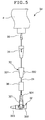
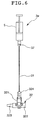
- Figs. 5 and 6 are plan views showing another embodiment of the liquid transfusing tube according to the present invention.
- the liquid transfusing tube 3d shown in Fig. 5 includes, at an intermediate part of a tube 31, a check valve 36 as backflow inhibitive means for permitting the flow from a bottle needle (connection part) 35 to a connector 32 and for inhibiting the flow in the reverse direction.
- the check valve 36 is preferably disposed between the connector 32 and a roller klemme 33. Further, the check valve 36 is preferably disposed in the vicinity of the connector 32.
- the check valve 36 include one that has a valve main body provided therein with a pair of plate-like opening/closing members.
- the opening/closing members are in close contact with each other on the distal end side by elastic forces (recovering forces) and are so tapered as to be spaced farther apart toward the proximal end side. Therefore, in normal condition, the channel in the check valve 36 is closed.
- the liquid exerts a pressure on the outside surfaces of the opening/closing members, acting to urge the opening/closing members into close contact with each other. Therefore, the transfusion would not flow from the distal end side toward the proximal end side.
- the liquid exerts a predetermined pressure on the inside surfaces (taper surfaces) of the opening/closing members, so that the opening/closing members are deformed by the pressure so as to be spaced apart from each other, and the channel in the check valve 36 is opened.
- the transfusion flows from the proximal end side toward the distal end side.
- the check valve 36 can prevent the transfusion from flowing to the upstream side (proximal end side) of the liquid transfusing tube 3d, even when another liquid transfusing tube (for example, a liquid transfusing tube 3e which will be described later) is connected to the connector 32 of the liquid transfusing tube 3d and the transfusion is dosed from the another liquid transfusing tube under a certain pressure; thus, the transfusion can be securely dosed into the patient.
- another liquid transfusing tube for example, a liquid transfusing tube 3e which will be described later
- liquid transfusing tube 3d According to the liquid transfusing tube 3d, the same effects as those of the above-described liquid transfusing tubes 3a, 3b can be obtained.
- the liquid transfusing tube 3e shown in Fig. 6 includes, at the proximal end of a tube 31, a female connector 37, which is connected to the distal end (mouth part) of a syringe (containing part) 5 containing a transfusion, as a connection part for connection with the syringe 5.
- a tiny amount regulation orifice or the like may be provided at an intermediate part of the tube 31, as flow rate regulation means for regulating the flow rate of the transfusion.
- liquid transfusing tube 3e According to the liquid transfusing tube 3e, the same effects as those of the above-mentioned liquid transfusing tubes 3a, 3b can be obtained.
- liquid transfusing tube 3e may include, at an intermediate part of the tube 31, a check valve 36 as backflow inhibitive means for permitting the flow from a connector (connection part) 37 toward the connector 32 and inhibiting the flow in the reverse direction.
- the check valve 36 is preferably disposed in the vicinity of the connector 32.
- check valve 36 the structure and the functions of the check valve 36 are the same as those of the check valve 36 of the above-described liquid transfusing tube 3d shown in Fig. 5, so that the description thereof is omitted.
- the check valve 36 can prevent the transfusion from flowing to the upstream side (proximal end side) of the liquid transfusing tube 3e, even when another liquid transfusing tube is connected to the connector 32 of the liquid transfusing tube 3e and the transfusion is dosed from the another liquid transfusing tube under a certain pressure; thus, the transfusion can be securely dosed into the patient.
- liquid transfusing tubes 3a, 3b, 3d, and 3e can be used either singly or in combination of two or more of them, in the above-described liquid transfusing tube set 1.
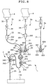
- Fig. 7 is a plan view showing the second embodiment of the liquid transfusing tube set according to the present invention
- Fig. 8 is a plan view showing the condition where one of liquid transfusing tubes of the liquid transfusing tube set shown in Fig. 7 is connected
- Fig. 9 is a plan view showing the condition where each of the liquid transfusing tubes of the liquid transfusing tube set shown in Fig. 7 is connected.
- the liquid transfusing tube set 1 in the second embodiment shown in these figures is the same as the above-described first embodiment, except that a liquid dosing part 2 is different from the above.
- the liquid transfusing tube set 1 includes the liquid dosing part 2, and the same liquid transfusing tubes 3b, 3c, and 3e in the first embodiment described above.
- the liquid dosing part 2 includes an indwelling needle or catheter (in this embodiment, a catheter 23) left indwelling in a blood vessel 110 of a patient, a connector (in this embodiment, a three-way cock) 24 connected to the proximal end of the indwelling needle or catheter (in this embodiment, the catheter 23), a tube 25 which is flexible and constitutes a liquid transfusing channel, a male connector 26 provided at the distal end of the tube 25, a connector (in this embodiment, a three-way cock) 27 provided at the proximal end of the tube 25, a liquid dosing part side connector (in this embodiment, a three-way cock) 28, and a bacteria-removing filter 29.
- an indwelling needle or catheter in this embodiment, a catheter 23
- a connector in this embodiment, a three-way cock
- the indwelling needle or catheter and the connector 24 may be connected to each other through a tube.
- the connector 24 includes two female connectors 241, 242, a male connector 243, and an operating lever (operating part) 244, and the communication pattern among the inner cavity of the female connector 241, the inner cavity of the female connector 242, and the inner cavity of the male connector 243 can be selected by means of the operating lever 244 (thus, the connector 24 has a channel changeover function for changing over the channel).
- the catheter 23 has an outlet port 231 at its proximal end, and the male connector 243 of the connector 24 is in liquid-tight connection with the outlet port 231.
- the male connector 26 provided at the distal end of the tube 25 is in liquid-tight connection with the female connector 241 of the connector 24.
- the liquid dosing part side connector 28 includes three female connectors 281, 282, 283, and an operating lever (operating part) 284, and is so configured that the communication pattern among the inner cavity of the female connector 281, the inner cavity of the female connector 282, and the inner cavity of the female connector 283 can be selected by means of the operating lever 284 (thus, the liquid dosing part side connector 28 has a channel changeover function for changing over the channel).
- the connector 27 includes three female connectors 271, 272, 273, and an operating lever (operating part) 274, and is so configured that the communication pattern among the inner cavity of the female connector 271, the inner cavity of the female connector 272, and the inner cavity of the female connector 273 can be selected by means of the operating lever 274 (thus, the connector 27 has a channel changeover function for changing over the channel).
- a male connector 38 is provided at the distal end of a tube 31 of the liquid transfusing tube 3c, and the male connector 38 is in liquid-tight connection with the female connector 282 of the liquid dosing part side connector 28.
- bacteria-removing filter 29 is provided on the downstream side relative to the liquid dosing part side connector 28, and the connector 27 is provided on the downstream side of the filter 29.
- one end side (downstream side) of the filter 29 is connected liquid-tight to the female connector 272 of the connector 27, and the other end side (upstream side) of the filter 29 is connected liquid-tight to the female connector 283 of the liquid dosing part side connector 28.
- the female connector 271 of the connector 27 constitutes a mixing injection port to which the liquid transfusing tube 3b or 3e or the like is connected.
- the male connector 323 of the connector 32 of the liquid transfusing tube 3b or 3e is connected to the female connector 281 of the liquid dosing part side connector 28 or to the female connector 322 of a connector 32 of an other liquid transfusing tube (3b in Fig. 8) connected to the liquid dosing part side connector 28 in the case where the transfusion may or must be passed through the filter 29.
- the male connector 323 is connected to the male connector 271 of the connector 27 or to the female connector 322 of the connector 32 of the other liquid transfusing tube connected to the connector 27.
- the male connector 323 of the connector 32 of the liquid transfusing tube 3b or 3e or the like is connected to the connector 27 in this embodiment
- the female connector 271 of the connector 27 is replaced by a male connector, which is so shaped as to be capable of liquid-tight connection with the female connector 322 of the connector 32 of the liquid transfusing tube 3b or 3e.
- liquid transfusing tube 3c is used as a first liquid transfusing line (first liquid transfusing route) for dosing a transfusion into a patient, i.e., principally a liquid transfusing tube for flow therethrough of a high-calorie transfusion, a fundamental liquid, or the like
- first liquid transfusing line first liquid transfusing route
- second liquid transfusing route second liquid transfusing route
- the liquid transfusing tube 3e is used as a third liquid transfusing line (third liquid transfusing route) for dosing a transfusion into the patient, i.e., principally as an auxiliary route, for example, as a liquid transfusing tube for flow therethrough of a tiny quantity
- a high calorie transfusion for example, is prepared in a liquid transfusing bag 4.
- a bottle needle 35 of the liquid transfusing tube 3c is made to pierce (puncture) a plug (rubber plug) of the liquid transfusing bag 4 in which the transfusion is contained. This ensures that the liquid transfusing bag 4 and the liquid transfusing tube 3c are connected to each other through the bottle needle 35, resulting in the condition where the transfusion can be supplied from the liquid transfusing bag 4 to the side of the liquid transfusing tube 3c.
- the male connector 38 of the liquid transfusing tube 3c is inserted and fitted into the female connector 282 of the liquid dosing part side connector 28 on the side of the catheter 23 left indwelling in a blood vessel (for example, a central vein or the like) 110 of a patient.
- a blood vessel for example, a central vein or the like
- an operating lever 284 of the liquid dosing part side connector 28 is moved to the position of the female connector 281, whereas an operating lever 274 of the connector 27 is moved to the position of the female connector 271, and an operating lever 244 of the connector 24 is moved to the position of the female connector 241.
- a roller klemme 33 of the liquid transfusing tube 3c is operated so as to regulate the flow rate (dose rate) of the transfusion in the liquid transfusing tube 3c to a prescribed flow rate (prescribed dose rate) of the high-calorie transfusion, and the liquid is dosed.
- a physiological saline containing the antibiotic drug dissolved therein is first prepared in the liquid transfusing bag 4.
- a bottle needle 35 of the liquid transfusing tube 3b is made to pierce (puncture) a plug (rubber plug) of the liquid transfusing bag 4 in which the transfusion is contained. This ensures that the liquid transfusing bag 4 and the liquid transfusing tube 3b are connected to each other through the bottle needle 35, resulting in the condition where the transfusion can be supplied from the liquid transfusing bag 4 to the side of the liquid transfusing tube 3b.
- the male connector 323 of the connector 32 of the liquid transfusing tube 3b is inserted and fitted into the female connector 281 of the liquid dosing part side connector 28. This makes liquid-tight connection between the female connector 281 of the liquid dosing part side connector 28 and the male connector 323 of the connector 32 of the liquid transfusing tube 3b.
- the operating lever 324 of the connector 32 of the liquid transfusing tube 3b is moved to the position of the female connector 322, and the operating lever 284 of the liquid dosing part side connector 28 is moved to the position where no connector is present.
- the inner cavity of the female connector 321 and the inner cavity of the male connector 323 in the connector 32 of the liquid transfusing tube 3b are communicated with each other, and the inner cavity of the female connector 281, the inner cavity of the female connector 282, and the inner cavity of the female connector 283 in the liquid dosing part side connector 28 are all communicated with one another.
- the roller klemme 33 of the liquid transfusing tube 3b is operated to regulate the flow rate (dose rate) of the transfusion in the liquid transfusing tube 3b to a prescribed flow rate (prescribed dose rate) of the antibiotic drug, thereby dosing the transfusion.
- nitroglycerine is sucked and contained into a syringe 5 as shown in Fig. 8.
- the female connector 37 is inserted and fitted into the distal end (mouth part) of the syringe 5. This makes liquid-tight connection between the distal end of the syringe 5 and the female connector 37, resulting in the condition where the transfusion can be supplied from the syringe 5 to the side of the liquid transfusing tube 3e.
- the syringe 5 is set to a syringe pump which is not shown.
- the male connector 323 of the connector 32 of the liquid transfusing tube 3e is inserted and fitted into the female connector 322 of the connector 32 of the liquid transfusing tube 3b. This makes liquid-tight connection between the female connector 322 of the connector 32 of the liquid transfusing tube 3b and the male connector 323 of the connector 32 of the liquid transfusing tube 3e.
- the operating lever 324 of the connector 32 of the liquid transfusing tube 3e is moved to the position of the female connector 322. This results in that the inner cavity of the female connector 321 and the inner cavity of the male connector 323 in the connector 32 of the liquid transfusing tube 3e are communicated with each other.
- the operating lever 324 of the connector 32 of the liquid transfusing tube 3b is moved to the position where no connector is present. This results in that the inner cavity of the female connector 321, the inner cavity of the female connector 322, and the inner cavity of the male connector 323 in the connector 32 of the liquid transfusing tube 3b are all communicated with one another.
- nitroglycerine can be dosed into the patient through the filter 29.
- the operating part on the syringe pump side is operated to regulate the flow rate (dose rate) of the transfusion in the liquid transfusing tube 3e to a prescribed flow rate (prescribed dose rate) of nitroglycerine, and the transfusion is dosed.
- liquid transfusing tube and the liquid transfusing tube set according to the present invention have been described above based on the embodiments shown in the figures, the invention is not limited to the embodiments, and the configurations of the individual parts can be replaced by arbitrary configurations having the same or equivalent functions.
- the present invention may be carried out by combining arbitrary two or more configurations (characteristic features) of the above-described embodiments.
- the liquid transfusing tube set according to the present invention may lack a part of the liquid dosing part, for example, the indwelling needle or catheter or the like. It suffices for the liquid dosing part to have the liquid dosing part side connector (for example, the liquid dosing part may be constituted only of the liquid dosing part side connector).
- the liquid transfusing line (liquid transfusing route) can be extended readily, quickly, and assuredly.
Landscapes
- Health & Medical Sciences (AREA)
- Vascular Medicine (AREA)
- Engineering & Computer Science (AREA)
- Anesthesiology (AREA)
- Biomedical Technology (AREA)
- Heart & Thoracic Surgery (AREA)
- Hematology (AREA)
- Life Sciences & Earth Sciences (AREA)
- Animal Behavior & Ethology (AREA)
- General Health & Medical Sciences (AREA)
- Public Health (AREA)
- Veterinary Medicine (AREA)
- Infusion, Injection, And Reservoir Apparatuses (AREA)
Applications Claiming Priority (3)
| Application Number | Priority Date | Filing Date | Title |
|---|---|---|---|
| JP2002342442A JP2004173844A (ja) | 2002-11-26 | 2002-11-26 | 輸液チューブおよび輸液チューブセット |
| JP2002342442 | 2002-11-26 | ||
| PCT/JP2003/013223 WO2004047887A1 (fr) | 2002-11-26 | 2003-10-16 | Tube de transfusion de liquide et ensemble tube de transfusion de liquide |
Publications (2)
| Publication Number | Publication Date |
|---|---|
| EP1570872A1 true EP1570872A1 (fr) | 2005-09-07 |
| EP1570872A4 EP1570872A4 (fr) | 2008-12-10 |
Family
ID=32375885
Family Applications (1)
| Application Number | Title | Priority Date | Filing Date |
|---|---|---|---|
| EP03756631A Ceased EP1570872A4 (fr) | 2002-11-26 | 2003-10-16 | Tube de transfusion de liquide et ensemble tube de transfusion de liquide |
Country Status (7)
| Country | Link |
|---|---|
| US (1) | US7901386B2 (fr) |
| EP (1) | EP1570872A4 (fr) |
| JP (1) | JP2004173844A (fr) |
| CN (1) | CN100462110C (fr) |
| AU (1) | AU2003302373B2 (fr) |
| HK (1) | HK1082443A1 (fr) |
| WO (1) | WO2004047887A1 (fr) |
Cited By (4)
| Publication number | Priority date | Publication date | Assignee | Title |
|---|---|---|---|---|
| ITAN20100003A1 (it) * | 2010-01-28 | 2011-07-29 | Nacatur Internat Imp Exp S R L | Attrezzatura per la somministrazione di farmaci allo stato liquido in endovena. |
| WO2013087962A1 (fr) * | 2011-12-12 | 2013-06-20 | Antonio Gonzalez Gonzalez | Dispositif fermé pour le remplissage de chambres de goutte-à-goutte dans des dispositifs d'administration de substances cytostatiques, dispositif de sécurité et système de remplissage qui les renferme |
| WO2013107725A1 (fr) * | 2012-01-16 | 2013-07-25 | Sanofi-Aventis Deutschland Gmbh | Trousse de double aveugle destinée à des essais cliniques |
| US10094481B2 (en) | 2012-03-30 | 2018-10-09 | Ge Healthcare Bio-Sciences Ab | Device for delivery of sample fluid |
Families Citing this family (17)
| Publication number | Priority date | Publication date | Assignee | Title |
|---|---|---|---|---|
| JP4872269B2 (ja) * | 2005-08-22 | 2012-02-08 | 株式会社ジェイ・エム・エス | 閉鎖式管状継手 |
| GB0821492D0 (en) * | 2008-11-25 | 2008-12-31 | Team Holdings Uk Ltd | Integrated auto-injector cartridge system |
| JPWO2012002313A1 (ja) * | 2010-06-29 | 2013-08-22 | テルモ株式会社 | 輸液チューブおよび輸液チューブセット |
| CA2987358A1 (fr) | 2011-09-21 | 2013-03-28 | Bayer Healthcare Llc | Pompe multi-fluide continue, systeme et procede d'entrainement et d'actionnement |
| US9427503B2 (en) * | 2013-03-15 | 2016-08-30 | Corvivo Inc. | Cardiotomy suction tube system with multiple tips |
| DE202014103278U1 (de) * | 2014-07-16 | 2015-10-23 | Pfm Medical Ag | Vorrichtung zur dosierten Abgabe einer Infusionsflüssigkeit |
| WO2016112163A1 (fr) | 2015-01-09 | 2016-07-14 | Bayer Healthcare Llc | Système multiple de distribution de fluide avec ensemble jetable à usages multiples et caractéristiques de celui-ci |
| US11357966B2 (en) * | 2015-04-23 | 2022-06-14 | B. Braun Medical Inc. | Compounding device, system, kit, software, and method |
| JP6635736B2 (ja) * | 2015-09-29 | 2020-01-29 | テルモ株式会社 | 輸液セット及びコネクタ |
| WO2017140849A1 (fr) * | 2016-02-19 | 2017-08-24 | Fresenius Kabi Deutschland Gmbh | Unité de soupapes pour une installation de production d'une préparation médicale |
| KR101696741B1 (ko) | 2016-03-31 | 2017-01-16 | (주)메디라인액티브코리아 | 수액세트의 수액튜브 연결구조 |
| WO2018006105A1 (fr) * | 2016-06-30 | 2018-01-04 | K2 Medical (Pty) Limited | Dispositif d'administration de médicament néonatal |
| JP7097018B2 (ja) * | 2018-05-18 | 2022-07-07 | 株式会社ジェイ・エム・エス | 留置針装置 |
| CN109481778A (zh) * | 2018-11-13 | 2019-03-19 | 河北医科大学第三医院 | 用于多袋注射液连接的装置 |
| JP7101136B2 (ja) * | 2019-03-13 | 2022-07-14 | テルモ株式会社 | 流路切替部材及び送液装置 |
| JP6744527B1 (ja) | 2020-04-01 | 2020-08-19 | アットドウス株式会社 | 薬液投与ユニット、薬液投与モジュール、薬液投与装置、及び投薬管理システム |
| CN113262354A (zh) * | 2021-05-14 | 2021-08-17 | 四川大学华西第二医院 | 一种带预充式的pca镇痛泵 |
Citations (3)
| Publication number | Priority date | Publication date | Assignee | Title |
|---|---|---|---|---|
| CA1012431A (en) * | 1972-11-17 | 1977-06-21 | Curt A. Danielsson | Central venous catheter system |
| WO1999034846A2 (fr) * | 1998-01-08 | 1999-07-15 | Loo George D H | Robinet a quatre lumieres et a quatre voies pour injections et perfusions intraveineuses, et pour distribution de liquides et de gaz |
| EP1129682A2 (fr) * | 2000-03-01 | 2001-09-05 | Viktor Krütten | Dispositif d'équilibrage de liquides pour l'alimention entérale de patients |
Family Cites Families (7)
| Publication number | Priority date | Publication date | Assignee | Title |
|---|---|---|---|---|
| US4941875A (en) | 1979-07-18 | 1990-07-17 | Brennan John F | I.V. system for successive administration of two or more solutions at different rates |
| US4447230A (en) * | 1981-08-05 | 1984-05-08 | Quest Medical, Inc. | Intravenous administration set assembly |
| US4734091A (en) * | 1985-02-11 | 1988-03-29 | Atlantic Optical Systems, Inc. | Filtered manifold apparatus and method for ophthalmic irrigation |
| JPH04354952A (ja) * | 1991-05-31 | 1992-12-09 | Terumo Corp | 輸液装置 |
| FR2708702B1 (fr) * | 1993-08-06 | 1995-10-20 | Vygon | Rampe de robinets. |
| DE19915299C1 (de) * | 1999-04-03 | 2000-10-12 | Codan Medizinische Geraete | Kombinationssystem von mehreren medizinischen Geräten zur vollständig intravenösen Anästhesie |
| EP1221320A3 (fr) * | 2000-12-26 | 2002-07-31 | JMS Co., Ltd. | Procédé de composition d'une ligne de perfusion |
-
2002
- 2002-11-26 JP JP2002342442A patent/JP2004173844A/ja active Pending
-
2003
- 2003-10-16 EP EP03756631A patent/EP1570872A4/fr not_active Ceased
- 2003-10-16 US US10/534,364 patent/US7901386B2/en active Active
- 2003-10-16 AU AU2003302373A patent/AU2003302373B2/en not_active Ceased
- 2003-10-16 CN CNB2003801010373A patent/CN100462110C/zh not_active Expired - Fee Related
- 2003-10-16 WO PCT/JP2003/013223 patent/WO2004047887A1/fr active Application Filing
-
2006
- 2006-04-04 HK HK06104105.8A patent/HK1082443A1/xx not_active IP Right Cessation
Patent Citations (3)
| Publication number | Priority date | Publication date | Assignee | Title |
|---|---|---|---|---|
| CA1012431A (en) * | 1972-11-17 | 1977-06-21 | Curt A. Danielsson | Central venous catheter system |
| WO1999034846A2 (fr) * | 1998-01-08 | 1999-07-15 | Loo George D H | Robinet a quatre lumieres et a quatre voies pour injections et perfusions intraveineuses, et pour distribution de liquides et de gaz |
| EP1129682A2 (fr) * | 2000-03-01 | 2001-09-05 | Viktor Krütten | Dispositif d'équilibrage de liquides pour l'alimention entérale de patients |
Non-Patent Citations (1)
| Title |
|---|
| See also references of WO2004047887A1 * |
Cited By (5)
| Publication number | Priority date | Publication date | Assignee | Title |
|---|---|---|---|---|
| ITAN20100003A1 (it) * | 2010-01-28 | 2011-07-29 | Nacatur Internat Imp Exp S R L | Attrezzatura per la somministrazione di farmaci allo stato liquido in endovena. |
| WO2013087962A1 (fr) * | 2011-12-12 | 2013-06-20 | Antonio Gonzalez Gonzalez | Dispositif fermé pour le remplissage de chambres de goutte-à-goutte dans des dispositifs d'administration de substances cytostatiques, dispositif de sécurité et système de remplissage qui les renferme |
| WO2013107725A1 (fr) * | 2012-01-16 | 2013-07-25 | Sanofi-Aventis Deutschland Gmbh | Trousse de double aveugle destinée à des essais cliniques |
| US9861312B2 (en) | 2012-01-16 | 2018-01-09 | Sanofi-Aventis Deutschland Gmbh | Blinding kit for clinical trials |
| US10094481B2 (en) | 2012-03-30 | 2018-10-09 | Ge Healthcare Bio-Sciences Ab | Device for delivery of sample fluid |
Also Published As
| Publication number | Publication date |
|---|---|
| JP2004173844A (ja) | 2004-06-24 |
| CN100462110C (zh) | 2009-02-18 |
| AU2003302373A1 (en) | 2004-06-18 |
| US20060155249A1 (en) | 2006-07-13 |
| WO2004047887A1 (fr) | 2004-06-10 |
| US7901386B2 (en) | 2011-03-08 |
| CN1703253A (zh) | 2005-11-30 |
| EP1570872A4 (fr) | 2008-12-10 |
| AU2003302373B2 (en) | 2009-07-16 |
| HK1082443A1 (en) | 2006-06-09 |
Similar Documents
| Publication | Publication Date | Title |
|---|---|---|
| US7901386B2 (en) | Liquid transfusing tube and liquid transfusing tube set | |
| US6953450B2 (en) | Apparatus and method for administration of IV liquid medication and IV flush solutions | |
| US9089680B2 (en) | Connector | |
| EP0586638B1 (fr) | Recipient d'administration regulee d'un agent benefique | |
| US6158467A (en) | Four-port, four-way, stopcock for intravenous injections and infusions and direction of flow of fluids and gasses | |
| US8267915B2 (en) | Dual well port device | |
| EP0746381B1 (fr) | Dispositif d'acces implantable | |
| US7166084B2 (en) | Blood set priming method and apparatus | |
| EP0246715A2 (fr) | Appareil pour administrer en toute sécurité un remède pour un patient | |
| US20070083156A1 (en) | Subcutaneous needle connection system | |
| US6387069B1 (en) | Blood set priming method and apparatus | |
| KR19980701554A (ko) | 병류 혈액 처리장치 | |
| JP4887394B2 (ja) | 輸液チューブセット | |
| JP5419106B2 (ja) | 薬液セット | |
| JP3266901B2 (ja) | 多段式流量切換装置 | |
| EP0247704A2 (fr) | Récipient pour système d'administration intra-veineux | |
| JP2005334280A (ja) | 輸液チューブおよび輸液チューブセット | |
| JP4584240B2 (ja) | 輸液チューブセット | |
| US6899702B2 (en) | Methods and apparatus for administering intravenous fluids to a patient | |
| EP0435860B1 (fr) | Adapteur pour connecter un flacon pour administrer un remède à un patient | |
| JPH09182791A (ja) | 薬剤投与装置 | |
| JP3525550B2 (ja) | 流体投与或いは採取装置 | |
| WO2008059834A1 (fr) | Elément de fixation temporaire, ensemble connexion et ensemble de tube de perfusion |
Legal Events
| Date | Code | Title | Description |
|---|---|---|---|
| PUAI | Public reference made under article 153(3) epc to a published international application that has entered the european phase |
Free format text: ORIGINAL CODE: 0009012 |
|
| 17P | Request for examination filed |
Effective date: 20050511 |
|
| AK | Designated contracting states |
Kind code of ref document: A1 Designated state(s): AT BE BG CH CY CZ DE DK EE ES FI FR GB GR HU IE IT LI LU MC NL PT RO SE SI SK TR |
|
| AX | Request for extension of the european patent |
Extension state: AL LT LV MK |
|
| DAX | Request for extension of the european patent (deleted) | ||
| A4 | Supplementary search report drawn up and despatched |
Effective date: 20081106 |
|
| 17Q | First examination report despatched |
Effective date: 20110307 |
|
| REG | Reference to a national code |
Ref country code: DE Ref legal event code: R003 |
|
| STAA | Information on the status of an ep patent application or granted ep patent |
Free format text: STATUS: THE APPLICATION HAS BEEN REFUSED |
|
| 18R | Application refused |
Effective date: 20130413 |