EP1570776A2 - Suction/blowing apparatus - Google Patents
Suction/blowing apparatus Download PDFInfo
- Publication number
- EP1570776A2 EP1570776A2 EP05002558A EP05002558A EP1570776A2 EP 1570776 A2 EP1570776 A2 EP 1570776A2 EP 05002558 A EP05002558 A EP 05002558A EP 05002558 A EP05002558 A EP 05002558A EP 1570776 A2 EP1570776 A2 EP 1570776A2
- Authority
- EP
- European Patent Office
- Prior art keywords
- blower
- equipotential bonding
- suction
- motor
- collecting bag
- Prior art date
- Legal status (The legal status is an assumption and is not a legal conclusion. Google has not performed a legal analysis and makes no representation as to the accuracy of the status listed.)
- Withdrawn
Links
Images


Classifications
-
- A—HUMAN NECESSITIES
- A47—FURNITURE; DOMESTIC ARTICLES OR APPLIANCES; COFFEE MILLS; SPICE MILLS; SUCTION CLEANERS IN GENERAL
- A47L—DOMESTIC WASHING OR CLEANING; SUCTION CLEANERS IN GENERAL
- A47L5/00—Structural features of suction cleaners
- A47L5/12—Structural features of suction cleaners with power-driven air-pumps or air-compressors, e.g. driven by motor vehicle engine vacuum
- A47L5/14—Structural features of suction cleaners with power-driven air-pumps or air-compressors, e.g. driven by motor vehicle engine vacuum cleaning by blowing-off, also combined with suction cleaning
-
- A—HUMAN NECESSITIES
- A01—AGRICULTURE; FORESTRY; ANIMAL HUSBANDRY; HUNTING; TRAPPING; FISHING
- A01G—HORTICULTURE; CULTIVATION OF VEGETABLES, FLOWERS, RICE, FRUIT, VINES, HOPS OR SEAWEED; FORESTRY; WATERING
- A01G20/00—Cultivation of turf, lawn or the like; Apparatus or methods therefor
- A01G20/40—Apparatus for cleaning the lawn or grass surface
- A01G20/43—Apparatus for cleaning the lawn or grass surface for sweeping, collecting or disintegrating lawn debris
- A01G20/47—Vacuum or blower devices
-
- A—HUMAN NECESSITIES
- A47—FURNITURE; DOMESTIC ARTICLES OR APPLIANCES; COFFEE MILLS; SPICE MILLS; SUCTION CLEANERS IN GENERAL
- A47L—DOMESTIC WASHING OR CLEANING; SUCTION CLEANERS IN GENERAL
- A47L9/00—Details or accessories of suction cleaners, e.g. mechanical means for controlling the suction or for effecting pulsating action; Storing devices specially adapted to suction cleaners or parts thereof; Carrying-vehicles specially adapted for suction cleaners
- A47L9/10—Filters; Dust separators; Dust removal; Automatic exchange of filters
- A47L9/14—Bags or the like; Rigid filtering receptacles; Attachment of, or closures for, bags or receptacles
-
- A—HUMAN NECESSITIES
- A47—FURNITURE; DOMESTIC ARTICLES OR APPLIANCES; COFFEE MILLS; SPICE MILLS; SUCTION CLEANERS IN GENERAL
- A47L—DOMESTIC WASHING OR CLEANING; SUCTION CLEANERS IN GENERAL
- A47L9/00—Details or accessories of suction cleaners, e.g. mechanical means for controlling the suction or for effecting pulsating action; Storing devices specially adapted to suction cleaners or parts thereof; Carrying-vehicles specially adapted for suction cleaners
- A47L9/28—Installation of the electric equipment, e.g. adaptation or attachment to the suction cleaner; Controlling suction cleaners by electric means
- A47L9/2889—Safety or protection devices or systems, e.g. for prevention of motor over-heating or for protection of the user
-
- H—ELECTRICITY
- H05—ELECTRIC TECHNIQUES NOT OTHERWISE PROVIDED FOR
- H05F—STATIC ELECTRICITY; NATURALLY-OCCURRING ELECTRICITY
- H05F3/00—Carrying-off electrostatic charges
- H05F3/02—Carrying-off electrostatic charges by means of earthing connections
-
- Y—GENERAL TAGGING OF NEW TECHNOLOGICAL DEVELOPMENTS; GENERAL TAGGING OF CROSS-SECTIONAL TECHNOLOGIES SPANNING OVER SEVERAL SECTIONS OF THE IPC; TECHNICAL SUBJECTS COVERED BY FORMER USPC CROSS-REFERENCE ART COLLECTIONS [XRACs] AND DIGESTS
- Y10—TECHNICAL SUBJECTS COVERED BY FORMER USPC
- Y10S—TECHNICAL SUBJECTS COVERED BY FORMER USPC CROSS-REFERENCE ART COLLECTIONS [XRACs] AND DIGESTS
- Y10S55/00—Gas separation
- Y10S55/02—Vacuum cleaner bags
-
- Y—GENERAL TAGGING OF NEW TECHNOLOGICAL DEVELOPMENTS; GENERAL TAGGING OF CROSS-SECTIONAL TECHNOLOGIES SPANNING OVER SEVERAL SECTIONS OF THE IPC; TECHNICAL SUBJECTS COVERED BY FORMER USPC CROSS-REFERENCE ART COLLECTIONS [XRACs] AND DIGESTS
- Y10—TECHNICAL SUBJECTS COVERED BY FORMER USPC
- Y10S—TECHNICAL SUBJECTS COVERED BY FORMER USPC CROSS-REFERENCE ART COLLECTIONS [XRACs] AND DIGESTS
- Y10S55/00—Gas separation
- Y10S55/45—Woven filter mediums
Definitions
- the invention relates to a suction / blower with the features according to the preamble of claim 1.
- Suction pipe can remove dust, leaves or the like from the ground sucked up and over a outflow-side blowpipe in one Blowing bag to be blown.
- a operated by the blower vacuum device for example is arranged in the form of a Venturi announced.
- a suction pipe opens into the venturi. It can Suction of objects through the suction pipe and the Venturi owned and be routed via the blowpipe to the collection bag, without passing through the blower driving the airflow.
- Such Arrangements are particularly for absorbing larger or hard or sensitive objects, for example for Harvesting nuts or the like used.
- suction / blowing devices are, for example, on worn on the back and guided by hand.
- the housing of the blower and in particular the blowpipe are made of plastic, the plastic being opposite as an electrical insulator the drive motor acts.
- blowpipe forms with appropriate blower power a relatively high flow rate. This can be at corresponding atmospheric conditions and during suction of dirt or dust particles laden ambient air in particular due to friction between the particles and the impeller, the blower housing and the blowpipe wall to electrostatic Charges lead.
- the entrained in the air flow electrically charged particles have an electrical potential difference to the surrounding components.
- the particles itself and in particular components of the suction / blowing device develop an electrical potential against each other and also opposite the environment. When touching the suction / blowing device and in particular of the collecting bag, it may be one for the operator unpleasant electrostatic discharge come.
- the invention is based on the object, a suction / blowing device develop the type mentioned in such a way that the Formation of an electrostatic charge is avoided.
- a suction / blower in the inside of the catch bag one with an electrical mass of the suction / blowing device electrically connected equipotential bonding device is arranged. Dust particles or others, entrained in the air flow and electrically in the course of the flow path charged particles lead to the inside when hitting them the collecting bag to its electrostatic charge. About the electrical contacting of the equipotential bonding device the fishing bag with the electrical mass becomes the resulting charge of the collecting bag derived to the mass. in the corresponding dimensions also the potential difference between the catch bag and the environment reduced or eliminated. Of the Fangsack can be easily touched without it to a unpleasant electrostatic discharge between the Fangsack and the operator comes.
- the equipotential bonding device flexible.
- a flexible, for example, a fabric formed collecting bag the shape of the air flow or the Filling level of the collecting bag without mechanical overstress adjust.
- the catch bag including the equipotential bonding device easily collapsible and stowable.
- the equipotential bonding device is expedient as an arrangement electrically conductive, in particular metallic threads executed, wherein the collecting bag advantageously from an electrically conductive threads is made of comprehensive fabric.
- the electrically conductive threads can be the equipotential bonding device train flat and flexible. It can be one Equipotential bonding at any point of the collection bag occur. The formation of individual, island-like places without Equipotential bonding is avoided.
- One the electrically conductive Threads comprehensive tissue can be found in its mechanical and electrical Properties are easily adapted to the requirements. It can be a fiber content with high mechanical strength be chosen, the case of a thin and lightweight Execution of the fabric for a sufficient load capacity provides.
- the one required for a reliable equipotential bonding Content of electrically conductive threads can be arbitrary be set. In particular, an education of the tissue or of the catch bag made thereof completely conductive fibers possible.
- the equipotential bonding device as an electrically conductive, film-like coating formed the fishing bag. It is a reliable, flat charge absorption possible. At the same time, the Foil-like coating desirably for tightness contribute the catch bag.
- the suction / blowing device with an internal combustion engine as a drive motor and the absence of an earth cable of an electrical Power supply is a reliable equipotential bonding inside the device ensured without a charge dissipation would be required by a power cord or the like.
- the equipotential bonding conductor expediently runs on the inside through a blower of the blower, the close to the engine End of equipotential bonding conductor on the inside of the blower in the region of the exhaust manifold, in particular by means of a motor mounting screw is set on the engine. It is also in this area no breakthrough through the blower housing for the equalizing conductor required.
- the equalizing conductor can also in the area of the exhaust manifold for equipotential bonding contribute. About existing in known devices, in the Ausblaskrümmer protruding engine mounting screw is given a reliable ground fault without additional effort.
- the equipotential bonding device the collecting bag with another equipotential bonding device electrically connected in the blowpipe.
- the formation of electrostatic Charges suppressed or at least reduced become. Possibly forming charges can still be derived in the blowpipe, in consequence of which in Fangsack adjusting potential difference is reduced.
- the Potential equalization device in the collection bag is relieved and can reliably equipotent even with very simple design possibly present residual charges.
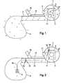
- Fig. 1 shows a schematic block diagram of the essential Components of a hand-held, portable Suction / Blower according to the prior art.
- the blower has a fan 1, which is driven by a motor 2 is.
- the engine 2 is in the illustrated embodiment an internal combustion engine with an indicated carburetor 17. It may also be an electric motor or the like. Be provided.
- the blower 1 is provided with a Ausblaskrümmer 11, to the followed by a blower 1 continuing blow pipe 3.
- the blowpipe 3 opens with its free end into a collecting bag 4. Through a central suction port 27 of the blower 1 and a connected thereto, not shown in detail suction tube can Sucked air flow and the blow pipe 3 in the bag 4 be directed.
- a handle 16 On the outside of the blower tube 3 is a handle 16 with controls for the engine 2 attached. From the controls on Handle 16 leads by way of example a throttle cable 15 to the carburetor 17th The throttle cable 15 is electrically conductive, whereby the handle 16 and the engine 2 with the carburetor 17, the same electrical Have potential. By friction of entrained in the air flow Particles with each other and with the walls of the Ausblaskrümmers 11 and the blowpipe 3 is formed in this area a negative electrostatic sign indicated by minus sign Charge the particles in the air stream. In contrast and also opposite the environment indicates the area of the motor 2, the handle 16 and the housing from the fan 1 by a plus sign indicated positive potential difference.
- the negatively charged dust particles bounce on the inside of the Fangsackes 4, whereby the collecting bag 4 is a negative, indicated by minus sign charge or potential difference receives against the environment.
- the collecting bag 4 is a negative, indicated by minus sign charge or potential difference receives against the environment.
- Fig. 2 shows the development of the arrangement according to the invention
- Fig. 1 in the inside of the blower tube 3 a with the Motor 2 electrically connected equipotential bonding conductor 10 runs.
- the equipotential bonding conductor 10 connects electrically conductive an internal equipotential bonding device 6 of the collecting bag 4 with an electrical ground 5 of the Suction / blowing apparatus.
- the electrical ground 5 is shown in FIG Embodiment formed by a housing 9 of the motor 2. It can also be for example the earthing conductor of an electrical Drive motor or the like. Be provided.
- the equipotential bonding conductor 10 is in the region of its free end 19 by means of a motor mounting screw 12 to the motor 2 electrically determined.
- a further potential equalization device 13 is provided, which via the equipotential bonding conductor 10 with the equipotential bonding device 6 of the fishing bag 4 and with the electrical ground 5 is electrically connected.
- the equipotential bonding conductor 10 is in the embodiment shown with radially protruding Wires of an electrically conductive support spider 18th positioned centrally in the blowpipe 3.
- the equipotential bonding conductor 10 and the support spider 18 have over their entire Length a bare, electrically conductive surface on, over the electric charges can be absorbed.
- the Support spider 18 and the bare potential equalization conductor 10th is the further equipotential bonding device 13 formed.
- air flow is the along the blowpipe 3 resulting electrostatic charge taken over the entire length of the equipotential bonding conductor 10 and about the electrical contact with the engine 2 balanced.
- Another charge absorption from the air flow via the electrically conductive support spider 18.
- Die Support spider 18 takes both electrostatic charges from the airflow over its entire cross section as well from the inner walls of the blower tube 3. The remaining Electric charges are controlled via the equipotential bonding conductor 10 derived to the electrical ground 5.
- Fig. 3 shows in a side view details of the arrangement 2 in the area of the blower 1.
- the blower 1 is in shown embodiment as a radial fan with a spiral Blower housing formed. From the blower housing the inside of a half-shell 21 is shown, in which an indicated Blower wheel 22 about a rotation axis 20 by means of rotation of the motor 2 is drivable.
- the spiral fan housing goes by means of a Ausblaskrümmers 11 in the indicated blowpipe. 3 above.
- the motor 2 is arranged and by means of the end wall of the half-shell 21 thorough engine mounting screws 12 attached.
- the equipotential bonding conductor 10 extends inside through the Ausblaskrümmer 11 of the Blower 1 and inside of the blower 1 in the area of Ausblaskrümmers 11 at the corresponding, arranged there Motor mounting screw 12 with the motor 2 electrically conductive connected.
- Fig. 4 shows a cross-sectional view of the arrangement according to Fig. 3 with a section along the line IV-IV.
- the motor 2 is on the outside of the half-shell 21 by means of the fastening screws 12 fixed, with the fastening screws 12 protrude through the side wall of the half-shell 21.
- the equipotential bonding conductor 10 is located in Area of its end 19 on the inside 23 of the blower. 1 and is there in the region of the exhaust manifold 11 via the engine mounting screw 12 with the outside motor 2 electrically conductive bolted.
- Fig. 5 shows a schematic representation of a fabric 8, from the catch bag 4 (Fig. 2) is made, and by the Equipotential bonding device 6 is formed in the collecting bag 4.
- the fabric 8 is in the illustrated embodiment as a blended fabric with supporting threads 24 and electrically conductive threads 7 educated.
- the electrically conductive threads 7 are metal threads, But also as metallic coated threads, as electrically conductive threads such as carbon fiber or Like. Be executed. Instead of the mixed fabric shown can it may also be expedient to make the fabric 8 entirely of electrical form conductive threads 7.
- Fig. 6 shows a variant of the equipotential bonding device 6 of FIG. 5, in which instead of the flexible fabric 8 a flexible arrangement of a support fabric 25 with a thereon applied film 26 is provided.
- the film 26 with an electric conductive, film-like coating 14 is provided.
- the shown three-layer material with the support fabric 25, the Film 26 and the coating 14 is as a material for formation the collecting bag 4 (Fig. 2) is provided, wherein the film-like Coating 14 to lie on the inside of the collecting bag 4 comes.
- the collecting bag 4 from a to build other material, with the inside of the fishing bag 4 an insert made of a material, for example according to FIGS. 5 and 6 is arranged.
- equipotential bonding device 6 can also be a rigid arrangement, for example in the form of a wireform, a sheet metal strip or the like. Be advantageous.
- the suction / blower device shown can advantageously also be designed in this way be that in the blowpipe 3 a Venturi adopted o. ⁇ . is arranged, in which a suction pipe opens.
- a suction air flow is created in the intake manifold, by means of which nuts, olives or other crops and other, even coarser material collected from the ground and can be directed into the collecting bag 4.
- the Tragluftstrom in the blowpipe 3 are also caused by the suction air flow in the intake manifold electrical potential differences through the equipotential bonding device 6 reliably compensated become.
Abstract
Description
Die Erfindung betrifft ein Saug-/Blasgerät mit den Merkmalen
nach dem Oberbegriff des Anspruchs 1.The invention relates to a suction / blower with the features
according to the preamble of
Bei handgeführten, tragbaren Saug-/Blasgeräten wird mittels eines motorbetriebenen Gebläses ein Luftstrom erzeugt. Mittels eines beispielsweise saugseitig an das Saug-/Blasgerät angeschlossenen Saugrohres kann Staub, Laub oder dgl. vom Boden aufgesaugt und über ein ausströmseitiges Blasrohr in einen Fangsack geblasen werden.In hand-held, portable suction / blower devices by means of a motor-driven blower generates an air flow. through an example of suction connected to the suction / blowing device Suction pipe can remove dust, leaves or the like from the ground sucked up and over a outflow-side blowpipe in one Blowing bag to be blown.
Es sind auch Ausführungsformen bekannt, bei denen im Blasrohr eine durch den Blasstrom betätigte Unterdruckeinrichtung beispielsweise in Form einer Venturieinrichtung angeordnet ist. Ein Saugrohr mündet dabei in die Venturieinrichtung. Es können Gegenstände durch das Saugrohr und die Venturieinrichtung angesaugt und über das Blasrohr zum Fangsack geleitet werden, ohne das den Luftstrom antreibende Gebläse zu passieren. Derartige Anordnungen werden insbesondere zum Aufsaugen größerer bzw. harter oder empfindlicher Gegenstände, beispielsweise zum Ernten von Nüssen oder dgl. eingesetzt. There are also known embodiments in which in the blowpipe a operated by the blower vacuum device, for example is arranged in the form of a Venturieinrichtung. A suction pipe opens into the venturi. It can Suction of objects through the suction pipe and the Venturieinrichtung and be routed via the blowpipe to the collection bag, without passing through the blower driving the airflow. such Arrangements are particularly for absorbing larger or hard or sensitive objects, for example for Harvesting nuts or the like used.
Die vorgenannten Saug-/Blasgeräte werden beispielsweise auf dem Rücken getragen und von Hand geführt. Das Gehäuse des Gebläses und insbesondere das Blasrohr sind aus Kunststoff gefertigt, wobei der Kunststoff als elektrischer Isolator gegenüber dem Antriebsmotor wirkt.The aforementioned suction / blowing devices are, for example, on worn on the back and guided by hand. The housing of the blower and in particular the blowpipe are made of plastic, the plastic being opposite as an electrical insulator the drive motor acts.
Im Blasrohr bildet sich bei entsprechender Gebläseleistung eine relativ hohe Strömungsgeschwindigkeit aus. Diese kann bei entsprechenden atmosphärischen Bedingungen und beim Ansaugen von schmutz- oder staubpartikelbeladener Umgebungsluft insbesondere durch Reibung zwischen den Partikeln und dem Gebläserad, dem Gebläsegehäuse und mit der Blasrohrwand zu elektrostatischen Aufladungen führen. Die im Luftstrom mitgeführten elektrisch geladenen Partikel weisen eine elektrische Potentialdifferenz zu den umgebenden Bauteilen auf. Die Partikel selbst und insbesondere Bauteile des Saug-/Blasgerätes entwickeln ein elektrisches Potential gegeneinander und auch gegenüber der Umgebung. Beim Berühren des Saug-/Blasgerätes und insbesondere des Fangsackes kann es zu einer für die Bedienperson unangenehmen elektrostatischen Entladung kommen.In the blowpipe forms with appropriate blower power a relatively high flow rate. This can be at corresponding atmospheric conditions and during suction of dirt or dust particles laden ambient air in particular due to friction between the particles and the impeller, the blower housing and the blowpipe wall to electrostatic Charges lead. The entrained in the air flow electrically charged particles have an electrical potential difference to the surrounding components. The particles itself and in particular components of the suction / blowing device develop an electrical potential against each other and also opposite the environment. When touching the suction / blowing device and in particular of the collecting bag, it may be one for the operator unpleasant electrostatic discharge come.
Der Erfindung liegt die Aufgabe zugrunde, ein Saug-/Blasgerät der eingangs genannten Gattung derart weiterzubilden, daß die Bildung einer elektrostatischen Aufladung vermieden ist.The invention is based on the object, a suction / blowing device develop the type mentioned in such a way that the Formation of an electrostatic charge is avoided.
Es wird ein Saug-/Blasgerät vorgeschlagen, bei dem innenseitig des Fangsackes eine mit einer elektrischen Masse des Saug-/Blasgerätes elektrisch leitend verbundene Potentialausgleichseinrichtung angeordnet ist. Staubpartikel oder andere, im Luftstrom mitgeführte und im Laufe des Strömungsweges elektrisch aufgeladene Partikel führen beim Auftreffen auf die Innenseite des Fangsackes zu dessen elektrostatischer Aufladung. Über die elektrische Kontaktierung der Potentialausgleichseinrichtung des Fangsackes mit der elektrischen Masse wird die entstehende Ladung des Fangsackes zur Masse abgeleitet. Im entsprechenden Maße wird auch die Potentialdifferenz zwischen dem Fangsack und der Umgebung verringert bzw. aufgehoben. Der Fangsack kann ohne weiteres berührt werden, ohne daß es zu einer unangenehmen elektrostatischen Entladung zwischen dem Fangsack und der Bedienperson kommt.It is proposed a suction / blower, in the inside of the catch bag one with an electrical mass of the suction / blowing device electrically connected equipotential bonding device is arranged. Dust particles or others, entrained in the air flow and electrically in the course of the flow path charged particles lead to the inside when hitting them the collecting bag to its electrostatic charge. About the electrical contacting of the equipotential bonding device the fishing bag with the electrical mass becomes the resulting charge of the collecting bag derived to the mass. in the corresponding dimensions also the potential difference between the catch bag and the environment reduced or eliminated. Of the Fangsack can be easily touched without it to a unpleasant electrostatic discharge between the Fangsack and the operator comes.
In einer vorteilhaften Weiterbildung ist die Potentialausgleichseinrichtung flexibel ausgebildet. Insbesondere in Verbindung mit einem flexiblen, beispielsweise aus einem Gewebe gebildeten Fangsack kann sich die Form dem Luftstrom bzw. dem Füllgrad des Fangsackes ohne mechanische Überbeanspruchung anpassen. Außerhalb des Betriebes ist der Fangsack einschließlich der Potentialausgleichseinrichtung leicht zusammenlegbar und verstaubar.In an advantageous development, the equipotential bonding device flexible. In particular in connection with a flexible, for example, a fabric formed collecting bag, the shape of the air flow or the Filling level of the collecting bag without mechanical overstress adjust. Outside the farm is the catch bag including the equipotential bonding device easily collapsible and stowable.
Die Potentialausgleichseinrichtung ist zweckmäßig als Anordnung elektrisch leitender, insbesondere metallischer Fäden ausgeführt, wobei der Fangsack vorteilhaft aus einem die elektrisch leitenden Fäden umfassenden Gewebe gefertigt ist. Durch die elektrisch leitenden Fäden läßt sich die Potentialausgleichseinrichtung flächig und flexibel ausbilden. Es kann ein Potentialausgleich an jeder beliebigen Stelle des Fangsackes stattfinden. Die Bildung einzelner, inselartiger Stellen ohne Potentialausgleich ist vermieden. Ein die elektrisch leitenden Fäden umfassendes Gewebe kann in seinen mechanischen und elektrischen Eigenschaften leicht den Erfordernissen angepaßt werden. Es kann ein Faseranteil mit hoher mechanischer Belastbarkeit gewählt werden, der bei einer dünnen und leichtgewichtigen Ausführung des Gewebes für eine hinreichende Tragfähigkeit sorgt. Der für einen zuverlässigen Potentialausgleich erforderliche Gehalt an elektrisch leitenden Fäden kann beliebig eingestellt werden. Insbesondere ist eine Ausbildung des Gewebes bzw. des daraus gefertigten Fangsackes vollständig aus leitenden Fasern möglich.The equipotential bonding device is expedient as an arrangement electrically conductive, in particular metallic threads executed, wherein the collecting bag advantageously from an electrically conductive threads is made of comprehensive fabric. By the electrically conductive threads can be the equipotential bonding device train flat and flexible. It can be one Equipotential bonding at any point of the collection bag occur. The formation of individual, island-like places without Equipotential bonding is avoided. One the electrically conductive Threads comprehensive tissue can be found in its mechanical and electrical Properties are easily adapted to the requirements. It can be a fiber content with high mechanical strength be chosen, the case of a thin and lightweight Execution of the fabric for a sufficient load capacity provides. The one required for a reliable equipotential bonding Content of electrically conductive threads can be arbitrary be set. In particular, an education of the tissue or of the catch bag made thereof completely conductive fibers possible.
In einer zweckmäßigen Alternative ist die Potentialausgleichseinrichtung als elektrisch leitende, folienartige Beschichtung des Fangsackes ausgebildet. Es ist eine zuverlässige, flächige Ladungsaufnahme möglich. Gleichzeitig kann die folienartige Beschichtung in erwünschter Weise zur Dichtigkeit des Fangsackes beitragen.In an expedient alternative, the equipotential bonding device as an electrically conductive, film-like coating formed the fishing bag. It is a reliable, flat charge absorption possible. At the same time, the Foil-like coating desirably for tightness contribute the catch bag.
In einer zweckmäßigen Ausbildung ist die elektrische Masse des Saug-/Blasgerätes durch den Motor und insbesondere durch ein Gehäuse des Motors gebildet. Im Zusammenhang mit einer Ausbildung des Saug-/Blasgerätes mit einem Verbrennungsmotor als Antriebsmotor und dem Fehlen eines Massekabels einer elektrischen Stromversorgung ist geräteintern ein zuverlässiger Potentialausgleich sichergestellt, ohne daß eine Ladungsableitung durch ein Netzkabel oder dergleichen erforderlich wäre.In an expedient design, the electrical mass of Suction / Blower by the engine and in particular by a Housing of the engine formed. In connection with an education the suction / blowing device with an internal combustion engine as a drive motor and the absence of an earth cable of an electrical Power supply is a reliable equipotential bonding inside the device ensured without a charge dissipation would be required by a power cord or the like.
Der Potentialausgleichsleiter verläuft zweckmäßig innenseitig durch einen Ausblaskrümmer des Gebläses, wobei das motornahe Ende des Potentialausgleichsleiters innenseitig des Gebläses im Bereich des Ausblaskrümmers insbesondere mittels einer Motorbefestigungsschraube am Motor festgelegt ist. Es ist auch in diesem Bereich kein Durchbruch durch das Gebläsegehäuse für den Ausgleichsleiter erforderlich. Der Ausgleichsleiter kann auch im Bereich des Ausblaskrümmers zum Potentialausgleich beitragen. Über die bei bekannten Geräten vorhandene, in den Ausblaskrümmer hineinragende Motorbefestigungsschraube ist ohne zusätzlichen Aufwand ein zuverlässiger Masseschluß gegeben.The equipotential bonding conductor expediently runs on the inside through a blower of the blower, the close to the engine End of equipotential bonding conductor on the inside of the blower in the region of the exhaust manifold, in particular by means of a motor mounting screw is set on the engine. It is also in this area no breakthrough through the blower housing for the equalizing conductor required. The equalizing conductor can also in the area of the exhaust manifold for equipotential bonding contribute. About existing in known devices, in the Ausblaskrümmer protruding engine mounting screw is given a reliable ground fault without additional effort.
In einer vorteilhaften Weiterbildung ist die Potentialausgleichseinrichtung des Fangsackes mit einer weiteren Potentialausgleichseinrichtung im Blasrohr elektrisch leitend verbunden. Über die Potentialausgleichseinrichtung im Blasrohr kann bereits während des Strömungsweges die Ausbildung elektrostatischer Aufladungen unterbunden oder zumindest verringert werden. Eventuell sich ausbildende Ladungen können noch im Blasrohr abgeleitet werden, in dessen Folge die sich im Fangsack einstellende Potentialdifferenz verringert ist. Die Potentialausgleichseinrichtung im Fangsack ist entlastet und kann auch bei sehr einfacher Ausführung zuverlässig einen Potentialausgleich eventuell vorhandener Restladungen herbeiführen.In an advantageous development, the equipotential bonding device the collecting bag with another equipotential bonding device electrically connected in the blowpipe. About the equipotential bonding device in the blowpipe Already during the flow path, the formation of electrostatic Charges suppressed or at least reduced become. Possibly forming charges can still be derived in the blowpipe, in consequence of which in Fangsack adjusting potential difference is reduced. The Potential equalization device in the collection bag is relieved and can reliably equipotent even with very simple design possibly present residual charges.
Ausführungsbeispiele der Erfindung sind im folgenden anhand der Zeichnung näher beschrieben. Es zeigen:
- Fig. 1
- in einer schematischen Blockdarstellung die wesentlichen Komponenten eines Saug-/Blasgerätes nach dem Stand der Technik;
- Fig. 2
- die Anordnung nach Fig. 1 mit einem durch das Blasrohr verlaufenden Potentialausgleichsleiter, der an einer innenseitigen Potentialausgleichseinrichtung eines Fangsackes angeschlossen ist;
- Fig. 3
- Einzelheiten des Gebläsegehäuses der Anordnung nach den Fig. 1 und 2;
- Fig. 4
- eine Querschnittsdarstellung der Anordnung nach Fig. 3;
- Fig. 5
- in schematischer Darstellung ein Gewebe mit elektrisch leitenden Fäden zur Bildung der Potentialausgleichseinrichtung des Fangsackes;
- Fig. 6
- eine Variante der Potentialausgleichseinrichtung nach Fig. 5 mit einer elektrisch leitenden Folienbeschichtung.
- Fig. 1
- in a schematic block diagram of the essential components of a suction / blower device according to the prior art;
- Fig. 2
- the arrangement of Figure 1 with a running through the blowpipe equipotential bonding conductor, which is connected to an inside potential equalization device of a fishing bag.
- Fig. 3
- Details of the blower housing of the arrangement according to Figures 1 and 2.
- Fig. 4
- a cross-sectional view of the arrangement of FIG. 3;
- Fig. 5
- a schematic representation of a fabric with electrically conductive threads to form the potential equalization device of the collecting bag;
- Fig. 6
- a variant of the equipotential bonding device according to Fig. 5 with an electrically conductive film coating.
Fig. 1 zeigt in einer schematischen Blockdarstellung die wesentlichen
Komponenten eines handgeführten, tragbaren
Saug-/Blasgerätes nach dem Stand der Technik. Das Blasgerät
weist ein Gebläse 1 auf, welches durch einen Motor 2 angetrieben
ist. Der Motor 2 ist im gezeigten Ausführungsbeispiel
ein Verbrennungsmotor mit einem angedeuteten Vergaser
17. Es kann auch ein Elektromotor oder dgl. vorgesehen sein.
Das Gebläse 1 ist mit einem Ausblaskrümmer 11 versehen, an den
sich ein vom Gebläse 1 fortführendes Blasrohr 3 anschließt.
Das Blasrohr 3 mündet mit seinem freien Ende in einen Fangsack
4. Durch eine mittige Saugöffnung 27 des Gebläses 1 und ein
daran angeschlossenes, nicht näher gezeigtes Saugrohr kann ein
Luftstrom angesaugt und über das Blasrohr 3 in den Fangsack 4
geleitet werden.Fig. 1 shows a schematic block diagram of the essential
Components of a hand-held, portable
Suction / Blower according to the prior art. The blower
has a
Außenseitig am Blasrohr 3 ist ein Handgriff 16 mit Bedienelementen
für den Motor 2 angebracht. Von den Bedienelementen am
Handgriff 16 führt beispielhaft ein Gaszug 15 zum Vergaser 17.
Der Gaszug 15 ist elektrisch leitend, wodurch der Handgriff 16
sowie der Motor 2 mit dem Vergaser 17 das gleiche elektrische
Potential aufweisen. Durch Reibung der im Luftstrom mitgeführten
Partikel untereinander sowie mit den Wänden des Ausblaskrümmers
11 und des Blasrohres 3 entsteht in diesem Bereich
eine durch Minus-Zeichen angedeutete negative elektrostatische
Ladung der Partikel im Luftstrom. Demgegenüber und auch gegenüber
der Umgebung weist der Bereich des Motors 2, des Handgriffes
16 und des Gehäuses vom Gebläse 1 eine durch PlusZeichen
angedeutete positive Potentialdifferenz auf. Die
negativ geladenen Staubpartikel prallen auf die Innenseite des
Fangsackes 4 auf, wodurch auch der Fangsack 4 eine negative,
durch Minus-Zeichen angedeutete Ladung bzw. Potentialdifferenz
gegenüber der Umgebung erhält. Beim Berühren des Saug-/Blasgerätes
und insbesondere des negativ geladenen Fangsackes
4 kann es zu unerwünschten Entladungserscheinungen kommen.On the outside of the
Fig. 2 zeigt die erfindungsgemäße Weiterbildung der Anordnung
nach Fig. 1, bei der innenseitig des Blasrohres 3 ein mit dem
Motor 2 elektrisch leitend verbundener Potentialausgleichsleiter
10 verläuft. Der Potentialausgleichsleiter 10 verbindet
elektrisch leitend eine innenseitige Potentialausgleichseinrichtung
6 des Fangsackes 4 mit einer elektrischen Masse 5 des
Saug-/Blasgerätes. Die elektrische Masse 5 ist im gezeigten
Ausführungsbeispiel durch ein Gehäuse 9 des Motors 2 gebildet.
Es kann dazu auch beispielsweise der Erdungsleiter eines elektrischen
Antriebsmotors oder dgl. vorgesehen sein. Der Potentialausgleichsleiter
10 ist im Bereich seines freien Endes 19
mittels einer Motorbefestigungsschraube 12 am Motor 2 elektrisch
leitend festgelegt. Innerhalb des Blasrohres 3 ist eine
weitere Potentialausgleichseinrichtung 13 vorgesehen, die über
den Potentialausgleichsleiter 10 mit der Potentialausgleichseinrichtung
6 des Fangsackes 4 und mit der elektrischen Masse
5 elektrisch leitend verbunden ist. Der Potentialausgleichsleiter
10 ist im gezeigten Ausführungsbeispiel mit radial hervorstehenden
Drähten einer elektrisch leitenden Stützspinne 18
mittig im Blasrohr 3 positioniert. Der Potentialausgleichsleiter
10 und die Stützspinne 18 weisen über ihrer gesamten
Länge eine blanke, elektrisch leitende Oberfläche auf, über
die elektrische Ladungen aufgenommen werden können. Durch die
Stützspinne 18 und den blanken Potentialausgleichsleiter 10
ist die weitere Potentialausgleichseinrichtung 13 gebildet.Fig. 2 shows the development of the arrangement according to the invention
According to Fig. 1, in the inside of the blower tube 3 a with the
Bei einem sich im Blasrohr 3 ausbildenden Luftstrom wird die
entlang des Blasrohres 3 entstehende elektrostatische Ladung
über die gesamte Länge des Potentialausgleichsleiters 10 aufgenommen
und über die elektrische Kontaktierung mit dem Motor
2 ausgeglichen. Eine weitere Ladungsaufnahme aus dem Luftstrom
erfolgt über die elektrisch leitende Stützspinne 18. Die
Stützspinne 18 nimmt dabei elektrostatische Ladungen sowohl
aus dem Luftstrom über dessen gesamtem Querschnitt als auch
von den Innenwänden des Blasrohres 3 auf. Die verbleibenden
elektrischen Ladungen werden gesteuert über den Potentialausgleichsleiter
10 zur elektrischen Masse 5 abgeleitet.In one forming in the
Fig. 3 zeigt in einer Seitenansicht Einzelheiten der Anordnung
nach Fig. 2 im Bereich des Gebläses 1. Das Gebläse 1 ist im
gezeigten Ausführungsbeispiel als Radialgebläse mit einem spiralförmigen
Gebläsegehäuse ausgebildet. Von dem Gebläsegehäuse
ist die Innenseite einer Halbschale 21 gezeigt, in der ein angedeutetes
Gebläserad 22 um eine Drehachse 20 drehend mittels
des Motors 2 antreibbar ist. Das spiralige Gebläsegehäuse geht
mittels eines Ausblaskrümmers 11 in das angedeutete Blasrohr 3
über.Fig. 3 shows in a side view details of the
Rückseitig der Halbschale 21 ist der Motor 2 angeordnet und
mittels die Stirnwand der Halbschale 21 durchgreifender Motorbefestigungsschrauben
12 befestigt. Der Potentialausgleichsleiter
10 verläuft innenseitig durch den Ausblaskrümmer 11 des
Gebläses 1 und ist innenseitig des Gebläses 1 im Bereich des
Ausblaskrümmers 11 an der entsprechenden, dort angeordneten
Motorbefestigungsschraube 12 mit dem Motor 2 elektrisch leitend
verbunden.Rear side of the half-
Fig. 4 zeigt eine Querschnittsdarstellung der Anordnung nach
Fig. 3 mit einem Schnittverlauf entsprechend der Linie IV-IV.
Der Motor 2 ist außenseitig der Halbschale 21 mittels der Befestigungsschrauben
12 festgelegt, wobei die Befestigungsschrauben
12 durch die Seitenwand der Halbschale 21 hindurchragen. Fig. 4 shows a cross-sectional view of the arrangement according to
Fig. 3 with a section along the line IV-IV.
The
Auf der dem Motor 2 gegenüberliegenden Innenseite 23 des Gebläsegehäuses
bildet sich im Betrieb ein Luftstrom aus, der
durch den Ausblaskrümmer 11 und von dort durch das Blasrohr 3
(Fig. 3) verläuft. Der Potentialausgleichsleiter 10 liegt im
Bereich seines Endes 19 auf der Innenseite 23 des Gebläses 1
und ist dort im Bereich des Ausblaskrümmers 11 über die Motorbefestigungsschraube
12 mit dem außenseitig liegenden Motor 2
elektrisch leitend verschraubt.On the opposite side of the
Fig. 5 zeigt in schematischer Darstellung ein Gewebe 8, aus
dem der Fangsack 4 (Fig. 2) gefertigt ist, und durch das die
Potentialausgleichseinrichtung 6 im Fangsack 4 gebildet ist.
Das Gewebe 8 ist im gezeigten Ausführungsbeispiel als Mischgewebe
mit tragenden Fäden 24 und elektrisch leitenden Fäden 7
ausgebildet. Die elektrisch leitenden Fäden 7 sind Metallfäden,
können aber auch als metallisch beschichtete Fäden, als
elektrisch leitende Fäden beispielsweise aus Kohlefaser oder
dgl. ausgeführt sein. Anstelle des gezeigten Mischgewebes kann
es auch zweckmäßig sein, das Gewebe 8 vollständig aus elektrisch
leitenden Fäden 7 auszubilden.Fig. 5 shows a schematic representation of a fabric 8, from
the catch bag 4 (Fig. 2) is made, and by the
Fig. 6 zeigt eine Variante der Potentialausgleichseinrichtung
6 nach Fig. 5, bei der anstelle des flexiblen Gewebes 8 eine
flexible Anordnung aus einem Stützgewebe 25 mit einer darauf
aufgebrachten Folie 26 vorgesehen ist. Zur Bildung der Potentialausgleichseinrichtung
6 ist die Folie 26 mit einer elektrisch
leitenden, folienartigen Beschichtung 14 versehen. Das
gezeigte dreischichtige Material mit dem Stützgewebe 25, der
Folie 26 und der Beschichtung 14 ist als Werkstoff zur Bildung
des Fangsackes 4 (Fig. 2) vorgesehen, wobei die folienartige
Beschichtung 14 auf der Innenseite des Fangsackes 4 zu liegen
kommt. Es kann auch zweckmäßig sein, den Fangsack 4 aus einem
anderen Material aufzubauen, wobei innenseitig des Fangsackes
4 eine Einlage aus einem Material beispielsweise nach den Fig.
5 und 6 angeordnet ist.Fig. 6 shows a variant of the
Anstelle der gezeigten flexiblen Ausbildung der Potentialausgleichseinrichtung
6 nach den Fig. 5 und 6 kann auch eine
starre Anordnung beispielsweise in Form eines Drahtgebildes,
eines Blechstreifens oder dgl. vorteilhaft sein.Instead of the shown flexible design of the
Das gezeigte Saug-/Blasgerät kann vorteilhaft auch derart ausgebildet
sein, daß im Blasrohr 3 eine Venturieinrichtung o. ä.
angeordnet ist, in die ein Saugrohr mündet. Durch den Unterdruck
in der Venturieinrichtung entsteht im Saugrohr ein Saugluftstrom,
mittels dessen Nüsse, Oliven oder anderes Erntegut
sowie anderes, auch gröberes Material vom Boden aufgesammelt
und in den Fangsack 4 geleitet werden kann. Außer durch den
Tragluftstrom im Blasrohr 3 entstehen auch durch den Saugluftstrom
im Saugrohr elektrische Potentialdifferenzen, die durch
die Potentialausgleichseinrichtung 6 zuverlässig ausgeglichen
werden.The suction / blower device shown can advantageously also be designed in this way
be that in the blowpipe 3 a Venturieinrichtung o. Ä.
is arranged, in which a suction pipe opens. By the negative pressure
in the venturi a suction air flow is created in the intake manifold,
by means of which nuts, olives or other crops
and other, even coarser material collected from the ground
and can be directed into the collecting
Claims (8)
dadurch gekennzeichnet, daß innenseitig des Fangsackes (4) eine mit einer elektrischen Masse (5) des Saug-/Blasgerätes elektrisch leitend verbundene Potentialausgleichseinrichtung (6) angeordnet ist.Hand-held, portable suction / blower with a blower (1), with a motor (2) for driving the blower (1) and with a blower continuing from the blower tube (3), which in the suction operation of the suction / blower in a collecting bag ( 4) opens,
characterized in that on the inside of the collecting bag (4) with an electrical ground (5) of the suction / blowing device electrically connected potential equalization device (6) is arranged.
dadurch gekennzeichnet, daß die Potentialausgleichseinrichtung (6) flexibel ausgebildet ist.Apparatus according to claim 1,
characterized in that the equipotential bonding device (6) is flexible.
dadurch gekennzeichnet, daß die Potentialausgleichseinrichtung (6) als Anordnung elektrisch leitender, insbesondere metallischer Fäden (7) ausgeführt ist.Apparatus according to claim 2,
characterized in that the equipotential bonding device (6) is designed as an arrangement of electrically conductive, in particular metallic threads (7).
dadurch gekennzeichnet, daß der Fangsack (4) aus einem die elektrisch leitenden Fäden (7) umfassendes Gewebe (8) gefertigt ist. Apparatus according to claim 3,
characterized in that the collecting bag (4) is made of a the electrically conductive threads (7) comprising fabric (8).
dadurch gekennzeichnet, daß die Potentialausgleichseinrichtung (6) als elektrisch leitende, folienartige Beschichtung (14) des Fangsackes (4) ausgebildet ist.Apparatus according to claim 1 or 2,
characterized in that the equipotential bonding device (6) as an electrically conductive, film-like coating (14) of the collecting bag (4) is formed.
dadurch gekennzeichnet, daß die elektrische Masse (5) des Saug-/Blasgerätes durch den Motor (2) und insbesondere durch ein Gehäuse (9) des Motors (2) gebildet ist.Device according to one of claims 1 to 5,
characterized in that the electrical mass (5) of the suction / blowing device by the motor (2) and in particular by a housing (9) of the motor (2) is formed.
dadurch gekennzeichnet, daß ein Potentialausgleichsleiter (10) von der Potentialausgleichseinrichtung (6) zu dem Gehäuse (9) des Motors (2) innenseitig durch einen Ausblaskrümmer (11) des Gebläses (1) verläuft, wobei ein motornahes Ende (19) des Potentialausgleichsleiters (10) innenseitig des Gebläses (1) im Bereich des Ausblaskrümmers (11) insbesondere mit einer Motorbefestigungsschraube (12) am Motor (2) befestigt ist.Apparatus according to claim 6,
characterized in that a potential equalization conductor (10) from the equipotential bonding device (6) to the housing (9) of the motor (2) on the inside by a Ausblaskrümmer (11) of the blower (1), wherein a near-motor end (19) of the equipotential bonding conductor ( 10) on the inside of the fan (1) in the region of the exhaust elbow (11), in particular with a motor mounting screw (12) on the motor (2) is attached.
dadurch gekennzeichnet, daß die Potentialausgleichseinrichtung (6) mit einer weiteren Potentialausgleichseinrichtung (13) im Blasrohr (3) elektrisch leitend verbunden ist.Device according to one of claims 1 to 7,
characterized in that the equipotential bonding device (6) is electrically conductively connected to a further equipotential bonding device (13) in the blower tube (3).
Applications Claiming Priority (2)
| Application Number | Priority Date | Filing Date | Title |
|---|---|---|---|
| DE102004009979 | 2004-03-02 | ||
| DE102004009979A DE102004009979A1 (en) | 2004-03-02 | 2004-03-02 | Suction / Blower |
Publications (2)
| Publication Number | Publication Date |
|---|---|
| EP1570776A2 true EP1570776A2 (en) | 2005-09-07 |
| EP1570776A3 EP1570776A3 (en) | 2006-12-06 |
Family
ID=34745333
Family Applications (1)
| Application Number | Title | Priority Date | Filing Date |
|---|---|---|---|
| EP05002558A Withdrawn EP1570776A3 (en) | 2004-03-02 | 2005-02-08 | Suction/blowing apparatus |
Country Status (5)
| Country | Link |
|---|---|
| US (1) | US7279021B2 (en) |
| EP (1) | EP1570776A3 (en) |
| CN (1) | CN100361566C (en) |
| BR (1) | BRPI0405776A (en) |
| DE (1) | DE102004009979A1 (en) |
Cited By (1)
| Publication number | Priority date | Publication date | Assignee | Title |
|---|---|---|---|---|
| EP3430963A4 (en) * | 2016-03-16 | 2019-10-23 | Ecovacs Robotics Co., Ltd. | Anti-static vacuum cleaner |
Families Citing this family (17)
| Publication number | Priority date | Publication date | Assignee | Title |
|---|---|---|---|---|
| DE102004036556A1 (en) * | 2003-08-21 | 2005-03-17 | Andreas Stihl Ag & Co. Kg | Blowing device for e.g. phytosanitary product, has equipotentiality conductor connected to motor and extended inside nozzle, and brace with legs provided in form of spider and arranged on end of conductor that is distant from motor |
| US7406742B2 (en) * | 2005-02-19 | 2008-08-05 | Andreas Stihl Ag & Co. Kg | Vacuum device/blower |
| DE102005055614A1 (en) * | 2005-11-22 | 2007-05-24 | Andreas Stihl Ag & Co. Kg | Operating device e.g. spraying device, has drive motor, and back carrier with anti-vibration unit that produces electrically conducting connection between device and user of device in operation of device |
| JP4695031B2 (en) * | 2006-07-12 | 2011-06-08 | ハスクバーナ・ゼノア株式会社 | Engine blower |
| AU2008218120A1 (en) | 2007-02-23 | 2008-08-28 | Augustine Biomedical And Design, Llc | Personal air filtration device |
| US20080307970A1 (en) * | 2007-02-23 | 2008-12-18 | Augustine Biomedical And Design, Llc | Neck-worn air filtration device |
| US7438736B1 (en) * | 2007-06-21 | 2008-10-21 | General Electric Company | Filter bag structure |
| JP5047828B2 (en) * | 2008-02-01 | 2012-10-10 | ハスクバーナ・ゼノア株式会社 | Engine blower |
| US20090223368A1 (en) * | 2008-03-07 | 2009-09-10 | Augustine Biomedical And Design, Llc | Distal hose end filter |
| US7806952B2 (en) * | 2008-08-01 | 2010-10-05 | 3M Innovative Properties Company | Apparatus, system, and method for enhancing air purification efficiency |
| US8414671B2 (en) * | 2008-10-06 | 2013-04-09 | Augustine Biomedical And Design, Llc | Personal air filtration device for use with bedding structure |
| US8711542B2 (en) * | 2011-12-02 | 2014-04-29 | Johns Manville | Systems and methods for dissipating an electric charge while insulating a structure |
| CN103081650A (en) * | 2013-02-25 | 2013-05-08 | 重庆宗申通用动力机械有限公司 | Fruit picking machine |
| CN103382708B (en) * | 2013-07-29 | 2015-08-19 | 常州格力博有限公司 | A kind of blower |
| JP6165588B2 (en) * | 2013-10-25 | 2017-07-19 | 株式会社マキタ | Working machine |
| CN105813364B (en) * | 2016-04-18 | 2017-07-28 | 浙江亚特电器有限公司 | A kind of Electro-static Driven Comb structure of electric blower |
| US11695312B2 (en) | 2017-09-01 | 2023-07-04 | Milwaukee Electric Tool Corporation | Electrostatic discharge dissipation structure |
Citations (5)
| Publication number | Priority date | Publication date | Assignee | Title |
|---|---|---|---|---|
| US4290165A (en) * | 1979-08-13 | 1981-09-22 | Kioritz Corporation | Collecting apparatus |
| US4322232A (en) * | 1979-05-09 | 1982-03-30 | Beane Filter Media, Inc. | Filter bag and method for suppressing electrostatic charges |
| US5150499A (en) * | 1990-11-16 | 1992-09-29 | Shop Vac Corporation | Static electric discharge for dust collector |
| WO1993000035A1 (en) * | 1991-06-27 | 1993-01-07 | Convac Limited | Cylinder-type vacuum cleaner |
| DE29914687U1 (en) * | 1999-08-23 | 1999-12-16 | Stihl Maschf Andreas | Hand-held implement |
Family Cites Families (10)
| Publication number | Priority date | Publication date | Assignee | Title |
|---|---|---|---|---|
| US2684126A (en) * | 1951-06-19 | 1954-07-20 | Doyle Vacuum Cleaner Co | Dust collector for vacuum cleaners, blowers, and other dust filters |
| US3721071A (en) * | 1971-08-20 | 1973-03-20 | L Purcell | Sealed and grounded electric motor housing |
| DE2528189C2 (en) * | 1974-07-02 | 1983-02-10 | Kuraray Co., Ltd., Kurashiki, Okayama | Knitted or woven cloth with antistatic properties |
| US4531957A (en) * | 1984-01-13 | 1985-07-30 | Abdul Malik | Filtering material and filtration apparatus employing the filtering material |
| US4644606A (en) * | 1985-04-08 | 1987-02-24 | Mcculloch Corporation | Lawn/garden blower/vacuum |
| US4715085A (en) * | 1986-12-19 | 1987-12-29 | Whirlpool Corporation | Vacuum cleaner and method of dissipating electrostatic charge |
| US4866565A (en) * | 1989-01-13 | 1989-09-12 | The Kent Company | Vacuum cleaner electrostatic build up control system |
| US5005470A (en) * | 1989-11-09 | 1991-04-09 | Denker James G | Portable work station |
| US5527569A (en) * | 1994-08-22 | 1996-06-18 | W. L. Gore & Associates, Inc. | Conductive filter laminate |
| US5933914A (en) * | 1997-05-16 | 1999-08-10 | Beane; Thomas F. | Replaceable vacuum cleaner hose cover and bag |
-
2004
- 2004-03-02 DE DE102004009979A patent/DE102004009979A1/en not_active Ceased
- 2004-12-16 BR BR0405776-7A patent/BRPI0405776A/en not_active IP Right Cessation
-
2005
- 2005-02-08 EP EP05002558A patent/EP1570776A3/en not_active Withdrawn
- 2005-03-01 US US11/069,709 patent/US7279021B2/en not_active Expired - Fee Related
- 2005-03-02 CN CNB2005100529340A patent/CN100361566C/en not_active Expired - Fee Related
Patent Citations (5)
| Publication number | Priority date | Publication date | Assignee | Title |
|---|---|---|---|---|
| US4322232A (en) * | 1979-05-09 | 1982-03-30 | Beane Filter Media, Inc. | Filter bag and method for suppressing electrostatic charges |
| US4290165A (en) * | 1979-08-13 | 1981-09-22 | Kioritz Corporation | Collecting apparatus |
| US5150499A (en) * | 1990-11-16 | 1992-09-29 | Shop Vac Corporation | Static electric discharge for dust collector |
| WO1993000035A1 (en) * | 1991-06-27 | 1993-01-07 | Convac Limited | Cylinder-type vacuum cleaner |
| DE29914687U1 (en) * | 1999-08-23 | 1999-12-16 | Stihl Maschf Andreas | Hand-held implement |
Cited By (2)
| Publication number | Priority date | Publication date | Assignee | Title |
|---|---|---|---|---|
| EP3430963A4 (en) * | 2016-03-16 | 2019-10-23 | Ecovacs Robotics Co., Ltd. | Anti-static vacuum cleaner |
| US10945575B2 (en) | 2016-03-16 | 2021-03-16 | Tineco Intelligent Technology Co., Ltd. | Anti-static vacuum cleaner |
Also Published As
| Publication number | Publication date |
|---|---|
| US20050229556A1 (en) | 2005-10-20 |
| CN1663340A (en) | 2005-09-07 |
| CN100361566C (en) | 2008-01-16 |
| EP1570776A3 (en) | 2006-12-06 |
| BRPI0405776A (en) | 2005-11-01 |
| US7279021B2 (en) | 2007-10-09 |
| DE102004009979A1 (en) | 2005-09-22 |
Similar Documents
| Publication | Publication Date | Title |
|---|---|---|
| EP1570776A2 (en) | Suction/blowing apparatus | |
| DE102005025665B4 (en) | Air outlet device for a motor assembly and vacuum cleaner with the same | |
| DE102014013228A1 (en) | implement | |
| EP2866633A1 (en) | Combination of compact vacuum cleaner and upright vacuum cleaner frame to form an upright vacuum cleaner | |
| DE7624847U1 (en) | BATTERY-POWERED VACUUM CLEANER | |
| DE10231390A1 (en) | Suction device for cleaning purposes | |
| DE102015004116A1 (en) | vehicle cleaners | |
| DE202015001921U1 (en) | Powered working machine | |
| EP0184113B1 (en) | Vacuum cleaner | |
| DE19718360B4 (en) | blower | |
| CN1769797A (en) | Air conditioner | |
| DE102004036556A1 (en) | Blowing device for e.g. phytosanitary product, has equipotentiality conductor connected to motor and extended inside nozzle, and brace with legs provided in form of spider and arranged on end of conductor that is distant from motor | |
| DE202009008769U1 (en) | vacuum cleaner | |
| DE202009015871U1 (en) | AHU | |
| AT383264B (en) | CLEANING DEVICE FOR TEXTILE MATERIAL, FOR CONNECTION TO AN AIR EXTRACTION DEVICE | |
| DE112014004379B4 (en) | Arrangement for sucking off particles trapped in an air cleaner and a motor vehicle comprising such an arrangement | |
| DE60318074T2 (en) | CENTRAL VACUUM CLEANER AND ITS CENTRAL UNIT | |
| DE102005007675A1 (en) | Vacuum blower for use as sprayer, has potential compensation device connected with motor, where device includes charge compensation component with free end that projects in exposed manner into air stream | |
| DE19546250C2 (en) | Vehicle heater with a combustion air blower driven by an electric motor | |
| DE19644589B4 (en) | Vacuum cleaner with device to assist the cleaning performance by electrostatic forces | |
| DE2725190A1 (en) | Dust laden gas cleaner - uses electric precipitation with subsequent dust removal by vacuum cleaning or air blasting | |
| DE102008063049B4 (en) | Connector and vacuum cleaner | |
| DE3243080A1 (en) | Air humidifying device | |
| DE1927262B1 (en) | Cleaning device for combine harvester | |
| DE102021100087B4 (en) | vacuum cleaner |
Legal Events
| Date | Code | Title | Description |
|---|---|---|---|
| PUAI | Public reference made under article 153(3) epc to a published international application that has entered the european phase |
Free format text: ORIGINAL CODE: 0009012 |
|
| AK | Designated contracting states |
Kind code of ref document: A2 Designated state(s): AT BE BG CH CY CZ DE DK EE ES FI FR GB GR HU IE IS IT LI LT LU MC NL PL PT RO SE SI SK TR |
|
| AX | Request for extension of the european patent |
Extension state: AL BA HR LV MK YU |
|
| PUAL | Search report despatched |
Free format text: ORIGINAL CODE: 0009013 |
|
| AK | Designated contracting states |
Kind code of ref document: A3 Designated state(s): AT BE BG CH CY CZ DE DK EE ES FI FR GB GR HU IE IS IT LI LT LU MC NL PL PT RO SE SI SK TR |
|
| AX | Request for extension of the european patent |
Extension state: AL BA HR LV MK YU |
|
| 17P | Request for examination filed |
Effective date: 20070522 |
|
| AKX | Designation fees paid |
Designated state(s): DE FR GB |
|
| 17Q | First examination report despatched |
Effective date: 20080310 |
|
| STAA | Information on the status of an ep patent application or granted ep patent |
Free format text: STATUS: THE APPLICATION IS DEEMED TO BE WITHDRAWN |
|
| 18D | Application deemed to be withdrawn |
Effective date: 20100619 |