EP1570724A1 - Antriebsanordnung zum Antrieb eines Erntevorsatzes einer Erntemaschine - Google Patents
Antriebsanordnung zum Antrieb eines Erntevorsatzes einer Erntemaschine Download PDFInfo
- Publication number
- EP1570724A1 EP1570724A1 EP05101397A EP05101397A EP1570724A1 EP 1570724 A1 EP1570724 A1 EP 1570724A1 EP 05101397 A EP05101397 A EP 05101397A EP 05101397 A EP05101397 A EP 05101397A EP 1570724 A1 EP1570724 A1 EP 1570724A1
- Authority
- EP
- European Patent Office
- Prior art keywords
- input shaft
- header
- output shaft
- brake
- motor
- Prior art date
- Legal status (The legal status is an assumption and is not a legal conclusion. Google has not performed a legal analysis and makes no representation as to the accuracy of the status listed.)
- Granted
Links
- 238000003306 harvesting Methods 0.000 claims abstract description 24
- 230000008878 coupling Effects 0.000 claims description 4
- 238000010168 coupling process Methods 0.000 claims description 4
- 238000005859 coupling reaction Methods 0.000 claims description 4
- 230000005540 biological transmission Effects 0.000 description 41
- 240000008042 Zea mays Species 0.000 description 16
- 235000002017 Zea mays subsp mays Nutrition 0.000 description 16
- 235000013339 cereals Nutrition 0.000 description 15
- 235000005824 Zea mays ssp. parviglumis Nutrition 0.000 description 14
- 235000005822 corn Nutrition 0.000 description 14
- 241001124569 Lycaenidae Species 0.000 description 5
- 230000002706 hydrostatic effect Effects 0.000 description 4
- 230000004044 response Effects 0.000 description 4
- 239000004459 forage Substances 0.000 description 3
- 241000196324 Embryophyta Species 0.000 description 2
- 235000016383 Zea mays subsp huehuetenangensis Nutrition 0.000 description 2
- 230000000712 assembly Effects 0.000 description 2
- 238000000429 assembly Methods 0.000 description 2
- 230000007423 decrease Effects 0.000 description 2
- 230000003292 diminished effect Effects 0.000 description 2
- 235000009973 maize Nutrition 0.000 description 2
- 230000000284 resting effect Effects 0.000 description 2
- 230000008859 change Effects 0.000 description 1
- 238000006243 chemical reaction Methods 0.000 description 1
- 238000002485 combustion reaction Methods 0.000 description 1
- 239000000446 fuel Substances 0.000 description 1
- 238000013340 harvest operation Methods 0.000 description 1
- 239000000463 material Substances 0.000 description 1
- 230000007246 mechanism Effects 0.000 description 1
- 230000009467 reduction Effects 0.000 description 1
- 238000000926 separation method Methods 0.000 description 1
- 239000007787 solid Substances 0.000 description 1
Images







Classifications
-
- A—HUMAN NECESSITIES
- A01—AGRICULTURE; FORESTRY; ANIMAL HUSBANDRY; HUNTING; TRAPPING; FISHING
- A01D—HARVESTING; MOWING
- A01D41/00—Combines, i.e. harvesters or mowers combined with threshing devices
- A01D41/12—Details of combines
- A01D41/127—Control or measuring arrangements specially adapted for combines
- A01D41/1274—Control or measuring arrangements specially adapted for combines for drives
-
- A—HUMAN NECESSITIES
- A01—AGRICULTURE; FORESTRY; ANIMAL HUSBANDRY; HUNTING; TRAPPING; FISHING
- A01D—HARVESTING; MOWING
- A01D41/00—Combines, i.e. harvesters or mowers combined with threshing devices
- A01D41/12—Details of combines
- A01D41/14—Mowing tables
- A01D41/142—Header drives
-
- A—HUMAN NECESSITIES
- A01—AGRICULTURE; FORESTRY; ANIMAL HUSBANDRY; HUNTING; TRAPPING; FISHING
- A01D—HARVESTING; MOWING
- A01D69/00—Driving mechanisms or parts thereof for harvesters or mowers
- A01D69/005—Non electric hybrid systems, e.g. comprising mechanical and/or hydraulic and/or pneumatic drives
Definitions
- the invention relates to a drive arrangement for driving a Harvest header of a harvester, with a first engine with a rotatable first output shaft connected to a rotatable first input shaft is connectable, a second, with variable speed forward and reverse drivable Motor, which is provided with a second output shaft with a second input shaft is connected and a Harvest header output shaft for driving a header, a Planetary gear as elements of a sun gear, a ring gear and a planetary gear assembly having planet gears, which are engaged with the sun gear and the ring gear, wherein the first input shaft with one of the elements of the Planet gear is connected to the second input shaft connected to another of the elements of the planetary gear, and the header output shaft with the remaining element connected to the planetary gear.
- Combine harvesters are great agricultural machines used in the Grain cultivation for harvesting different plants from a field be used. Combine harvesters are typically made by one Powered onboard engine, but some are going through pulled a tractor and powered. When the Harvester moves across a field when harvesting, becomes ripe Crop through a header on the front of the crop Combine cut off. The crop is then in threshing and Separation assemblies spent within the combine where grain is separated from the remaining plant material. The obtained clean grain is arranged in one on the combine harvester Grain tank saved. The clean grain can then through a Screw conveyor from grain tank on a truck, grain cart or transported to another receptacle.
- Harvesting headers can be configured in a variety of arrangements be to harvest different types of crops. Examples are for harvesting maize (corn pickers) and those for harvesting Grain (header) configured harvesting attachments.
- Most functions of the header are mechanical powered and get their drive power directly over Transmission from the engine.
- the transmission typically includes one Belt drive with fixed or variable ratio in Combination with another reduction stage, such as a Planetary gear.
- hydrostatic motors used to provide more functional elements of the header to drive, like a reel on the cutting unit.
- the engine Under normal harvesting conditions, the engine is turned on by the operator usually set to a fixed operating speed, the mechanically driven functional elements of the Header also with respect to the engine speed with constant, fixed speed. in the In contrast to this, the propulsion speed of the Combine under the control of the operator by means of a hydrostatic translation can be changed, regardless of the Speed of the engine.
- the hydrostatically operated Functions of the header can also be independent of each other be changed under the control of the operator; they are common equipped, with respect to the propulsion speed variable speeds to work, or with to Operating speed mechanically driven Functional elements of the header are proportional Speeds to be operated.
- a drive arrangement of the type mentioned in DE 198 12,500 A is disclosed.
- the pre-press rollers of a forage harvester or the feeder of a combine harvester and the associated Header are powered by a planetary gear whose Elements with the combustion engine of the harvester, one Hydraulic motor with variable speed and direction of rotation or connected to the header to the feed rate vary.
- the hydraulic motor must also at the Feeding speed provide a torque at which he does not turn, so he is constantly under stress, what increased its wear.
- One from the applicant manufactured embodiment of a forage harvester is in professional No. 9 (2002), pages 34 to 37.
- Another Drive arrangement for driving a header of a Combine with a planetary gear is described in US 6,666,007 B described.
- the present invention relates to a transmission with arbitrarily finely adjustable transmission ratio to the drive the header for a harvester, in particular a Harvester.
- the gearbox is set up, power from the first To transfer engine (the main engine) to the header.
- the Transmission includes a second motor, with a second Output shaft is provided, a first input shaft, the preferably via an electrically actuated clutch and a Belt drive with fixed gear ratio with the first Motor is connected, and a header output shaft that with the driven elements of the header in Drive connection is.
- a planetary gear connects the first input shaft, the second input shaft and the Header output shaft.
- the planetary gear includes a Sun gear, a ring gear and a planetary gear assembly with Planetary wheels, both with the ring gear and with the Sun wheel engaged.
- the function of the transmission is controlled by a control circuit which is arranged from an operator to receive instructions the desired Correspond to operating modes.
- the transmission includes a second brake for stopping the second Input shaft. This gives the possibility of the transmission dimensioned such that the second motor at normal Harvest operation stopped and by the second brake can be made torque-free.
- the second Brake for quick stopping of the header are used.
- the operator can control the operating speed of the Increase or decrease header as desired. there the speed of the second motor is varied. Thereby Can he change the working speed of the header in heavy Increase working conditions to the solid ones Maintain operating speed of the first motor.
- a control with speed sensors or Throughput or strain sensors are used to control the Working speed of the header in heavy Working conditions to raise the fixed Maintain operating speed of the first motor.
- Other functions of the transmission include the ability to one fast stopping of the header by the first Input shaft and the second input shaft through the associated Brakes stopped and thus also the header output shaft stopped, as well as a slow forward and Reverse operation of the header, in which the first Input shaft separated by the clutch from the engine and through the first brake is stopped while the movement is only through the second motor is provided.
- Sun gear connected to the first input shaft, the ring gear with the second input shaft and the planet carrier with the Header drive shaft.
- the transmission according to the invention can be used on any type of Harvesters and harvesting attachments are used, in particular Combine harvesters and forage harvesters with suitable harvesting attachments of any kind.
- FIG. 1 shows a self-propelled combine harvester 10 usually when growing cereals to harvest a variety different crops from a field is used.
- One Operator controls the functions of the combine 10 from an operator workstation 12.
- the combine harvester 10 When the combine harvester 10 is moved over a field during harvesting, becomes ripe Crop through a header 14 at the front of the Combine 10 cut off from the field.
- the crop is then in Threshing and separating assemblies within the combine 10 transferred, where grain is separated from the crop.
- the obtained clean grain is placed in a combine 10 on the combine Grain tank 16 stored.
- the clean grain can then through a Discharge screw conveyor 18 from the grain tank 16 to a truck, Grain cart or transported to another recipient container become.
- the combine 10 is typically powered by a motor 20 powered, but the power can also be from other sources refer, such as batteries or fuel cells in combination with electric motors.
- a hydrostatic transmission with variable Speed is typically used to engage with to drive the ground located wheels 22, the combine harvester Support and propel 10.
- An electrically operated Clutch 24 is used to operate a main output shaft 26 of the engine 20 to be connected to a transmission 30, which Power on the header 14 transmits.
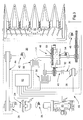
- FIG. 2 shows the transmission 30 with a maize header 32
- FIG. 7 shows the same Transmission 30 with a cutting unit 34.
- the transmission 30 includes a second motor 36 having a second output shaft 38, a second input shaft 40 connected to the second output shaft 38 is connected, a first input shaft 42, via a Belt drive 44 with fixed gear ratio with the electrically operable coupling 24 is connected, and a Harvest header output shaft 46, which with the header 14th connected is.
- a planetary gear 48 connects the first Input shaft 42, the second input shaft 40 and the Harvest header output shaft 46 with each other.
- the planetary gear 48 includes a connected to the first input shaft 42 Sun gear 50 and a ring gear 52, with the second Input shaft 40 is connected.
- the planetary gear 48 includes Furthermore, a Planetenradzusammenbau 54, the planetary gears both with the sun gear 50 and with the ring gear 52 in Engage, and with the header output shaft 46th connected is.
- the transmission 30 further comprises a in Normal operation (and at rest) disengaged first brake 56, which is coupled to the first input shaft 42, and one in Normal operation (and at rest) closed second brake 58, which is coupled to the second input shaft 40.
- the second Motor 36 is in the illustrated embodiment hydrostatic engine, but there may be other engine types used as electric motors with adjustable Speed.
- the operation of the transmission 30 is controlled by a control circuit 60, which is suitable to be instructed by the operator received, the desired operating mode of the header 14th correspond.
- the control circuit 60 is arranged with the electrically operable coupling 24, the second motor 36, the first brake 56 and the second brake 58 to communicate.
- the Control circuit 60 is arranged to be electrically operable To instruct clutch 24, the first output shaft 26 with the first To connect input shaft 42 and the second motor 36th to instruct variable rotational speeds of the second To assume output shaft 38 in the forward and reverse directions and uphold.
- the control circuit 60 is still adapted to cause the first brake 56, the rotation of to stop the first input shaft 42, and the second brake 58 to cause the second input shaft 40 to rotate freely give.
- the control circuit 60 may be in a number of Configurations may be arranged for powered machines are typical, but here is as an electronic controller 62nd shown.
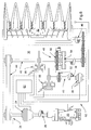
- Figures 3 and 8 show the transmission 30 during normal Operation of the header 14 at fixed speed.
- the Figure 3 shows the transmission 30 with a corn picker 32 and the Figure 8 shows the gear 30 with a cutting unit 34.
- Als Response to an operator's instruction for this mode the controller 62 causes the electrically operable clutch 24, whereby the first output shaft 26 via the Belt drive 44 is connected to the first input shaft 42.
- the first brake 56 remains in normal operation out of engagement and allows the first input shaft 42 to rotate.
- the second Brake 58 remains in normal operation engaged and prevents the second input shaft 40 and the ring gear 52 of the planetary gear 48 at turning.
- FIG. 4 shows the transmission 30 with a corn picker 32 and FIG. 9 shows the transmission 30 with a cutting mechanism 34
- the controller 62 causes the electrically operable clutch 24, or he continues, making the first Output shaft 26 via the belt drive 44 with the first Input shaft 42 is connected.
- the first brake 56 remains in normal operation disengaged and allowed the first Turn input shaft 42.
- the controller 62 causes the second brake 58 to disengage, which is the second Input shaft 40 and the ring gear 52 of the planetary gear 48th allows to rotate.
- the controller 62 is set up, continue to instruct the second motor 36, the second Output shaft 38 either to rotate forward or backward, depending on an instruction of the operator for higher or lower rate of header 14 in proportion to the normal operation with fixed speed.
- the controller 62 will be in the absence operator's instructions, the second motor 36 instruct, in this mode, the second output shaft 38th to keep stationary. While the second output shaft 40 and the Ring wheel 52 are held stationary, the rotation of the first Input shaft 42 and the sun gear 50 thus on the Planetary gear assembly 54 and the header output shaft 46th proportionally translated. The resulting rotation of the Header output shaft 46 is therefore normal Operation of the header 14 at a fixed speed.
- the controller 62 causes the second motor 36, the second output shaft 38 with an operator input forward proportional speed.
- the rotation the second input shaft 40 and the ring gear 52 is therefore the Planetary gear assembly 54 and the header output shaft 46th proportionally added.
- the resulting rotational speed the header output shaft 46 is therefore larger than the normal operation of the header 14 with fixed Speed.
- the rotation of the second input shaft 40 and the ring gear 52 of the Planetenradzusammenbau 54 and the Harvest header output shaft 46 proportionally subtracted, and the resulting rotational speed of the header output shaft 46 is smaller than the fixed one during normal operation Speed.
- the Operating speed of the driven by the gear 30 Header 14 can be controlled automatically, for example in Reaction to a changed propulsion speed and / or changing crop characteristics.
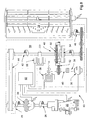
- Figures 5 and 10 show the transmission 30 during a rapid stopping of the header 14.
- the figure 5 shows the Transmission 30 with a corn picker 32 and the figure 10 shows the Transmission 30 with a cutting unit 34.
- a closing of the electrically actuated clutch 24th instruct so that it is the electrically actuated clutch is allowed to go back to their separate rest position, where the first output shaft 26 from the belt drive 44 and the first Input shaft 42 is disconnected.
- the second brake 58 remains in their normal resting position, or goes back to what the second input shaft 40 and the ring gear 52 of the planetary gear 48 prevents turning.
- the controller 62 causes the first one Brake 56 intervene, however, causing the first input shaft 42 and the sun gear 50 of the planetary gear 48 stops quickly. Because the Rotation of both the ring gear 52 and the sun gear 50 of the Planetary gears 48 are brought to a quick stop, is also the rotation of the engaged with it Planetenradzusammenbaus 54 and the header output shaft 46th brought to a halt, causing a quick shutdown of the mechanically driven functions of the header 14 to Episode has.
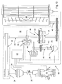
- Figures 6 and 11 show the transmission 30 during operation of the header 14 with lower, changeable Speed.
- 6 shows the transmission 30 with a Corn picker 32 and the figure 11 shows the transmission 30 with a Cutter 34.
- the controller 62 In response to an operator's instruction for this Mode hears the controller 62 with the instruction to the electrically operated clutch 24 to close on, so that it the electrically actuated clutch 24 is allowed in their separate resting position to go back or stay there, wherein the first output shaft 26 from the belt drive 44 and the first input shaft 42 is disconnected.
- the controller 62 causes the first brake 56 to engage or he continues with what the first input shaft 42 and the Sun gear 50 of the planetary gear 48 prevents rotation.
- Controller 62 disengages second brake 58 go what it is the second input shaft 40 and the ring gear 52 of the Planetary gear 48 allows to turn.
- Controller 62 configured to instruct the second motor 36, the second output shaft 38 either forward or backward turn, depending on an operator's instruction for one slow forward or reverse operation of the header 14.
- the controller 62 the second motor 36, the second Output shaft 38 with a proportional to the operator input Speed to turn forward.
- For stationary held first input shaft 42 and stationary sun gear 50 is the Rotation of the second input shaft 40 and the ring gear 52nd proportional to the Planetenradzusammenbau 54 and the Header output shaft 46 translated.
- the resulting Rotational speed of the header output shaft 46 corresponds a desired forward operation of the header 14 with low speed. If the operator vice versa one reversing operation of the header 14 with a requested, low speed, the Controller 62 to the second motor 36, the second output shaft 38 with a speed proportional to the operator input to turn backwards.
Landscapes
- Life Sciences & Earth Sciences (AREA)
- Environmental Sciences (AREA)
- Engineering & Computer Science (AREA)
- Mechanical Engineering (AREA)
- Harvester Elements (AREA)
- Structure Of Transmissions (AREA)
Abstract
Description
- Fig. 1
- eine seitliche Ansicht eines landwirtschaftlichen Mähdreschers mit einem Maispflücker,
- Fig. 2
- eine schematische Ansicht eines stufenlos verstellbaren Getriebes während des Antreibens eines Maispflückers, dargestellt in ausgerückter Stellung,
- Fig. 3
- eine schematische Ansicht des stufenlos verstellbaren Getriebes während des Antreibens eines Maispflückers, dargestellt in normalem Betrieb mit fester Geschwindigkeit,
- Fig. 4
- eine schematische Ansicht des stufenlos verstellbaren Getriebes während des Antreibens eines Maispflückers, dargestellt im Betrieb mit verstellbarer, hoher Geschwindigkeit,
- Fig. 5
- eine schematische Ansicht des stufenlos verstellbaren Getriebes während des Antreibens eines Maispflückers, dargestellt beim schnellen Anhalten des Maispflückers,
- Fig. 6
- eine schematische Ansicht des stufenlos verstellbaren Getriebes während des Antreibens eines Maispflückers, dargestellt im Betrieb mit verstellbarer, langsamer Geschwindigkeit,
- Fig. 7
- eine schematische Ansicht des stufenlos verstellbaren Getriebes während des Antreibens eines Schneidwerks, dargestellt in ausgerückter Stellung,
- Fig. 8
- eine schematische Ansicht des stufenlos verstellbaren Getriebes während des Antreibens eines Schneidwerks, dargestellt in normalem Betrieb mit fester Geschwindigkeit,
- Fig. 9
- eine schematische Ansicht des stufenlos verstellbaren Getriebes während des Antreibens eines Schneidwerks, dargestellt im Betrieb mit verstellbarer, hoher Geschwindigkeit,
- Fig. 10
- eine schematische Ansicht des stufenlos verstellbaren Getriebes während des Antreibens eines Schneidwerks, dargestellt beim schnellen Anhalten des Maispflückers,
- Fig. 11
- eine schematische Ansicht des stufenlos verstellbaren Getriebes während des Antreibens eines Maispflückers, dargestellt im Betrieb mit verstellbarer, langsamer Geschwindigkeit.
Claims (11)
- Antriebsanordnung zum Antrieb eines Erntevorsatzes (14) einer Erntemaschine, mit:wobei die erste Eingangswelle (42) mit einem der Elemente des Planetengetriebes (48) verbunden ist, die zweite Eingangswelle (40) mit einem anderen der Elemente des Planetengetriebes (48) verbunden ist, und die Erntevorsatzausgangswelle (46) mit dem verbleibenden Element des Planetengetriebes (48) verbunden ist, dadurch gekennzeichnet, dass die zweite Eingangswelle (40) mit einer zweiten Bremse (58) verbunden ist, mit der die zweite Eingangswelle (40) wahlweise anhaltbar ist.einem ersten Motor (20) mit einer in Drehung versetzbaren ersten Ausgangswelle (26), die mit einer drehbaren ersten Eingangswelle (42) verbindbar ist,einem zweiten, mit veränderbarer Geschwindigkeit vorwärts und rückwärts antreibbaren Motor (36), der mit einer zweiten Ausgangswelle (38) versehen ist, die mit einer zweiten Eingangswelle (40) verbunden ist,einer Erntevorsatzausgangswelle (46) zum Antrieb eines Erntevorsatzes (14) undeinem Planetengetriebe (48), das als Elemente ein Sonnenrad (50), ein Ringrad (52) und einen Planetenradzusammenbau (54) umfasst, der Planetenräder aufweist, die mit dem Sonnenrad (50) und dem Ringrad (52) im Eingriff stehen,
- Antriebsanordnung nach Anspruch 1, dadurch gekennzeichnet, dass eine schaltbare Kupplung (24) zwischen der ersten Ausgangswelle (26) und der ersten Eingangswelle (42) angeordnet ist.
- Antriebsanordnung nach Anspruch 2, dadurch gekennzeichnet, dass eine erste Bremse (56) mit der ersten Eingangswelle (42) verbunden ist, mit der die erste Eingangswelle (42) wahlweise anhaltbar ist.
- Antriebsanordnung nach einem der vorhergehenden Ansprüche, dadurch gekennzeichnet, dass ein Steuerschaltkreis (60) vorhanden ist, der eingerichtet ist, Anweisungen von einem Bediener zu empfangen und mit der zweiten Bremse (58) und dem zweiten Motor (36) und vorzugsweise mit der Kupplung (24) und/oder der ersten Bremse (56) in Wirkverbindung steht.
- Antriebsanordnung nach Anspruch 4, dadurch gekennzeichnet, dass der Steuerschaltkreis (60) betreibbar ist, die Kupplung (24) zu veranlassen, die erste Ausgangswelle (26) mit der ersten Eingangswelle (42) zu verbinden und den zweiten Motor (36) zu veranlassen, sich mit einer veränderbaren Vorwärts- oder Rückwärtsgeschwindigkeit der zweiten Ausgangswelle (38) zu drehen.
- Antriebsanordnung nach Anspruch 4 oder 5, dadurch gekennzeichnet, dass der Steuerschaltkreis (60) betreibbar ist, die Kupplung (24) zu veranlassen, die erste Ausgangswelle (26) von der ersten Eingangswelle (42) zu trennen und die erste Bremse (56) zu aktivieren und den zweiten Motor (36) zu veranlassen, sich mit einer veränderbaren Vorwärts- oder Rückwärtsgeschwindigkeit der zweiten Ausgangswelle (38) zu drehen.
- Antriebsanordnung nach einem der Ansprüche 4 bis 6, dadurch gekennzeichnet, dass der Steuerschaltkreis (60) betreibbar ist, die Kupplung (24) zu veranlassen, die erste Ausgangswelle (26) von der ersten Eingangswelle (42) zu trennen und die erste Bremse (56) und die zweite Bremse (58) zu aktivieren und den zweiten Motor (36) anzuhalten.
- Antriebsanordnung nach einem der Ansprüche 4 bis 7, dadurch gekennzeichnet, dass der Steuerschaltkreis (60) betreibbar ist, die Kupplung (24) zu veranlassen, die erste Ausgangswelle (26) mit der ersten Eingangswelle (42) zu verbinden und die zweite Bremse (58) zu aktivieren und den zweiten Motor (36) anzuhalten.
- Antriebsanordnung nach Anspruch 8, dadurch gekennzeichnet, dass die Antriebsgeschwindigkeit der Erntevorsatzantriebswelle (46) bei geschlossener Kupplung (24) und aktivierter zweiter Bremse (58) einer normalen Betriebsgeschwindigkeit entspricht.
- Antriebsanordnung nach einem der vorhergehenden Ansprüche, dadurch gekennzeichnet, dass die erste Eingangswelle (42) mit dem Sonnenrad (50) verbunden ist, die zweite Eingangswelle (40) mit dem Ringrad (52) verbunden ist, und die Erntevorsatzausgangswelle (46) mit dem einen Planetenradzusammenbau (54) verbunden ist.
- Erntemaschine, insbesondere Mähdrescher, mit einer Antriebsanordnung nach einem der vorhergehenden Ansprüche.
Applications Claiming Priority (2)
| Application Number | Priority Date | Filing Date | Title |
|---|---|---|---|
| US10/791,328 US7213389B2 (en) | 2004-03-02 | 2004-03-02 | Infinitely variable transmission for a combine header unit |
| US791328 | 2004-03-02 |
Publications (2)
| Publication Number | Publication Date |
|---|---|
| EP1570724A1 true EP1570724A1 (de) | 2005-09-07 |
| EP1570724B1 EP1570724B1 (de) | 2007-09-26 |
Family
ID=34750586
Family Applications (1)
| Application Number | Title | Priority Date | Filing Date |
|---|---|---|---|
| EP05101397A Expired - Lifetime EP1570724B1 (de) | 2004-03-02 | 2005-02-24 | Antriebsanordnung zum Antrieb eines Erntevorsatzes einer Erntemaschine |
Country Status (3)
| Country | Link |
|---|---|
| US (1) | US7213389B2 (de) |
| EP (1) | EP1570724B1 (de) |
| DE (1) | DE502005001549D1 (de) |
Cited By (2)
| Publication number | Priority date | Publication date | Assignee | Title |
|---|---|---|---|---|
| EP2281434A3 (de) * | 2009-07-30 | 2011-05-04 | CLAAS Saulgau GmbH | Vorsatzgerät mit Querfördereinrichtung und Drehzahlanpassung |
| EP3000306A1 (de) * | 2014-09-26 | 2016-03-30 | CLAAS Selbstfahrende Erntemaschinen GmbH | Selbstfahrende erntemaschine |
Families Citing this family (12)
| Publication number | Priority date | Publication date | Assignee | Title |
|---|---|---|---|---|
| US7849952B2 (en) * | 2006-08-24 | 2010-12-14 | Macdon Industries Ltd | Tractor with two engine settings |
| DE102007053436A1 (de) * | 2007-11-07 | 2009-05-14 | Claas Selbstfahrende Erntemaschinen Gmbh | Motorregelung einer selbstfahrenden Arbeitsmaschine |
| US7748202B2 (en) * | 2007-11-29 | 2010-07-06 | Deere & Company | Agricultural harvester speed control |
| BE1018875A3 (nl) * | 2009-09-01 | 2011-10-04 | Cnh Belgium Nv | Landbouwmachine met variabele toerentalregeling. |
| US9560806B2 (en) | 2012-06-28 | 2017-02-07 | Forage Innovations B.V. | Control of conveyor speed in a bale gathering apparatus |
| ITMI20131128A1 (it) * | 2013-07-04 | 2015-01-05 | Laverda S P A | Gruppo ruote dentate |
| US10349580B2 (en) * | 2017-07-06 | 2019-07-16 | Mac Don Industries Ltd. | Draper header for attachment to a harvesting machine |
| US11051453B2 (en) * | 2018-11-14 | 2021-07-06 | Cnh Industrial America Llc | Reel drive assembly for an agricultural header |
| US11606901B2 (en) * | 2019-05-31 | 2023-03-21 | Cnh Industrial America Llc | Speed control method and system for harvester |
| JP7134140B2 (ja) * | 2019-06-25 | 2022-09-09 | 株式会社クボタ | 収穫機 |
| US20210274710A1 (en) * | 2020-03-05 | 2021-09-09 | Cnh Industrial America Llc | Variable speed reel drive for a header of an agricultural harvester |
| DE102024111814A1 (de) * | 2024-04-26 | 2025-10-30 | Maschinenfabrik Bernard Krone GmbH & Co. KG | Vorsatzgerät |
Citations (2)
| Publication number | Priority date | Publication date | Assignee | Title |
|---|---|---|---|---|
| US6247296B1 (en) * | 1999-04-23 | 2001-06-19 | Deere & Comapny | Drive arrangement for the crop conveying and/or processing mechanism of a harvesting machine |
| US20030109292A1 (en) * | 2001-12-12 | 2003-06-12 | Schroeder Jay D. | Hydro-mechanical variable speed feeder/header drive for an agricultural combine |
Family Cites Families (9)
| Publication number | Priority date | Publication date | Assignee | Title |
|---|---|---|---|---|
| US4019404A (en) | 1975-03-21 | 1977-04-26 | Sundstrand Corporation | Power transmission |
| US4663713A (en) | 1984-02-21 | 1987-05-05 | J. I. Case Company | Automatic power control for variable power train |
| US5667452A (en) | 1995-04-06 | 1997-09-16 | Caterpillar Inc. | Split torque transmission |
| US5865700A (en) | 1997-05-01 | 1999-02-02 | Case Corporation | Hydro-mechanical transmission |
| US6247295B1 (en) | 1999-10-28 | 2001-06-19 | New Holland North America, Inc. | Hydro-mechanical transmission system for an agricultural combine |
| US6587771B2 (en) | 2001-11-15 | 2003-07-01 | Case Corporation | Variable feeder and header drive system for an agricultural harvesting machine |
| US6663525B1 (en) * | 2002-07-17 | 2003-12-16 | Case Corporation | Hydro-mechanical transmission with automatic braking capability and method of operation |
| US6984171B2 (en) * | 2002-07-19 | 2006-01-10 | Cnh America Llc | Hydro-mechanical threshing rotor control system for an agricultural combine |
| DE10245885A1 (de) * | 2002-09-30 | 2004-04-08 | Deere & Company, Moline | Erntemaschine |
-
2004
- 2004-03-02 US US10/791,328 patent/US7213389B2/en not_active Expired - Lifetime
-
2005
- 2005-02-24 EP EP05101397A patent/EP1570724B1/de not_active Expired - Lifetime
- 2005-02-24 DE DE502005001549T patent/DE502005001549D1/de not_active Expired - Lifetime
Patent Citations (2)
| Publication number | Priority date | Publication date | Assignee | Title |
|---|---|---|---|---|
| US6247296B1 (en) * | 1999-04-23 | 2001-06-19 | Deere & Comapny | Drive arrangement for the crop conveying and/or processing mechanism of a harvesting machine |
| US20030109292A1 (en) * | 2001-12-12 | 2003-06-12 | Schroeder Jay D. | Hydro-mechanical variable speed feeder/header drive for an agricultural combine |
Cited By (2)
| Publication number | Priority date | Publication date | Assignee | Title |
|---|---|---|---|---|
| EP2281434A3 (de) * | 2009-07-30 | 2011-05-04 | CLAAS Saulgau GmbH | Vorsatzgerät mit Querfördereinrichtung und Drehzahlanpassung |
| EP3000306A1 (de) * | 2014-09-26 | 2016-03-30 | CLAAS Selbstfahrende Erntemaschinen GmbH | Selbstfahrende erntemaschine |
Also Published As
| Publication number | Publication date |
|---|---|
| US7213389B2 (en) | 2007-05-08 |
| EP1570724B1 (de) | 2007-09-26 |
| DE502005001549D1 (de) | 2007-11-08 |
| US20050193698A1 (en) | 2005-09-08 |
Similar Documents
| Publication | Publication Date | Title |
|---|---|---|
| EP1609351B1 (de) | Erntevorsatzantrieb | |
| EP2345320B1 (de) | Selbstfahrende Erntemaschine | |
| DE69532870T2 (de) | Kraftantriebsreihe für landwirtschaftliche Erntemaschinen | |
| EP1046334B1 (de) | Antriebseinrichtung der Förder- und/oder Gutbearbeitungsvorrichtung einer Erntemaschine | |
| DE19812500B4 (de) | Zuführvorrichtung | |
| EP0702513B2 (de) | Landwirtschaftliche maschine, insbesondere selbstfahrende grossballenpresse | |
| EP2404496B1 (de) | Maispflücker | |
| EP1570724B1 (de) | Antriebsanordnung zum Antrieb eines Erntevorsatzes einer Erntemaschine | |
| EP3906770B1 (de) | Antriebssystem für eine selbstfahrende erntemaschine | |
| EP2687079A2 (de) | Reihenunabhängig arbeitendes Vorsatzgerät zum Ernten von stängeligem Erntegut | |
| BE1021620B1 (de) | Antriebssystem für eine erntemaschine | |
| EP3326446B1 (de) | Geschwindigkeitskontrolle einer erntemaschine | |
| EP2329981B1 (de) | Antriebsanordnung und Verfahren für eine Arbeitsmaschine mit zwei Verbrennungsmotoren | |
| DE102021114960A1 (de) | Erntevorsatz zur Ernte stängelartiger Pflanzen mit drehzahlveränderlich angetriebenem Mulchgerät | |
| DE102009028094B4 (de) | Selbstfahrende Erntemaschine | |
| BE1028458B1 (de) | Antriebssystem für eine Erntemaschine | |
| DE10260480A1 (de) | Antriebssystem einer selbstfahrenden Arbeitsmaschine | |
| DE202011002195U1 (de) | Selbstfahrende landwirtschaftliche Erntemaschine mit einem elektromotorisch angetriebenen Arbeitsorgan | |
| DE102009028056A1 (de) | Selbstfahrende Erntemaschine | |
| EP1741331B1 (de) | Feldhäcksler und Verfahren zum Betrieb | |
| EP1566090B1 (de) | Maschine zum Mähen von stängelartigem Erntegut | |
| EP4371393B1 (de) | Selbstfahrende erntemaschine | |
| DE102024111814A1 (de) | Vorsatzgerät | |
| EP2702860B1 (de) | Selbstfahrende landwirtschaftliche Erntemaschine | |
| EP4371391A1 (de) | Selbstfahrende erntemaschine |
Legal Events
| Date | Code | Title | Description |
|---|---|---|---|
| PUAI | Public reference made under article 153(3) epc to a published international application that has entered the european phase |
Free format text: ORIGINAL CODE: 0009012 |
|
| AK | Designated contracting states |
Kind code of ref document: A1 Designated state(s): AT BE BG CH CY CZ DE DK EE ES FI FR GB GR HU IE IS IT LI LT LU MC NL PL PT RO SE SI SK TR |
|
| AX | Request for extension of the european patent |
Extension state: AL BA HR LV MK YU |
|
| 17P | Request for examination filed |
Effective date: 20060307 |
|
| AKX | Designation fees paid |
Designated state(s): BE DE IT |
|
| GRAP | Despatch of communication of intention to grant a patent |
Free format text: ORIGINAL CODE: EPIDOSNIGR1 |
|
| GRAS | Grant fee paid |
Free format text: ORIGINAL CODE: EPIDOSNIGR3 |
|
| GRAA | (expected) grant |
Free format text: ORIGINAL CODE: 0009210 |
|
| AK | Designated contracting states |
Kind code of ref document: B1 Designated state(s): BE DE IT |
|
| REF | Corresponds to: |
Ref document number: 502005001549 Country of ref document: DE Date of ref document: 20071108 Kind code of ref document: P |
|
| PLBE | No opposition filed within time limit |
Free format text: ORIGINAL CODE: 0009261 |
|
| STAA | Information on the status of an ep patent application or granted ep patent |
Free format text: STATUS: NO OPPOSITION FILED WITHIN TIME LIMIT |
|
| 26N | No opposition filed |
Effective date: 20080627 |
|
| PGFP | Annual fee paid to national office [announced via postgrant information from national office to epo] |
Ref country code: IT Payment date: 20140224 Year of fee payment: 10 |
|
| PG25 | Lapsed in a contracting state [announced via postgrant information from national office to epo] |
Ref country code: IT Free format text: LAPSE BECAUSE OF NON-PAYMENT OF DUE FEES Effective date: 20150224 |
|
| PGFP | Annual fee paid to national office [announced via postgrant information from national office to epo] |
Ref country code: BE Payment date: 20190227 Year of fee payment: 15 |
|
| REG | Reference to a national code |
Ref country code: BE Ref legal event code: MM Effective date: 20200229 |
|
| PG25 | Lapsed in a contracting state [announced via postgrant information from national office to epo] |
Ref country code: BE Free format text: LAPSE BECAUSE OF NON-PAYMENT OF DUE FEES Effective date: 20200229 |
|
| PGFP | Annual fee paid to national office [announced via postgrant information from national office to epo] |
Ref country code: DE Payment date: 20230119 Year of fee payment: 19 |
|
| REG | Reference to a national code |
Ref country code: DE Ref legal event code: R119 Ref document number: 502005001549 Country of ref document: DE |
|
| PG25 | Lapsed in a contracting state [announced via postgrant information from national office to epo] |
Ref country code: DE Free format text: LAPSE BECAUSE OF NON-PAYMENT OF DUE FEES Effective date: 20240903 |
|
| PG25 | Lapsed in a contracting state [announced via postgrant information from national office to epo] |
Ref country code: DE Free format text: LAPSE BECAUSE OF NON-PAYMENT OF DUE FEES Effective date: 20240903 |