EP1570720A2 - Trimming apparatus - Google Patents
Trimming apparatus Download PDFInfo
- Publication number
- EP1570720A2 EP1570720A2 EP05251232A EP05251232A EP1570720A2 EP 1570720 A2 EP1570720 A2 EP 1570720A2 EP 05251232 A EP05251232 A EP 05251232A EP 05251232 A EP05251232 A EP 05251232A EP 1570720 A2 EP1570720 A2 EP 1570720A2
- Authority
- EP
- European Patent Office
- Prior art keywords
- handle
- trimming apparatus
- cutting head
- rotatable
- user
- Prior art date
- Legal status (The legal status is an assumption and is not a legal conclusion. Google has not performed a legal analysis and makes no representation as to the accuracy of the status listed.)
- Withdrawn
Links
Images


Classifications
-
- A—HUMAN NECESSITIES
- A01—AGRICULTURE; FORESTRY; ANIMAL HUSBANDRY; HUNTING; TRAPPING; FISHING
- A01D—HARVESTING; MOWING
- A01D69/00—Driving mechanisms or parts thereof for harvesters or mowers
- A01D69/02—Driving mechanisms or parts thereof for harvesters or mowers electric
-
- A—HUMAN NECESSITIES
- A01—AGRICULTURE; FORESTRY; ANIMAL HUSBANDRY; HUNTING; TRAPPING; FISHING
- A01D—HARVESTING; MOWING
- A01D34/00—Mowers; Mowing apparatus of harvesters
- A01D34/01—Mowers; Mowing apparatus of harvesters characterised by features relating to the type of cutting apparatus
- A01D34/412—Mowers; Mowing apparatus of harvesters characterised by features relating to the type of cutting apparatus having rotating cutters
- A01D34/416—Flexible line cutters
-
- A—HUMAN NECESSITIES
- A01—AGRICULTURE; FORESTRY; ANIMAL HUSBANDRY; HUNTING; TRAPPING; FISHING
- A01D—HARVESTING; MOWING
- A01D34/00—Mowers; Mowing apparatus of harvesters
- A01D34/01—Mowers; Mowing apparatus of harvesters characterised by features relating to the type of cutting apparatus
- A01D34/412—Mowers; Mowing apparatus of harvesters characterised by features relating to the type of cutting apparatus having rotating cutters
- A01D34/63—Mowers; Mowing apparatus of harvesters characterised by features relating to the type of cutting apparatus having rotating cutters having cutters rotating about a vertical axis
- A01D34/76—Driving mechanisms for the cutters
- A01D34/78—Driving mechanisms for the cutters electric
-
- A—HUMAN NECESSITIES
- A01—AGRICULTURE; FORESTRY; ANIMAL HUSBANDRY; HUNTING; TRAPPING; FISHING
- A01D—HARVESTING; MOWING
- A01D34/00—Mowers; Mowing apparatus of harvesters
- A01D34/01—Mowers; Mowing apparatus of harvesters characterised by features relating to the type of cutting apparatus
- A01D34/412—Mowers; Mowing apparatus of harvesters characterised by features relating to the type of cutting apparatus having rotating cutters
- A01D34/63—Mowers; Mowing apparatus of harvesters characterised by features relating to the type of cutting apparatus having rotating cutters having cutters rotating about a vertical axis
- A01D34/82—Other details
- A01D34/824—Handle arrangements
-
- A—HUMAN NECESSITIES
- A01—AGRICULTURE; FORESTRY; ANIMAL HUSBANDRY; HUNTING; TRAPPING; FISHING
- A01D—HARVESTING; MOWING
- A01D34/00—Mowers; Mowing apparatus of harvesters
- A01D34/01—Mowers; Mowing apparatus of harvesters characterised by features relating to the type of cutting apparatus
- A01D34/412—Mowers; Mowing apparatus of harvesters characterised by features relating to the type of cutting apparatus having rotating cutters
- A01D34/63—Mowers; Mowing apparatus of harvesters characterised by features relating to the type of cutting apparatus having rotating cutters having cutters rotating about a vertical axis
- A01D34/82—Other details
- A01D34/828—Safety devices
-
- A—HUMAN NECESSITIES
- A01—AGRICULTURE; FORESTRY; ANIMAL HUSBANDRY; HUNTING; TRAPPING; FISHING
- A01D—HARVESTING; MOWING
- A01D34/00—Mowers; Mowing apparatus of harvesters
- A01D34/835—Mowers; Mowing apparatus of harvesters specially adapted for particular purposes
- A01D34/90—Mowers; Mowing apparatus of harvesters specially adapted for particular purposes for carrying by the operator
- A01D34/902—Ergonomic provisions
-
- A—HUMAN NECESSITIES
- A01—AGRICULTURE; FORESTRY; ANIMAL HUSBANDRY; HUNTING; TRAPPING; FISHING
- A01G—HORTICULTURE; CULTIVATION OF VEGETABLES, FLOWERS, RICE, FRUIT, VINES, HOPS OR SEAWEED; FORESTRY; WATERING
- A01G3/00—Cutting implements specially adapted for horticultural purposes; Delimbing standing trees
- A01G3/06—Hand-held edge trimmers or shears for lawns
Definitions
- This invention relates to trimming apparatus, for example for use in gardens.
- One form of a current garden trimmer is substantially a cutting head on an elongate body which is held by the user by means of a handle provided at the opposite end of the elongate body to the cutting head.
- the elongate body of current garden trimmers enables a user to trim surfaces such as lawns and lawn edges whilst standing up.
- surfaces such as lawns and lawn edges whilst standing up.
- the use of a trimmer is required whilst the user is closer to the surface to be trimmed, for example whilst crouching in the garden carrying out other garden maintenance activities such as weeding, or where the trimming of a surface requires the user to be relatively close to the surface for accuracy, for example trimming a shrub or hedge.
- trimmers are powered by means of mains power supplied via a power lead.
- power leads can often become entangled with themselves and items generally found in gardens, for example ornaments and garden furniture.
- Accidental damage to a power lead by the cutting head of a trimmer can also occur.
- a trimming apparatus comprising a handle means and a cutting head, the cutting head being attached directly to the handle means and comprising a motor and a rotatable cutting edge, wherein shielding means adapted to protect a hand of a user is provided on the handle means.
- the handle means may contain at least one battery.
- the at least one battery may be removable.
- the at least one battery may be rechargeable, for example whilst in the trimming apparatus or by recharging means separate to the trimming apparatus.
- the rotatable cutting edge may be a blade or a cutting wire, for example selected from plastics and metal material.
- the rotatable cutting edge may be removable from the cutting head, for example for sharpening or replacement.
- the rotatable cutting edge may be rotatable by the motor to produce a cutting action.
- Rotating means may be provided between the handle means and the cutting head.
- the rotating means may allow the cutting head to rotate about an axis thereof relative to the handle means such that the orientation of the plane of the rotatable cutting edge relative to the handle can be changed.
- the cutting head may be rotatable through an angle of 180 degrees and may be rotatable in either direction about the axis of the rotating means relative to the handle means.
- Stop means may be provided to prevent the cutting head being rotated through more than 360 degrees about the axis of the rotating means relative to the handle means.
- the shielding means may be arranged to support a wrist of a user of the apparatus and substantially protect a hand of the user from sharp objects.
- the shielding means may be arranged to extend from the handle to both sides of the wrist of the user.
- the shielding means may be of convex form.
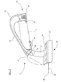
- the trimming apparatus 2 shown in Figure 1 comprises a handle 4, suitably moulded of plastics material and of generally circular cross-section.
- a cutting head 8 is rotatably attached to a first end 6 of the handle 4 furthest from the user in use.
- the handle 4 of the trimming apparatus 2 contains an elongate tubular compartment 10 running substantially the entire length of the handle 4 and in which an elongate battery pack 12 is provided.
- the battery pack 12 is removable from the handle 4 and is rechargeable by means (not shown) separate to the trimming apparatus 2.
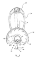
- the removable battery pack 12 (as shown in Figure 3) is provided with battery terminals 14 in a region 16 of a first end of the battery pack 12 which are positioned to complement the position of electrical contacts (not shown) provided within the tubular compartment 10 of the handle 4.
- the battery pack 12 is held in place within the handle 4 by means of a releaseable catch mechanism 20.
- a release means 22 Provided on either side of the second end of the battery pack 12 is a release means 22 which releases the catch mechanism 20 to enable the battery pack 12 to be removed.
- a button 24 is provided on the handle 4.
- the button 24 activates a micro switch 26 provided within the handle 4 such that electrical contact can be made between the battery pack and a motor 28, described hereinafter, whereby the motor 28 can be energised.
- the micro switch 26 ensures that the motor 28 is only energised whilst the button 24 is depressed. For safety purposes, if the button 24 is released the micro switch 26 causes the motor 28 to be de-energised.
- a convex shielding member 34 rigidly attached to a front portion 30 and a rear portion 32 of opposite sides of the handle 4 is a convex shielding member 34.
- the shielding members are arranged to provide support for a wrist of the user and to protect a hand of the user from sharp objects, such as cut ends of a trimmed item or thistles, and stinging garden plants, for example nettles.
- the shielding members 34 extend in the longitudinal direction of the handle 4 and are dimensioned such that a portion 36 of each shielding member 34 is spaced further from the handle 4 at a region near to the rear portion 32 of the handle 4 than at a region near to the front portion 30.
- the shielding members 34 when the trimming apparatus is orientated as shown in Figure 1, extend from the handle 4 in substantially upwardly and outwardly directions relative to the handle 4 such that a cross section of the shielding members 34 and handle 4 shows a "V" shaped section, as shown in Figure 4.
- the "V” shaped section enables the wrist of the user to be supported on both sides.
- the "V” shaped section has an included angle in a range substantially from 15 degrees to 150 degrees.
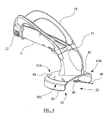
- the cutting head 8 is formed with an internal compartment 38 (as shown in Figure 2), in which is provided the motor 28, and an external rotating body 40 (as shown in Figures 4 and 5) connected to the motor and rotatable therewith.
- the external rotating body 40 is situated in the region of an end 42 of the cutting head 8 furthest from the handle 4.
- a protrusion 44 is provided in an edge region of an end face 45 of the rotating body 40 furthest from the handle 4. The protrusion extends away from the end face 45.
- a rotatable blade 46 of plastics material having a cutting edge 39 is removably attached to the protrusion 44 in a recess (not shown) provided in the surface of, and around the circumference of, the protrusion.
- the blade 46 is provided with an aperture 47 in the shape of a figure "8", that is two co-joined circular aperture portions.
- a first portion 47A of the aperture, nearest to a tip 41 of the blade, is larger than a second portion 47B of the aperture, the second portion 47B having a diameter substantially complementary to that of the recess in the surface of the protrusion 44.
- the first portion 47A is dimensioned to be larger than the diameter of the protrusion 44 in order that the blade 46 can be placed over the protrusion. Moving the tip 41 of the blade 46 perpendicular to the longitudinal axis of the protrusion 44 and away from the protrusion 44 causes the second portion 47B of the aperture 47 to be pulled onto the protrusion 44 and secures the blade in the recess in the surface of the protrusion.
- a pair of retaining members 49 are provided a distance from the protrusion 44 such that a portion 51 of the blade 46 is positioned between the protrusion 44 and the retaining members 49 when attached to the trimming apparatus.
- the retaining members 49 prevent the blade 46 from rotating relative to the protrusion 44, for example when the blade 46 comes into contact with a surface to be trimmed, as shoulder regions 55 of the blade 46 are substantially prevented from rotating past the retaining members 49 by means of contact between the shoulder portions 55 and the retaining members 49.
- the motor 28 is powered by the battery pack 12 provided in the handle 4.
- the motor 28 is rotatably connected to the external rotating body 40 and causes the cutting edge 39 of the blade 46 to rotate in a circular path about an axis substantially perpendicular to the longitudinal axis of the cutting head 8.
- the positioning of the protrusion 44 at the edge region of the end face 45 of the rotating body 40 ensures that the radius of the circular path followed by the tip 41 of the blade 46 is greater than that of the tip 41 of the blade 46 rotated about the length of the blade.
- a guard means 48 in the form of a partial dish-like structure.
- the guard means 48 extends laterally outwards from the end 42 of the cutting head 8 in the region 43A of the cutting head nearest to the handle 4 and to the side regions 43B, 43C of the region 43A nearest to the handle (as shown in Figure 4) to form a barrier between a hand of the user holding the handle and the rotating body 40.
- a partially cylindrical wall portion 50 of the guard means 48 extends away from the handle 4 such that the rotating body 40 is enclosed circumferentially by the guard means 48.
- the guard means 48 is of a sufficient diameter that the blade 46 is not obstructed from being rotated.
- the guard means 48 is not provided in the region 52 of the cutting head 8 to enable the blade 46 attached to the rotating body 40 to extend outwards from the trimming apparatus 2 in order that the blade 46 can be used to trim objects, for example lawn edges or shrubs.
- the absence of any covering enclosing the region 53 of the guard means 48 furthest from the handle 4 enables the rotating blade 46 to be placed against the surface to be trimmed and to cut over a region greater than only the area in front of the region 52 between the two edges of the peripheral wall portion 50.
- the cutting head 8 is arranged to be rotatable relative to the handle 4.
- the cutting head 8 and the handle 4 are connected by rotating means 54.
- the rotating means 54 comprises a region of the cutting head and an adjacent region of the handle 4 which are inclined relative to the longitudinal axis of the handle 4. The relative movement of adjacent faces of the inclined regions enables the cutting head 8 to move relative to the handle 4.
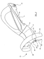
- Figure 6 shows a configuration of the trimming apparatus 2 with the cutting head 8 rotated through 180 degrees relative to the configuration shown in Figure 1.
- the guard means is still between the blade 46 and the user but the cutting edge 39 of the blade 46 is arranged to cut in a plane substantially perpendicular to the longitudinal axis of the handle rather than in a plane substantially parallel to the longitudinal axis of the handle as shown in Figure 1.
- the rotating means 54 is arranged to allow the cutting head 8 to be rotated around the axis of the rotating means 54 by nominally 180 degrees in either direction relative to the handle 4 from the configuration shown in Figure 1. That is, the largest angle through which the cutting head can be rotated relative to the handle is 360 degrees as would occur by rotation of the cutting head in either direction from the configuration in Figure 6, through the configuration shown in Figure 1 to form the configuration in Figure 6 again.
- the rotating means 54 prevents rotation of the cutting head 8 in excess of 180 degrees from the configuration shown in Figure 1 by means of an arrangement of a movable pin 58 and a stop 60, as shown in Figure 7.
- the trimming apparatus 2 When the trimming apparatus 2 is arranged in the configuration shown in Figure 1 (blade 46 arranged to cut in a plane substantially parallel to the handle 4) the movable pin 58 provided on one component 62 of the rotating means 54 and the stop 60 provided on another component 64 of the rotating means 54 are positioned opposite one another within the rotating means 54.
- Detents (not shown) hold the cutting head 8 in place relative to the handle 4 such that the stop 60 and the movable pin 58 are positioned opposite to one another in the configuration shown in Figure 1.
- the detents are in the form of a first hemispherical protrusion and a second hemispherical protrusion on a face of one component of the rotating means and a first complementary shaped recess and a second complementary shaped recess on an adjacent face of another component of the rotating means.
- the first hemispherical protrusion is positioned in the first complementary shaped recess
- the second hemispherical protrusion is positioned in the second complementary shaped recess.
- the first hemispherical protrusion and the first complementary shaped recess are positioned diametrically opposite the second hemispherical protrusion and the second complementary shaped recess about the axis of rotation of the rotating means.
- the detents are positioned equidistant from the axis of rotation of the rotating means.
- the movement of the pin 58 is limited to be within an arcuate region 66 within the portion 62 of the rotating means 54.
- the pin 58 is retained within the arcuate region 62 by means of arcuate retaining members in the region of opposite end portions of the pin 58. However, the retaining members permit the pin to freely move from one side of the region 66 to the other.
- the stop 60 is provided on the complementary portion 64 of the rotating means 54. The stop 60 is arranged such that rotation of the cutting head 8 relative to the handle 4 by 180 degrees anticlockwise as shown in Figure 7 brings the pin 58 and a first side 70 of the stop 60 into contact.
- the stop 60 is dimensioned such that it can pass between the opposing retaining members of the pin. Further rotation of the cutting head is prevented by the retaining members around the pin 58 when the pin 58 is in position 68A.
- Rotation of the stop 60 through the 180 degrees transforms the trimming apparatus 2 into the configuration shown in Figure 6 (blade 46 arranged to cut in a plane substantially perpendicular to the handle 4).
- the cutting head and the handle are held in the configuration shown in Figure 6 by means of the aforementioned detents.
- the first hemispherical protrusion is positioned in the second complementary shaped recess
- the second hemispherical protrusion is positioned in the first complementary shaped recess.
- the use of a pin fixed in position would mean that rotation of the first side 70 of the stop 60 relative to a fixed pin would allow rotation in one direction of 180 degrees, but rotation in a clockwise direction as shown in Figure 7 would be less than 180 degrees due to a second side 72 of the stop 60 opposite the first side 70 coming into contact with the pin 58.
- the stop 60 can be rotated through the extra degrees relating to the rotation of the width of the stop 60.
- the pin 58 will be moved a corresponding distance within the arcuate region 66 by contact between the second side 72 of the stop and the pin 58 until it is prevented by further movement by the retaining members associated with the pin 58 resulting in the pin 58 being in position 68B.
- the amount of movement of the pin 58 permitted by the retaining members is arranged to correspond to the movement required to compensate for the width of the stop 60, that is the distance between the first side 70 and the second side 72 of the stop.
- a channel 56 is provided in the rotating means through which electrical connections (not shown) pass between the battery pack 12 and the motor 28.
- the apparatus In use of the trimming apparatus 2 according to the present invention, the apparatus is placed close to a surface to be trimmed, such as an edge of a lawn or a shrub, and the button 24 is pressed, activating the micro switch 26, to energise the motor 28. Consequently, the rotating body 40 is rotated causing the blade 46 to be rotated and thus producing a circular cutting action in the region of the surface being trimmed.
- the cutting head 8 can be rotated relative to the handle 4 such that the plane of rotation of the blade 46 can be arranged to be substantially parallel with the surface to be trimmed.
- Any material extending from the surface for example weeds, grass or shoots, is cut by the blade 46 and separated from the surface.
- the shielding members 34 support both sides of the wrist of the user to prevent excessive wrist flexing and reduce possible straining of the user's wrist as movement of the trimming apparatus 2 relative to a surface can involve the flexing of a user's wrist to alter the direction of movement of the trimming apparatus.
- the positioning of the shielding members 34 both sides of the wrist of the user prevents the hand of the user coming into contact with sharp objects and stinging garden plants.
- a trimming apparatus has been described hereinbefore in which the battery pack 12 is removable for recharging. It should be appreciated that the battery pack 12 could be recharged whilst in the handle 4. It should also be appreciated that replaceable, non-rechargeable, batteries could be used to power the motor 28.
- trimming apparatus has been described as having a single blade, it should be appreciated that a plurality of blades, for example two opposing blades may be provided on a trimming apparatus in accordance with the present invention.
Landscapes
- Life Sciences & Earth Sciences (AREA)
- Environmental Sciences (AREA)
- Biodiversity & Conservation Biology (AREA)
- Ecology (AREA)
- Forests & Forestry (AREA)
- Harvester Elements (AREA)
- Details Of Cutting Devices (AREA)
Abstract
Description
Claims (12)
- A trimming apparatus comprising a handle means (4) and a cutting head (8), the cutting head (8) being attached directly to the handle means (4) and comprising a motor (28) and a rotatable cutting edge (39), characterised in that shielding means (34) adapted to protect a hand of a user is provided on the handle means (4) .
- A trimming apparatus as claimed in claim 1, characterised in that the handle means (4) contains at least one battery (12), for example a removable battery.
- A trimming apparatus as claimed in claim 2, characterised in that the at least one battery (12) is rechargeable, for example rechargeable whilst in the trimming apparatus or rechargeable by separate recharging means.
- A trimming apparatus as claimed in any preceding claim, characterised in that the rotatable cutting edge (39) is a blade, for example selected from plastics and metal material.
- A trimming apparatus as claimed in any one of claims 1 to 3, characterised in that the rotatable cutting edge (39) is a cutting wire, for example selected from plastics and metal material.
- A trimming apparatus as claimed in any preceding claim, characterised in that the rotatable cutting edge (39) is removable from the cutting head (8).
- A trimming apparatus as claimed in any preceding claim, characterised in that the rotatable cutting edge (39) is rotatable by the motor (28) to produce a cutting action.
- A trimming apparatus as claimed in any preceding claim, characterised in that rotating means (54) is provided between the handle means (4) and the cutting head (8), for example the rotating means (54) allows the cutting head (8) to rotate, preferably through an angle of 180 degrees, about an axis thereof relative to the handle means (4) such that the orientation of the plane of the rotatable cutting edge (39) relative to the handle can be changed.
- A trimming apparatus as claimed in claim 8, characterised in that the cutting head (8) is rotatable in either direction about the axis of the rotating means (54) relative to the handle means (4).
- A trimming apparatus as claimed in claim 8 or 9, characterised in that stop means (58, 60) are provided to prevent the cutting head (8) being rotated through more than 360 degrees about the axis of the rotating means (54) relative to the handle means (4).
- A trimming apparatus as claimed in any preceding claim, characterised in that the shielding means (34) are arranged to support a wrist of a user of the apparatus and are arranged to substantially protect a hand of the user from sharp objects.
- A trimming apparatus as claimed in any preceding claim, characterised in that the shielding means (34), preferably of convex form, are arranged to extend from the handle to both sides of the wrist of the user.
Applications Claiming Priority (2)
| Application Number | Priority Date | Filing Date | Title |
|---|---|---|---|
| GB0404726A GB2411565B (en) | 2004-03-03 | 2004-03-03 | Trimming apparatus |
| GB0404726 | 2004-03-03 |
Publications (2)
| Publication Number | Publication Date |
|---|---|
| EP1570720A2 true EP1570720A2 (en) | 2005-09-07 |
| EP1570720A3 EP1570720A3 (en) | 2005-12-21 |
Family
ID=32088601
Family Applications (1)
| Application Number | Title | Priority Date | Filing Date |
|---|---|---|---|
| EP05251232A Withdrawn EP1570720A3 (en) | 2004-03-03 | 2005-03-01 | Trimming apparatus |
Country Status (4)
| Country | Link |
|---|---|
| US (1) | US20050241156A1 (en) |
| EP (1) | EP1570720A3 (en) |
| CA (1) | CA2499158A1 (en) |
| GB (1) | GB2411565B (en) |
Families Citing this family (1)
| Publication number | Priority date | Publication date | Assignee | Title |
|---|---|---|---|---|
| JP4122484B2 (en) * | 2006-06-22 | 2008-07-23 | 伊東電機株式会社 | Mower |
Family Cites Families (22)
| Publication number | Priority date | Publication date | Assignee | Title |
|---|---|---|---|---|
| GB581504A (en) * | 1944-07-31 | 1946-10-15 | Albert Leonard Story | Improvements in rotary cutting devices particularly applicable for hedge trimming, grass-cutting and the like |
| US3710870A (en) * | 1971-08-19 | 1973-01-16 | Little Wonder Inc | Cordless electric hand tiller |
| US3711949A (en) * | 1971-09-15 | 1973-01-23 | J Doyel | Cordless electric garden trimmer with safety lock means |
| US3945116A (en) * | 1973-11-07 | 1976-03-23 | Hardin Jr John Ralph | Rotary shear with improved cutting assembly |
| DE8012962U1 (en) * | 1980-05-13 | 1980-08-14 | Max Langenstein, Feld- Und Gartengeraete Gmbh & Co, 7918 Illertissen | LAWN EDGE CUTTER |
| US4987681A (en) * | 1988-10-31 | 1991-01-29 | White Consolidated Industries, Inc. | Hand held cordless grass/weed trimmer |
| DE8909063U1 (en) * | 1989-07-26 | 1989-11-16 | Gardena Kress + Kastner Gmbh, 7900 Ulm | Plant trimmer, especially string trimmer |
| DE69709527T2 (en) * | 1996-11-08 | 2002-06-20 | Black & Decker Inc., Newark | Battery operated thread cutter |
| US6148523A (en) * | 1997-02-14 | 2000-11-21 | Ryobi North America, Inc. | Line feed mechanism for a line trimmer |
| SE509533C2 (en) * | 1997-06-25 | 1999-02-08 | Electrolux Ab | Device at cutting machine |
| EP0890302A1 (en) * | 1997-07-11 | 1999-01-13 | Scintilla Ag | Hedge trimmer |
| DE29718177U1 (en) * | 1997-10-14 | 1997-12-04 | Neumann, Hans, 69483 Wald-Michelbach | Accident protection shield for brush cutters and brushcutters |
| DE29824193U1 (en) * | 1997-10-14 | 2000-07-20 | Neumann, Hans, 69483 Wald-Michelbach | Accident prevention device for work equipment |
| DE19802007C1 (en) * | 1998-01-20 | 1999-11-11 | Wacker Werke Kg | Safety arrangement for the operating elements of a hand-held soil compaction roller |
| US6263979B1 (en) * | 1998-07-24 | 2001-07-24 | The Black & Decker Corporation | Interchangeable implement system for power tools |
| US6301866B1 (en) * | 1999-07-14 | 2001-10-16 | Black & Decker Inc. | Vegetation trimming and edging device with adjustable head orientation |
| GB2384678B (en) * | 2002-01-31 | 2004-01-21 | Paul Nicholas Pacey Lockton | Hedge trimming and shaping device |
| US6973728B2 (en) * | 2002-04-04 | 2005-12-13 | The Toro Company | Filament trimmer with dual triggers |
| GB2417406B (en) * | 2002-11-04 | 2006-05-10 | Husqvarna Uk Ltd | Trimmer |
| AU2004212920A1 (en) * | 2003-02-13 | 2004-09-02 | Black & Decker Inc. | Hand held scrubbing tool |
| GB2408924B (en) * | 2003-12-09 | 2005-10-26 | Grey Technology Ltd | Surface cleaning apparatus |
| DE202005001674U1 (en) * | 2005-02-03 | 2005-04-14 | Kmk Kunststoff- Und Montagetechnik Gmbh | Hand-guided garden implement with an electromotive drive system with multiphase motor |
-
2004
- 2004-03-03 GB GB0404726A patent/GB2411565B/en not_active Expired - Fee Related
-
2005
- 2005-02-28 US US11/066,298 patent/US20050241156A1/en not_active Abandoned
- 2005-03-01 EP EP05251232A patent/EP1570720A3/en not_active Withdrawn
- 2005-03-02 CA CA002499158A patent/CA2499158A1/en not_active Abandoned
Also Published As
| Publication number | Publication date |
|---|---|
| GB2411565B (en) | 2007-02-21 |
| US20050241156A1 (en) | 2005-11-03 |
| EP1570720A3 (en) | 2005-12-21 |
| GB0404726D0 (en) | 2004-04-07 |
| GB2411565A (en) | 2005-09-07 |
| CA2499158A1 (en) | 2005-09-03 |
Similar Documents
| Publication | Publication Date | Title |
|---|---|---|
| US4107841A (en) | Weed cutter construction | |
| US4641431A (en) | Hedge trimmer | |
| US4987681A (en) | Hand held cordless grass/weed trimmer | |
| US4089114A (en) | Cutting device | |
| US4823464A (en) | Grass trimmer | |
| US4177561A (en) | Rotary cutting assembly | |
| US4172322A (en) | Rotary cutting assembly | |
| US6769494B2 (en) | Combination line trimmer and edger | |
| US6105253A (en) | Hedge trimmer | |
| JP2013034404A (en) | Brush cutter | |
| US4067108A (en) | Rotary cutting assembly | |
| US5404644A (en) | Portable hand-held cultivator and trimmer | |
| EP1435194B1 (en) | Trimmer | |
| JP5282000B2 (en) | Extension handle used for gardening hair clippers | |
| JP2006314278A (en) | Brush cutter | |
| US6324764B1 (en) | Hedge trimmer assembly | |
| US6997268B2 (en) | Trimmer | |
| EP1570720A2 (en) | Trimming apparatus | |
| CN1732736B (en) | garden tool adjuster | |
| EP1188362A1 (en) | A string trimmer | |
| JP2012135256A (en) | Hand-held lawn mower | |
| JP5281999B2 (en) | Extension handle used for gardening hair clippers | |
| US4672744A (en) | Rotary trimmer | |
| US12490672B2 (en) | Lawn trimmer | |
| US3520120A (en) | Battery operated edger-trimmer and power scythe |
Legal Events
| Date | Code | Title | Description |
|---|---|---|---|
| PUAI | Public reference made under article 153(3) epc to a published international application that has entered the european phase |
Free format text: ORIGINAL CODE: 0009012 |
|
| AK | Designated contracting states |
Kind code of ref document: A2 Designated state(s): AT BE BG CH CY CZ DE DK EE ES FI FR GB GR HU IE IS IT LI LT LU MC NL PL PT RO SE SI SK TR |
|
| AX | Request for extension of the european patent |
Extension state: AL BA HR LV MK YU |
|
| PUAL | Search report despatched |
Free format text: ORIGINAL CODE: 0009013 |
|
| AK | Designated contracting states |
Kind code of ref document: A3 Designated state(s): AT BE BG CH CY CZ DE DK EE ES FI FR GB GR HU IE IS IT LI LT LU MC NL PL PT RO SE SI SK TR |
|
| AX | Request for extension of the european patent |
Extension state: AL BA HR LV MK YU |
|
| AKX | Designation fees paid | ||
| REG | Reference to a national code |
Ref country code: DE Ref legal event code: 8566 |
|
| STAA | Information on the status of an ep patent application or granted ep patent |
Free format text: STATUS: THE APPLICATION IS DEEMED TO BE WITHDRAWN |
|
| 18D | Application deemed to be withdrawn |
Effective date: 20060622 |