EP1570561B1 - Stromerzeugengssystem zur verbindung - Google Patents
Stromerzeugengssystem zur verbindung Download PDFInfo
- Publication number
- EP1570561B1 EP1570561B1 EP20030777335 EP03777335A EP1570561B1 EP 1570561 B1 EP1570561 B1 EP 1570561B1 EP 20030777335 EP20030777335 EP 20030777335 EP 03777335 A EP03777335 A EP 03777335A EP 1570561 B1 EP1570561 B1 EP 1570561B1
- Authority
- EP
- European Patent Office
- Prior art keywords
- interconnecting
- power
- utility power
- voltage phase
- phase
- Prior art date
- Legal status (The legal status is an assumption and is not a legal conclusion. Google has not performed a legal analysis and makes no representation as to the accuracy of the status listed.)
- Expired - Lifetime
Links
Images


Classifications
-
- H—ELECTRICITY
- H02—GENERATION; CONVERSION OR DISTRIBUTION OF ELECTRIC POWER
- H02J—ELECTRIC POWER NETWORKS; CIRCUIT ARRANGEMENTS OR SYSTEMS FOR SUPPLYING OR DISTRIBUTING ELECTRIC POWER; SYSTEMS FOR STORING ELECTRIC ENERGY
- H02J3/00—Circuit arrangements for AC mains or AC distribution networks
- H02J3/38—Arrangements for feeding a single network from two or more generators or sources in parallel; Arrangements for feeding already energised networks from additional generators or sources in parallel
- H02J3/388—Arrangements for the handling of islanding, e.g. for disconnection or for avoiding the disconnection of power
Definitions
- This invention relates to an interconnecting power generation system and, more particularly, to an interconnecting power generation system for supplying electrical power to an interconnecting load in conjunction with a utility power system.
- an interconnecting power generation system comprises an inverter apparatus for converting a DC output of a solar power generation system for example as a DC power source into an AC output and linking the DC power source to an AC utility power supply.
- a control unit for controlling the inverter apparatus has a detection circuit for detecting the phase voltage of the utility power supply, a detection circuit for detecting the output current of the inverter apparatus, an arithmetic circuit for calculating the error between signals indicating the phase voltage of the utility power supply and the output current of the inverter apparatus detected by the respective detection circuits, and a driver circuit for controlling the switching of the inverter apparatus based on the output of the arithmetic circuit, and makes the output current outputted from the current-controlled inverter apparatus follow the phase voltage signal of the utility power supply so that a sine wave current coincident in phase with the voltage of the utility power supply can be outputted.
- the interconnecting power generation system thereby converts electrical power generated by a solar cell into AC electrical power for example.
- Patent Document 1 JP-A-Hei11-285260 (Paragraph 0023, Fig. 1 )
- the interconnecting power generation system When an abnormality in the utility power supply such as an over-frequency or under-frequency condition is detected, the interconnecting power generation system must be isolated from the utility power system by opening the switch.
- an interconnecting power generation system comprising a turbogenerator
- the generator is put into a no-load operating condition to the rotational speed of the turbine rapidly increase to exceed the absolute rated speed, resulting in damage to the turbine or the auxiliaries.
- Patent Document 2 US-A-2001 0056 330 shows another example of interconnecting power generation system which, by detection of a power outage, disconnects the inverter from the utility power supply.
- the present invention has been made in view of the above circumstances and it is, therefore, an object of the present invention to provide an interconnecting power generation system which can detect an abnormality in the utility power supply and can be isolated from the utility power system and can prevent damage to a turbogenerator.
- an interconnecting power generation system 1 connected in parallel to a utility power system 10 for supplying electrical power to an interconnecting load 12, comprising: an interconnecting inverter 14 for linking generated electrical power to the utility power system 10; a voltage phase shift circuit 20 which synchronizes the output voltage phase of the interconnecting inverter 14 with the utility power voltage phase and monitors zero crossings of the utility power voltage, namely points at which the utility power voltage (alternating voltage waveform) crosses the zero-volt line, and which, when a predetermined number of zero crossings have been detected or when a zero crossing of the utility power voltage is detected after an internal timer has reached a predetermined period of time, with the zero crossing timing as a starting point, shifts the output voltage phase from the utility power voltage phase during one cycle and shifts the shifted output voltage phase to the utility power voltage phase during the following cycle; a circuit breaker 22 for shutting off the output of the interconnecting
- the phase is shifted reliably for a period of two cycles of an advanced phase and a delayed phase, with the zero crossing timing as a starting point.
- the interconnection control unit 30 can detect the power outage irrespective of the load condition using the comparison result of the phases during the period of two cycles of the advanced phase and the delayed phase. Namely, the interconnection control unit 30 can detect certainly the power outage in the second cycle even if the phase is delayed according to the load condition.
- the interconnection control unit 30 can detect a power outage caused by an interruption of power supply from the utility power system 10 based on a series of the predetermined number of matching signals outputted from the phase comparator 24 and send a control signal to the circuit breaker 22 to shut off the output of the interconnecting inverter 14 from the utility power system 10.
- the interconnection control unit 30 detects variations in the frequency of the utility power system 10 and sends a control signal to the circuit breaker 22 to shut off the output of the interconnecting inverter 14 from the utility power system 10.
- the interconnection control unit 30 can detect variations in the frequency of the utility power system 10 and can shut off the output of the interconnecting inverter from the utility power system 10 by sending a control signal to the circuit breaker 22.
- an interconnecting power generation system 1 connected in parallel to a utility power system 10 and for supplying electrical power to an interconnecting load 12, comprising: a turbogenerator 32 for generating electrical power, an interconnecting inverter 14 for linking electrical power generated by the turbogenerator 32 to the utility power system 10; a voltage phase shift circuit 20 which synchronizes the output voltage phase of the interconnecting inverter 14 with the utility power voltage phase and monitors zero crossings of the utility power voltage, and which, when a predetermined number of zero crossings have been detected, shifts the output voltage phase from the utility power voltage phase during one cycle and shifts the shifted output voltage phase to the utility power voltage phase during the following cycle; a circuit breaker 22 for shutting off the output of the interconnecting inverter 14 from the utility power system 10; a phase comparator 24 for comparing the voltage phase of the utility power system 10 and the output voltage phase of the interconnecting
- the interconnection control unit 30 can detect a power outage caused by an interruption of power supply from the utility power system 10 based on a series of the predetermined number of matching signals outputted from the phase comparator 24 and send a control signal to the circuit breaker 22 to shut off the output of the interconnecting inverter 14 from the utility power system 10, and can decrease the rotational speed of the turbogenerator 32 to the predetermined speed during the period between the detection of the power outage and the shutoff of the utility power system 10.
- an interconnecting power generation system 1 connected in parallel to a utility power system 10 and for supplying electrical power to an interconnecting load 12, comprising: a turbogenerator 32 for generating electrical power, an interconnecting inverter 14 for linking electrical power generated by the turbogenerator 32 to the utility power system 10; a voltage phase shift circuit 20 which synchronizes the output voltage phase of the interconnecting inverter 14 with the utility power voltage phase and monitors zero crossings of the utility power voltage, and which, when a predetermined number of zero crossings have been detected, shifts the output voltage phase from the utility power voltage phase during one cycle and shifts the shifted output voltage phase to the utility power voltage phase during the following cycle; a circuit breaker 22 for shutting off the output of the interconnecting inverter 14 from the utility power system 10; a phase comparator 24 for comparing the voltage phase of the utility power system 10 and the output voltage phase of the interconnecting
- the interconnection control unit 30 can detect a power outage caused by an interruption of power supply from the utility power system 10 based on a series of the predetermined number of matching signals outputted from the phase comparator 24 and send a control signal to the circuit breaker 22 to shut off the output of the interconnecting inverter 14 from the utility power system 10, and can send a shutoff command to the turbogenerator 32 to stop the operation of the turbogenerator 32 after allowing the turbine 36 to rotate at the rated rotational speed for the predetermined period of time.
- the turbogenerator 32 recharges a battery 38 within the predetermined period of time in response to the shutoff command.
- Fig. 1 through Fig. 6 are drawings for illustrating the embodiments for carrying out the invention.
- those sections with the same or similar reference numerals indicate the same or equivalent items and redundant descriptions are omitted.
- FIG. 1 is a block diagram of an interconnecting power generation system according to a first embodiment of the present invention.
- An interconnecting power generation system 1 comprises a rectifier 42 connected to a stator winding 40 of a turbogenerator 32, an interconnecting inverter 14 connected to the rectifier 42 via a DC bus 45, a smoothing capacitor 43 connected in parallel to the DC bus 45, a battery 38 as electricity storage means connected to the DC bus 45 via a DC/DC converter 44 as DC voltage converting means, a circuit breaker 22 connected to the output of the interconnecting inverter 14, and a control unit 2 connected individually to the circuit breaker 22, an AC power line 46, the interconnecting inverter 14, and the turbogenerator 32 for controlling the interconnecting power generation system 1.
- the control unit 2 comprises a phase comparator 24 connected to the AC power line 46, a zero crossing monitor 16 connected to the AC power line 46, a phase locked loop circuit (PLL) 49 as phase synchronization loop means connected to the zero crossing monitor 16, a clock circuit 50 connected to the PLL 49, a voltage phase shift circuit 20 connected to the zero crossing monitor 16 via a counter 18 and connected to the clock circuit 50, a sine wave generating circuit 51 connected to the voltage phase shift circuit 20, a pulse width modulation circuit 52 having an input connected to the sine wave generating circuit 51 and an output (or outputs) connected to the interconnecting inverter 14 and connected to the phase comparator 24, and a control section 30 as an interconnection control apparatus having an input connected to the phase comparator 24 and an output (or outputs) for outputting a circuit breaker control signal to the circuit breaker 22 through a line 28 and a turbine control command to the turbogenerator 32 through a line 34.
- PLL phase locked loop circuit
- the turbogenerator 32 has a gas turbine 36 to which a permanent magnet rotor (connected to the turbogenerator 32) is commonly connected and which is rotated by combustion gas generated by burning fuel with air, a stator winding 40 surrounding the permanent magnet rotor connected to the gas turbine 36, and an exhaust port 41 for discharging the combustion gas.
- the interconnecting power generation system 1 is connected in parallel to a utility power system 10 via the AC power line 46 and supplies AC electrical power with voltage and frequency of, for example, 400V/50Hz, 200V/50Hz, or 100V/50Hz to an interconnecting load 12. It is needless to mention that the voltage and frequency of the AC electrical power can be adjusted to those of the electrical power supplied in the region where the interconnecting power generation system 1 is installed.
- turbogenerator 32 When the turbogenerator 32 receives a start command from the control section 30 through the line 34, DC electrical power is supplied from the battery 38 to a start inverter (not shown), which applies AC electrical power to the stator winding 40 to generate torque in the permanent magnet rotor to start the gas turbine 36.
- a start inverter (not shown), which applies AC electrical power to the stator winding 40 to generate torque in the permanent magnet rotor to start the gas turbine 36.
- the start inverter When the supply of fuel and air and the ignition condition are controlled and the gas turbine 36 establishes self-operation, the start inverter is shut off from the stator winding 40 and supplies three-phase AC electrical power to the rectifier 42 connected to the stator winding 40.
- the rectifier 42 supplies DC electrical power to the DC bus 45 connected to its output charging the smoothing capacitor 43 connected in parallel to the DC bus 45 to stabilize the potential of the DC bus 45.
- the rectifier 42 also supplies DC electrical power to the interconnecting inverter 14 through the DC bus 45.
- the DC electrical power supplied from the rectifier 42 may be boosted by a DC/DC converter (not shown) may be supplied to the interconnecting inverter 14.
- the interconnecting inverter 14 has three pairs of IGBT (Insulated Gate Bipolar Transistor) switching transistors which are driven complementarily, and generates pulse-width-modulated sine wave AC voltage which follows the voltage phase of the utility power system 10 by switching on/off the DC voltage supplied from the DC bus 45 with a pulse width modulation (PWM) control signal.
- IGBT Insulated Gate Bipolar Transistor
- the phase comparator 24 and the zero crossing monitor 16 are connected in parallel to the AC power line 46.
- the phase comparator 24 detects the voltage phase of the utility power system 10 which appears in the AC power line 46 and receives an output signal for driving the interconnecting inverter 14 from the pulse width modulation circuit 52.
- the phase comparator 24 compares the detected voltage phase of the utility power system 10 and the output signal from the interconnecting inverter 14 and compare the output voltage phase of the interconnecting inverter 14 and the voltage phase of the utility power system 10 in a pseudo manner.
- the comparison result and a voltage phase signal of the AC power line 46 are outputted to the control section 30 through a line 26.
- the control section 30 controls the whole interconnecting power generation system 1.
- the control section 30 can prevent the interconnecting power generation system 1 from operating independently since the control section opens (shuts off) the circuit breaker 22 by sending a control signal to the circuit breaker 22 through the line 28 to isolate the interconnecting inverter 14 from the utility power system 10 when the voltage phase of the utility power system 10 is determined to have a frequency which exceeds or falls short of the frequency of the output voltage phase of the interconnecting inverter 14 by approximately 2% or greater based on the comparison result by the phase comparator 24.
- the control section 30 determines that the frequency of the voltage of the utility power system 10 is excessively high or low, and opens (shuts off) the circuit breaker 22 to isolate the interconnecting inverter 14 from the utility power system 10.
- the interconnecting power generation system 1 configured in this way can be thus isolated within at most several hundreds ms, preferably within 0.2 seconds.
- the zero crossing monitor 16 monitors zero crossings of the voltage phase of the AC power line 46 via a line 47.
- the zero crossing monitor 16 monitors the zero crossing timing at which the voltage waveform of the AC power line 46 passes a reference potential (ground potential) and outputs a zero crossing detection signal to the counter 18 every time it detects a zero crossing. Counting the zero crossing detection signals allows determining one cycle of the voltage waveform of the AC power line 46. For example, three zero crossing detection signals can be counted as one cycle of a sine wave voltage waveform.
- the zero crossing monitor 16 sends a waveform signal to the PLL 49 through the line 48.
- the PLL 49 is an electronic circuit for making the frequency of an output signal to coincide with the frequency of an input signal or a reference frequency.
- the PLL 49 detects the phase difference between the input signal and the output signal and generates a signal having a frequency accurately synchronized with the frequency of the input signal or the reference frequency by controlling a VCO (an oscillator that controls the frequency according to the voltage) or a loop of its internal circuit.
- VCO an oscillator that controls the frequency according to the voltage
- the voltage phase shift circuit 20 is configured to divide the frequency of the clock circuit 50 so that it can make the output voltage phase of the interconnecting inverter 14 coincide with the voltage phase of the utility power system 10 according to the output of the PLL 49.
- the voltage phase shift circuit 20 also receives a voltage phase shift signal from the counter 18 when it has counted a predetermined number of zero crossings or when it has counted a zero crossings after an internal timer (not shown) has reached a predetermined period of time.
- the voltage phase shift circuit 20 changes the frequency division ratio of the clock circuit 50 (delays or advances the phase of the clock), with the zero crossing timing as a starting point, and outputs a changed clock signal to the sine wave generating circuit 51.
- the sine wave generating circuit 51 sends a sine wave with a shifted voltage phase to the pulse width modulation circuit 52.
- the pulse width modulation circuit 52 drives the interconnecting inverter 14 to shift the output voltage phase from the voltage phase of the utility power system 10.
- the voltage phase shift circuit 20 receives a voltage phase shift signal from the counter 18 every 100 ms and sets the frequency division ratio of the clock circuit 50 with the zero crossing timing as a starting point to cause a phase delay (minus phase shift) in response to the voltage phase shift signal. After the output voltage phase of the interconnecting inverter 14 has been shifted during one cycle, the voltage phase shift circuit 20 resets the frequency division ratio of the clock circuit 50 to cause a phase advance (plus phase shift) to return the output voltage phase to the initial state, whereby one phase shifting operation is completed.
- the phase comparator 24 does not detect the shift in the voltage phase.
- the control section 30 can compare the voltage phase received from the phase comparator 24 with the normal output voltage phase to detect a change in the voltage phase.
- the phase shift amount is determined based on the time difference in the zero crossing timing of the voltage phase.
- the phase is shifted reliably for a period of two cycles of an advanced phase and a delayed phase, with the zero crossing timing as a starting point.
- the interconnection control unit 30 can detect the power outage irrespective of the load condition using the comparison result of the phases during the period of two cycles of the advanced phase and the delayed phase.
- the interconnecting power generation system 1 can be isolated within at most several hundreds ms, preferably within 0.5 seconds in this way.
- the delayed or advanced voltage phase is detected during the period of two cycles.
- the phase difference may also be detected for a period of one half or full cycle (in this case, the phase difference can be detected during the cycle in which the phase is changed into the same direction as the direction of the phase change according to the load state predetermined or in which the phase change according to the load state is little, for example).
- an increase or decrease in the frequency which may occur during the period of two cycles may be detected for achieving the same effect.
- description has been made above of a method in which the phase is shifted over two cycles it will be appreciated that another method may be used for achieving the same effect in which the phase is shifted over more than two cycles for the detection.
- the order of the advanced and delayed phases during the period of two cycles may be reversed.
- the interconnecting power generation system is configured using a hardware logic as described above in this embodiment, the present invention is not limited to the above configuration.
- the same effect can be obtained when the phase comparison, zero crossing monitoring, pulse width modulation and digital PLL are performed by software processing using a microcomputer or a digital signal processor and the processing operation is performed after converting the voltage phase of the AC power line 46 into a digital signal by an A/D converter (not shown).
- the control section 30 When the control section 30 detects any one of an under-frequency or over-frequency condition or a power outage, the control section 30 sends a turbine control command through the line 34 to decrease the rotational speed of the gas turbine 36. Since the gas turbine 36 is operated at a rotational speed which is lower than the rated speed, the rotational speed of the gas turbine 36 does not increase to the absolute rated speed with the turbogenerator 32 at no-load condition even when the circuit breaker 22 is opened immediately after (approximately 0.2 to 0.5 seconds after) the detection to isolate the interconnecting power generation system 1 from the utility power system 10.
- the control section 30 also sends a shutoff command to the turbogenerator 32 through the line 34 to control the rotational speed of the gas turbine 36 to be returned to the rated speed. Then, the control section 30 allows the gas turbine 36 to rotate at the rated speed for a predetermined period of time and then stops the operation of the turbogenerator 32. Since the rotational speed of the gas turbine 36, which have once increased because of the no-load operation, returns to the rated speed, the circuit breaker 22 can be closed (turned on) to link the interconnecting power generation system 1 with the utility power system 10 again when the normal power supply is restored after a short period of work during the power outage.
- the turbogenerator 32 is stopped leaving the circuit breaker 22 opened (turned off).
- the auxiliaries can be completely cooled down.
- control section 30 When the control section 30 detects any one of an over-frequency or under-frequency condition or a power outage, the control section 30 controls the battery 38 to be charged from the DC bus 45 through the DC/DC converter 44.
- the charging time of the battery 38 is preferably set to a period of any length by the time the turbogenerator 32 is stopped.
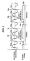
- Fig. 2 is a waveform graph showing the output of the interconnecting power generation system 1 according to the first embodiment of the present invention.
- the interconnecting power generation system outputs a voltage waveform 56 from the interconnecting inverter to the AC power line 46.
- the voltage waveform 56 shown by a solid line in the graph indicates any one of three-phase AC outputs (u, v, w).
- the voltage waveform 56 shown by a broken line indicates a normal AC waveform (non-shifted waveform).
- the control section 30 receives a shift signal 57 from the counter 18 and monitors the comparison result between the phase of the voltage waveform from the interconnecting inverter 14 shown by a solid line and that of the utility power system voltage waveform shown by a broken line.
- the voltage phase shift circuit 20 (see Fig. 1 ) synchronizes the frequency F ⁇ Hz and phase of the voltage waveform 56 as the output of the interconnecting inverter 14 with the frequency and phase of the utility power voltage and monitors zero crossings of the utility power voltage.
- the voltage phase shift circuit 20 delays the output voltage phase of the voltage waveform 56 within one cycle (20 ms) (which results in the frequency thereof to be shifted from the frequency F of the utility power voltage to the frequency (F + ⁇ f)). Then, the voltage phase shift circuit 20 advances the output voltage phase of the voltage waveform 56 within the next one cycle (20 ms) (which results in the frequency thereof to be shifted from the frequency F of the utility power voltage to the frequency (F - ⁇ f)).
- control section 30 can perform frequency shifting , which results from the phase shifting starting every 100 ms at the zero crossing point.
- the period of two cycles starting at the zero crossing point, during which the phase of the voltage waveform is changed, will be referred to as frequency shifting period.
- the illustrated voltage waveform 56 is synchronized with the frequency F of the utility power voltage except for the frequency shifting period .
- a frequency shifting period is started at a zero crossing point 55 which appears immediately after the falling edge 58 of the shift signal 57 and the frequency of the voltage waveform 56 is increased by ⁇ f (Hz).
- the shift signal 57 is activated and a zero crossing point 53 which appears one cycle after the zero crossing point 55 is detected, and data on the shifted waveform with the increased frequency is captured. Since the voltage waveform 56 shown by a solid line is advanced in phase with respect to the normal voltage waveform shown by a broken line, the utility power system 10 is interrupted and the AC power line 46 is also interrupted.
- the control unit 2 can control the circuit breaker 22 to be opened.
- the frequency of the voltage waveform 56 is decreased by ⁇ f (Hz) at the zero crossing point 53 to return it to the normal frequency F.
- ⁇ f Hz
- a zero crossing point 54 which appears one cycle after the zero crossing point 53 is detected and data on the shifted waveform with the decreased frequency is captured.
- the frequency F of the voltage waveform 56 at this point of time is synchronized with the utility frequency.
- a frequency shifting period as described above is started again in response to a falling edge 58a which deactivates the shift signal 57, which has been activated, 100 ms after the falling edge 58 of the shift signal 57.
- data on the shifted waveform with the increased frequency is captured at a zero crossing point 53a to detect a power outage in the AC power line 46.
- the circuit breaker 22 may be opened not at the first detection of the power outage but in response to the second detection of the power outage.
- the frequency of the voltage waveform 56 is decreased by ⁇ f (Hz) at the zero crossing point 53a.
- a zero crossing point 54a which appears one cycle after the zero crossing point 53a is detected and data on the shifted waveform with the decreased frequency is captured.
- the frequency F of the voltage waveform 56 at this point of time is synchronized with the utility frequency.
- a frequency shifting period can be started in response to a falling edge 58b of the shift signal 57 100 ms after the falling edge 58a.
- the voltage waveform 56 has been described above as a waveform at the time of a power outage shown by a solid line, when the utility power system 10 is normally supplying electrical power, the frequency of the voltage waveform 56 in the AC power line 46 is changed to the frequency of the voltage waveform shown by a broken line even if a shifted voltage waveform is outputted from the interconnecting inverter 14.
- Fig. 3 is a flowchart illustrating passive independent operation detection of the interconnecting power generation system according to the first embodiment of the present invention.
- the interconnecting power generation system performs passive independent operation detection.
- the process proceeds to the step 61, where the interconnecting power generation system performs active independent operation detection.
- the step 61 it is determined whether the detected frequency of the voltage which appears in the AC power line 46 during the frequency shifting period is higher or lower than the reference frequency. For example, when the utility frequency is 50 Hz and the frequency shift amount is set to 1 Hz, an over-frequency or under-frequency can be detected with a detection level of ⁇ 2%.
- the process proceeds to the step 62, where an active timer is initialized (reset to zero). Then, the process proceeds to the step 63, where the process is ended. If the determined result is positive (YES), the process proceeds to the step 64, where it is determined whether or not an active detection time has elapsed.
- the process proceeds to the step 65, where passive independent operation is detected and the circuit breaker 22 is opened. Then, the process proceeds to the step 63, where the process is ended.
- the process proceeds to the step 66, where the active timer is incremented. Then, the process proceeds to the step 63, where the process is ended.
- an over frequency or an under frequency can be detected at any times with a detection level of ⁇ 2%.
- the detection level of the frequency shift is set to 1/2 of the shift frequency, for example, when the frequency of the utility power system 10 is 50 Hz and the frequency shift amount is set to 1 Hz, a frequency shift is detected when the frequency is 50.5 Hz or higher at the time when the frequency is increased. Also under the same conditions, a frequency shift is detected when the frequency is 49.5 Hz or lower at the time when the frequency is decreased.
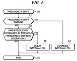
- Fig. 4 is a flowchart illustrating active independent operation detection of the interconnecting power generation system according to the first embodiment of the present invention.
- the interconnecting power generation system starts active independent operation detection in the step 70. Then, the process proceeds to the step 71, where it is determined whether or not it is during the frequency shifting period.
- the process proceeds to the step 74, where the internal PLL is advanced to increase the frequency. Then, the process proceeds to the step 73, where the process is ended. If the determined result is negative (NO), the process proceeds to the step 72, where it is determined whether or not the frequency was increased (plus shift) in the previous frequency shifting operation. If the determined result is positive (YES), the process proceeds to the step 75, where the internal PLL is delayed to decrease the frequency. Then; the process proceeds to the step 73, where the process is ended. When the determined result is negative (NO) at the step 72, the process proceeds to the step 73, where the process is ended.
- the active independent operation detection process is repeated to shift the frequency at intervals of about 100 ms.
- the voltage waveform which appears in the AC power line 46 is monitored so that a power outage in the utility power system 10 can be detected.
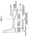
- Fig. 5 is a graph for illustrating the operation of an interconnecting power generation system according to a second embodiment of the present invention.
- the turbogenerator 32 decreases the supply of fuel and air to decrease the rotational speed 76 of the gas turbine 36 within 30 seconds from the rated rotational speed to a low rotational speed in preparation for stopping it.
- the control section 30 sends a charging start command 79 for controlling the DC/DC converter 44 to charge the battery 38. While the gas turbine 36 is rotating at the decreased speed, the charging of the battery 38 is complete (80) within about 15 minutes. Then, the control section 30 stops the supply of fuel and air to the gas turbine 36 to stop the combustion in the gas turbine 36.
- Cooling of the auxiliaries and circulating oil is complete (81) about 10 minutes after the battery charging has been complete (80), and the gas turbine 36 can be stopped completely.
- the shutoff command 78 is outputted, the turbine exhaust temperature 77 is the rated value. Then the rotational speed of the gas turbine 36 decreases in response to the shutoff command 78 to increase the turbine exhaust temperature 77,but the increased temperature is still within a permissible value. Then the combustion in the gas turbine 36 is stopped and the turbine exhaust temperature 77 gradually decreases and the cooling is complete (81).
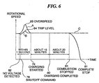
- Fig. 6 is a graph for illustrating the operation of an interconnecting power generation system according to a third embodiment of the present invention.
- the interconnecting power generation system sends a turbine deceleration command to the turbogenerator 32 when the control section 30 has detected a power outage (82).
- the turbogenerator 32 decreases the supply of fuel and air to decelerate the gas turbine 36 to a lower rotational speed than its rated speed.
- the control section 30 sends a shutoff command 78 within about 1 second after the power outage detection (82) to open the circuit breaker 22 isolating the interconnecting power generation system from the utility power system 10. Since the turbogenerator 32 is put into a no-load operating condition by the isolation, the rotational speed of the gas turbine 36 increases to a trip level 84 as indicated by B. However, the rotational speed does not reach an overspeed 83, such as when the isolation is made when the gas turbine 36 is operating at the rated speed as indicated by A because of lower rotational speed of the gas turbine 36.
- the turbogenerator 32 controls the supply of fuel and air to return the rotational speed of the gas turbine 36 from the trip level 84 to its rated speed. After the rotational speed of the gas turbine 36 has been returned to the rated speed, charging of the battery 38 is started (79). The charging of the battery 38 is complete in about 15 minutes (80).
- the turbogenerator 32 is operated for about another 20 minutes, during which the voltage of the AC power line 46 is monitored to detect power restoration of the utility power system 10.
- the combustion in the gas turbine 36 is stopped (81) and the turbine speed is gradually decreased until the turbogenerator stops completely (81).
- the interconnecting power generation system can avoid independent operation by detecting an abnormality in the utility power system 10 and can prevent damage to and deterioration of the turbogenerator 32.
- an interconnecting power generation system which can detect an abnormality in the utility power supply and can be isolated from the utility power a system and can prevent damage to a turbogenerator.
Landscapes
- Engineering & Computer Science (AREA)
- Power Engineering (AREA)
- Supply And Distribution Of Alternating Current (AREA)
Claims (5)
- Ein Verbindungs- bzw. Zusammenschaltungsleistungserzeugungssystem, das parallel verbunden ist mit einem Energieversorgungsleistungssystem (10) zum Liefern elektrischer Energie an eine verbundene Last (12), wobei das Leistungserzeugungssystem aufweist:einen Verbindungsinverter (14) zum Verbinden erzeugter elektrischer Leistung mit dem Energieversorgungsleistungssystem (10);eine Spannungsphasenschiebeschaltung (20), die die Ausgangsspannungsphase von dem Verbindungsinverter mit der Energieversorgungsleistungsspannungsphase synchronisiert und Null-Durchgänge von der Energieversorgungsleistungsspannung überwacht, und die, wenn eine vorherbestimmte Anzahl von Null-Durchgängen detektiert worden ist, die Ausgangsspannungsphase von der Energieversorgungsleistungsspannungsphase während einem Zyklus schiebt und die geschobene Ausgangsspannungsphase zu der Energieversorgungsleistungsspannungsphase während dem nachfolgenden Zyklus schiebt;einen Trennschalter (22) zum Abschalten des Ausgangs von dem Verbindungsinverter von dem Energieversorgungsleistungssystem;einen Phasenkomparator (24) zum Vergleichen der Spannungsphase von dem Energieversorgungsleistungssystem und der Ausgangsspannungsphase von dem Verbindungsinverter; undeine Verbindungssteuereinheit, die einen Energieausfall detektiert, verursacht durch eine Unterbrechung der Leistungs- bzw. Energieversorgung von dem Energieversorgungsleistungssystem basierend auf einer Reihe von einer vorherbestimmten Anzahl von Abgleichsignalen, ausgegeben von dem Phasenkomparator, und ein Steuersignal an den Trennschalter sendet zum Abschalten des Ausgangs von dem Verbindungsinverter von dem Energieversorgungsleistungssystem.
- Verbindungsleistungserzeugungssystem gemäß Anspruch 1, wobei, wenn kein Abgleichsignal von dem Phasenkomparator innerhalb einer Periode ausgeben wird, während der die Ausgangsspannungsphase mit der Energieversorgungsleistungsspannungsphase abzugleichen ist, die Verbindungssteuereinheit Variationen in der Frequenz von dem Energieversorgungsleistungssystem detektiert und ein Steuersignal an den Trennschalter sendet zum Abschalten des Ausgangs von dem Verbindungsinverter von dem Energieversorgungsleistungssystem.
- Ein Verbindungsleistungserzeugungssystem gemäß Anspruch 1, das ferner aufweist:einen Turbogenerator (32) zum Erzeugen elektrischer Leistung, wobei die Verbindungssteuereinheit die Rotationsgeschwindigkeit von dem Turbogenerator auf eine vorherbestimmte Geschwindigkeit reduziert undzwar während der Periode zwischen der Detektion von dem Leistungs- bzw. Energieausfall und dem Abschalten von dem Energieversorgungsleistungssystem.
- Ein Verbindungsleistungserzeugungssystem gemäß Anspruch 1, das ferner aufweist:einen Turbogenerator (32) zum Erzeugen elektrischer Energie bzw. Leistung, wobei der Turbogenerator eine Turbine (36) besitzt,wobei die Verbindungssteuereinheit ein Abschaltkommando an den Turbogenerator sendet zum Stoppen des Betriebs von dem Turbogenerator und zwar nach dem es der Turbine erlaubt ist, mit der Nennrotationsgeschwindigkeit für eine vorherbestimmte Zeitperiode zu rotieren.
- Ein Verbindungsleistungserzeugungssystem gemäß Anspruch 3 oder Anspruch 4, wobei der Turbogenerator eine Batterie (38) wiederauflädt und zwar innerhalb der vorherbestimmten Zeitperiode ansprechend auf das Abschaltkommando.
Applications Claiming Priority (3)
| Application Number | Priority Date | Filing Date | Title |
|---|---|---|---|
| JP2002357778 | 2002-12-10 | ||
| JP2002357778 | 2002-12-10 | ||
| PCT/JP2003/015649 WO2004054081A2 (en) | 2002-12-10 | 2003-12-08 | Interconnecting power generation system |
Publications (2)
| Publication Number | Publication Date |
|---|---|
| EP1570561A2 EP1570561A2 (de) | 2005-09-07 |
| EP1570561B1 true EP1570561B1 (de) | 2010-04-14 |
Family
ID=32500871
Family Applications (1)
| Application Number | Title | Priority Date | Filing Date |
|---|---|---|---|
| EP20030777335 Expired - Lifetime EP1570561B1 (de) | 2002-12-10 | 2003-12-08 | Stromerzeugengssystem zur verbindung |
Country Status (5)
| Country | Link |
|---|---|
| US (1) | US7233082B2 (de) |
| EP (1) | EP1570561B1 (de) |
| AU (1) | AU2003286426A1 (de) |
| DE (1) | DE60332151D1 (de) |
| WO (1) | WO2004054081A2 (de) |
Families Citing this family (27)
| Publication number | Priority date | Publication date | Assignee | Title |
|---|---|---|---|---|
| JP2005042684A (ja) * | 2003-07-25 | 2005-02-17 | Denso Corp | 電動機付ターボチャージャの電力制御装置および電動ターボチャージャ装置 |
| US7417336B2 (en) * | 2004-08-31 | 2008-08-26 | Caterpillar Inc. | Combination current hysteresis and voltage hysteresis control for a power converter |
| US7362600B2 (en) * | 2004-10-01 | 2008-04-22 | Continental Automotive Systems Us, Inc. | Method and apparatus for cycle error correction for a power converter device, such as an electronic power inverter |
| DE102006017479A1 (de) * | 2006-04-13 | 2007-10-18 | Siemens Ag Österreich | Verfahren zum Messen eines mittels Wechselrichter erzeugten Wechselstromes und Anordnung zur Durchführung des Verfahrens |
| DE102006032736A1 (de) * | 2006-07-14 | 2008-01-17 | Robert Bosch Gmbh | Generatorvorrichtung mit aktivem Load dump-Schutz |
| EP2118449B1 (de) * | 2007-02-14 | 2018-11-28 | General Electric Technology GmbH | Kraftwerksanlage mit einem verbraucher sowie verfahren zu deren betrieb |
| DE502008000599D1 (de) * | 2007-02-14 | 2010-06-10 | Alstom Technology Ltd | Verfahren zum betrieb einer kraftwerksanlage |
| JP5473610B2 (ja) * | 2007-02-14 | 2014-04-16 | アルストム テクノロジー リミテッド | 発電装置および発電装置の駆動方法 |
| DE102007007913A1 (de) * | 2007-02-14 | 2008-08-21 | Alstom Technology Ltd. | Verfahren zum Betrieb einer Kraftwerksanlage |
| JP2009059662A (ja) * | 2007-09-03 | 2009-03-19 | Mitsubishi Electric Corp | 電力開閉装置およびその制御方法 |
| US7612466B2 (en) * | 2008-01-28 | 2009-11-03 | VPT Energy Systems | System and method for coordinated control and utilization of local storage and generation, with a power grid |
| JP2011036040A (ja) * | 2009-07-31 | 2011-02-17 | Renesas Electronics Corp | 系統連系システム及び系統連系方法 |
| US9118213B2 (en) | 2010-11-24 | 2015-08-25 | Kohler Co. | Portal for harvesting energy from distributed electrical power sources |
| DE102011000394A1 (de) * | 2011-01-28 | 2012-08-02 | Sma Solar Technology Ag | Lokale Energieversorgungsanlage |
| JP6047442B2 (ja) | 2013-03-29 | 2016-12-21 | 富士電機株式会社 | 給電装置 |
| JP6124336B2 (ja) * | 2013-06-12 | 2017-05-10 | 東海旅客鉄道株式会社 | 給電装置 |
| US10140309B2 (en) * | 2014-06-10 | 2018-11-27 | Alfresco Software, Inc. | File tracking on client machines synchronized with a content management system repository |
| EP3079217A1 (de) | 2015-04-09 | 2016-10-12 | ABB Technology AG | Verfahren zur erkennung von inselbildung in netzangeschlossenen stromerzeugungssystemen und zugehörige gleichstrom-wechselstrom-wandlervorrichtung |
| KR101739181B1 (ko) | 2015-04-27 | 2017-05-23 | 엘에스산전 주식회사 | 에너지 저장 시스템 |
| US9912158B2 (en) * | 2016-03-16 | 2018-03-06 | Schweitzer Engineering Laboratories, Inc. | Decentralized generator control |
| US9906041B2 (en) * | 2016-03-16 | 2018-02-27 | Schweitzer Engineering Laboratories, Inc. | Decentralized generator control |
| US10063242B2 (en) * | 2016-12-08 | 2018-08-28 | National Chung Shan Institute Of Science And Technology | Phase-locked loop method for use in utility electricity parallel-connection system |
| US10381835B1 (en) | 2018-02-09 | 2019-08-13 | Schweitzer Engineering Laboratories, Inc. | Electric power generator selection, shedding, and runback for power system stability |
| TWM567997U (zh) * | 2018-07-02 | 2018-10-01 | 孔明電機股份有限公司 | 電動機系統及其高頻諧波抑制裝置 |
| JP6935528B2 (ja) * | 2020-03-02 | 2021-09-15 | 浜松ホトニクス株式会社 | 静電チャック装置用電源、静電チャック装置、及びデチャック制御方法 |
| EP4406081A1 (de) * | 2021-09-22 | 2024-07-31 | Flexgen Power Systems, Inc. | Elektrische systeme und verfahren mit einem lokalen bus mit hoher kapazität, unterstützt durch energiespeicherung |
| DE102022104015B4 (de) * | 2022-02-21 | 2023-08-31 | Sma Solar Technology Ag | Inselnetzerkennung spannungseinprägender Wechselrichter und Wechselrichter |
Family Cites Families (10)
| Publication number | Priority date | Publication date | Assignee | Title |
|---|---|---|---|---|
| JPH0638696A (ja) | 1992-05-22 | 1994-02-15 | Nippon Suisan Kaisha Ltd | 加温下で販売可能なおにぎりべんとう包装体 |
| JP3142029B2 (ja) | 1992-09-30 | 2001-03-07 | 富士電機株式会社 | 分散配置型電源設備における逆充電検出回路 |
| JP3127250B2 (ja) | 1993-07-02 | 2001-01-22 | 日本電池株式会社 | 系統連系インバータの単独運転防止装置 |
| US5798631A (en) * | 1995-10-02 | 1998-08-25 | The State Of Oregon Acting By And Through The State Board Of Higher Education On Behalf Of Oregon State University | Performance optimization controller and control method for doubly-fed machines |
| US6487096B1 (en) * | 1997-09-08 | 2002-11-26 | Capstone Turbine Corporation | Power controller |
| JP4076721B2 (ja) * | 1997-11-24 | 2008-04-16 | エイチ. ウィルス、ロバート | 分散型発電用耐単独運転方法および装置 |
| US6072302A (en) * | 1998-08-26 | 2000-06-06 | Northrop Grumman Corporation | Integrated control system and method for controlling mode, synchronization, power factor, and utility outage ride-through for micropower generation systems |
| US6429546B1 (en) * | 1998-11-20 | 2002-08-06 | Georgia Tech Research Corporation | Systems and methods for preventing islanding of grid-connected electrical power systems |
| US6815932B2 (en) * | 2000-10-12 | 2004-11-09 | Capstone Turbine Corporation | Detection of islanded behavior and anti-islanding protection of a generator in grid-connected mode |
| AU2003257641A1 (en) | 2002-08-21 | 2004-03-11 | Ebara Corporation | Power supply system |
-
2003
- 2003-12-08 EP EP20030777335 patent/EP1570561B1/de not_active Expired - Lifetime
- 2003-12-08 AU AU2003286426A patent/AU2003286426A1/en not_active Abandoned
- 2003-12-08 WO PCT/JP2003/015649 patent/WO2004054081A2/en not_active Ceased
- 2003-12-08 DE DE60332151T patent/DE60332151D1/de not_active Expired - Lifetime
- 2003-12-09 US US10/731,879 patent/US7233082B2/en not_active Expired - Fee Related
Also Published As
| Publication number | Publication date |
|---|---|
| WO2004054081A3 (en) | 2004-08-12 |
| US7233082B2 (en) | 2007-06-19 |
| AU2003286426A8 (en) | 2004-06-30 |
| AU2003286426A1 (en) | 2004-06-30 |
| DE60332151D1 (de) | 2010-05-27 |
| US20040264089A1 (en) | 2004-12-30 |
| WO2004054081A2 (en) | 2004-06-24 |
| EP1570561A2 (de) | 2005-09-07 |
Similar Documents
| Publication | Publication Date | Title |
|---|---|---|
| US7233082B2 (en) | Interconnecting power generation system | |
| US7812563B2 (en) | Motor starting and switching | |
| US7635967B2 (en) | Generator systems and methods using timing reference signal to control generator synchronization | |
| EP3783795B1 (de) | Windturbinengenerator | |
| US6316918B1 (en) | Integrated control system and method for controlling mode, synchronization, power factor, and utility outage ride-through for micropower generation systems | |
| KR101182881B1 (ko) | 교류 전동기의 구동 제어 장치 | |
| KR940001570B1 (ko) | 회전하는 모터에 인버터를 재접속하는 장치 및 그 방법 | |
| US20110187200A1 (en) | Anti-islanding for grid-tie inverter using covariance estimation and logic decision maker | |
| EP3617497B1 (de) | System und verfahren zur erhöhung der mechanischen trägheit des rotors einer windturbine zum unterstützen des netzes während eines frequenzereignisses | |
| JP4150329B2 (ja) | 系統連系発電システム | |
| JP3447934B2 (ja) | 可搬型電源装置 | |
| JPH0847175A (ja) | コージェネレーションシステムの運転方法および発電システム | |
| JP3127250B2 (ja) | 系統連系インバータの単独運転防止装置 | |
| WO2022173324A1 (ru) | Генераторная установка на базе сдвоенной машины двойного питания | |
| JP7365272B2 (ja) | 同期機装置、可変速揚水発電装置、ならびに運転方法 | |
| US6384565B1 (en) | Method and apparatus for deriving characteristics of a utility signal in an AC machine drive system | |
| JP4756758B2 (ja) | 商用電源系統連系式発電装置 | |
| RU2845618C1 (ru) | Способ точной синхронизации аварийно отделившегося генератора с энергосистемой на основе накопителя энергии | |
| JPH06335297A (ja) | 同期電動発電機の起動方法 | |
| JPS62207195A (ja) | 誘導電動機の再始動方法 | |
| JP2003232228A (ja) | タービン発電機の始動方法及びタービン発電システム | |
| JP2000014018A (ja) | 分散型電源装置 | |
| JPH077857A (ja) | インバータの系統連系保護装置 | |
| Salam et al. | DYNAMIC SIMULATION OF MICROTURBINE GENERATION SYSTEM | |
| JPH01198296A (ja) | 交流可変速電動機制御装置 |
Legal Events
| Date | Code | Title | Description |
|---|---|---|---|
| PUAI | Public reference made under article 153(3) epc to a published international application that has entered the european phase |
Free format text: ORIGINAL CODE: 0009012 |
|
| 17P | Request for examination filed |
Effective date: 20050627 |
|
| AK | Designated contracting states |
Kind code of ref document: A2 Designated state(s): AT BE BG CH CY CZ DE DK EE ES FI FR GB GR HU IE IT LI LU MC NL PT RO SE SI SK TR |
|
| AX | Request for extension of the european patent |
Extension state: AL LT LV MK |
|
| DAX | Request for extension of the european patent (deleted) | ||
| RBV | Designated contracting states (corrected) |
Designated state(s): DE GB IT |
|
| GRAP | Despatch of communication of intention to grant a patent |
Free format text: ORIGINAL CODE: EPIDOSNIGR1 |
|
| GRAS | Grant fee paid |
Free format text: ORIGINAL CODE: EPIDOSNIGR3 |
|
| GRAA | (expected) grant |
Free format text: ORIGINAL CODE: 0009210 |
|
| AK | Designated contracting states |
Kind code of ref document: B1 Designated state(s): DE GB IT |
|
| REG | Reference to a national code |
Ref country code: GB Ref legal event code: FG4D |
|
| REF | Corresponds to: |
Ref document number: 60332151 Country of ref document: DE Date of ref document: 20100527 Kind code of ref document: P |
|
| PLBE | No opposition filed within time limit |
Free format text: ORIGINAL CODE: 0009261 |
|
| STAA | Information on the status of an ep patent application or granted ep patent |
Free format text: STATUS: NO OPPOSITION FILED WITHIN TIME LIMIT |
|
| 26N | No opposition filed |
Effective date: 20110117 |
|
| PG25 | Lapsed in a contracting state [announced via postgrant information from national office to epo] |
Ref country code: IT Free format text: LAPSE BECAUSE OF FAILURE TO SUBMIT A TRANSLATION OF THE DESCRIPTION OR TO PAY THE FEE WITHIN THE PRESCRIBED TIME-LIMIT Effective date: 20100414 |
|
| PGFP | Annual fee paid to national office [announced via postgrant information from national office to epo] |
Ref country code: GB Payment date: 20161207 Year of fee payment: 14 Ref country code: DE Payment date: 20161129 Year of fee payment: 14 |
|
| REG | Reference to a national code |
Ref country code: DE Ref legal event code: R119 Ref document number: 60332151 Country of ref document: DE |
|
| GBPC | Gb: european patent ceased through non-payment of renewal fee |
Effective date: 20171208 |
|
| PG25 | Lapsed in a contracting state [announced via postgrant information from national office to epo] |
Ref country code: DE Free format text: LAPSE BECAUSE OF NON-PAYMENT OF DUE FEES Effective date: 20180703 |
|
| PG25 | Lapsed in a contracting state [announced via postgrant information from national office to epo] |
Ref country code: GB Free format text: LAPSE BECAUSE OF NON-PAYMENT OF DUE FEES Effective date: 20171208 |