EP1570221B1 - Wärmetauscher einer lüftungsanlage - Google Patents
Wärmetauscher einer lüftungsanlage Download PDFInfo
- Publication number
- EP1570221B1 EP1570221B1 EP02791013A EP02791013A EP1570221B1 EP 1570221 B1 EP1570221 B1 EP 1570221B1 EP 02791013 A EP02791013 A EP 02791013A EP 02791013 A EP02791013 A EP 02791013A EP 1570221 B1 EP1570221 B1 EP 1570221B1
- Authority
- EP
- European Patent Office
- Prior art keywords
- air
- vibration members
- row portions
- indoor
- vibration
- Prior art date
- Legal status (The legal status is an assumption and is not a legal conclusion. Google has not performed a legal analysis and makes no representation as to the accuracy of the status listed.)
- Expired - Lifetime
Links
- 239000000463 material Substances 0.000 claims description 10
- 238000005192 partition Methods 0.000 claims description 6
- 239000004033 plastic Substances 0.000 claims description 3
- 229920003023 plastic Polymers 0.000 claims description 3
- 239000007769 metal material Substances 0.000 claims description 2
- 238000007599 discharging Methods 0.000 description 21
- 238000007664 blowing Methods 0.000 description 12
- 239000000428 dust Substances 0.000 description 2
- 238000005265 energy consumption Methods 0.000 description 2
- 238000000034 method Methods 0.000 description 2
- -1 polyethylene Polymers 0.000 description 2
- 230000000452 restraining effect Effects 0.000 description 2
- 238000009423 ventilation Methods 0.000 description 2
- 239000004698 Polyethylene Substances 0.000 description 1
- 239000004743 Polypropylene Substances 0.000 description 1
- 239000000853 adhesive Substances 0.000 description 1
- 230000001070 adhesive effect Effects 0.000 description 1
- 238000004378 air conditioning Methods 0.000 description 1
- 229910052782 aluminium Inorganic materials 0.000 description 1
- XAGFODPZIPBFFR-UHFFFAOYSA-N aluminium Chemical compound [Al] XAGFODPZIPBFFR-UHFFFAOYSA-N 0.000 description 1
- 238000005452 bending Methods 0.000 description 1
- 238000004140 cleaning Methods 0.000 description 1
- 230000009189 diving Effects 0.000 description 1
- 238000010030 laminating Methods 0.000 description 1
- 239000002245 particle Substances 0.000 description 1
- 229920000573 polyethylene Polymers 0.000 description 1
- 229920001155 polypropylene Polymers 0.000 description 1
- 239000011343 solid material Substances 0.000 description 1
- 210000002105 tongue Anatomy 0.000 description 1
Images



Classifications
-
- F—MECHANICAL ENGINEERING; LIGHTING; HEATING; WEAPONS; BLASTING
- F28—HEAT EXCHANGE IN GENERAL
- F28F—DETAILS OF HEAT-EXCHANGE AND HEAT-TRANSFER APPARATUS, OF GENERAL APPLICATION
- F28F13/00—Arrangements for modifying heat-transfer, e.g. increasing, decreasing
- F28F13/06—Arrangements for modifying heat-transfer, e.g. increasing, decreasing by affecting the pattern of flow of the heat-exchange media
- F28F13/12—Arrangements for modifying heat-transfer, e.g. increasing, decreasing by affecting the pattern of flow of the heat-exchange media by creating turbulence, e.g. by stirring, by increasing the force of circulation
-
- F—MECHANICAL ENGINEERING; LIGHTING; HEATING; WEAPONS; BLASTING
- F24—HEATING; RANGES; VENTILATING
- F24F—AIR-CONDITIONING; AIR-HUMIDIFICATION; VENTILATION; USE OF AIR CURRENTS FOR SCREENING
- F24F12/00—Use of energy recovery systems in air conditioning, ventilation or screening
- F24F12/001—Use of energy recovery systems in air conditioning, ventilation or screening with heat-exchange between supplied and exhausted air
- F24F12/006—Use of energy recovery systems in air conditioning, ventilation or screening with heat-exchange between supplied and exhausted air using an air-to-air heat exchanger
-
- F—MECHANICAL ENGINEERING; LIGHTING; HEATING; WEAPONS; BLASTING
- F28—HEAT EXCHANGE IN GENERAL
- F28D—HEAT-EXCHANGE APPARATUS, NOT PROVIDED FOR IN ANOTHER SUBCLASS, IN WHICH THE HEAT-EXCHANGE MEDIA DO NOT COME INTO DIRECT CONTACT
- F28D9/00—Heat-exchange apparatus having stationary plate-like or laminated conduit assemblies for both heat-exchange media, the media being in contact with different sides of a conduit wall
- F28D9/0062—Heat-exchange apparatus having stationary plate-like or laminated conduit assemblies for both heat-exchange media, the media being in contact with different sides of a conduit wall the conduits for one heat-exchange medium being formed by spaced plates with inserted elements
-
- F—MECHANICAL ENGINEERING; LIGHTING; HEATING; WEAPONS; BLASTING
- F24—HEATING; RANGES; VENTILATING
- F24F—AIR-CONDITIONING; AIR-HUMIDIFICATION; VENTILATION; USE OF AIR CURRENTS FOR SCREENING
- F24F2221/00—Details or features not otherwise provided for
- F24F2221/46—Air flow forming a vortex
-
- F—MECHANICAL ENGINEERING; LIGHTING; HEATING; WEAPONS; BLASTING
- F28—HEAT EXCHANGE IN GENERAL
- F28F—DETAILS OF HEAT-EXCHANGE AND HEAT-TRANSFER APPARATUS, OF GENERAL APPLICATION
- F28F2215/00—Fins
- F28F2215/14—Fins in the form of movable or loose fins
-
- Y—GENERAL TAGGING OF NEW TECHNOLOGICAL DEVELOPMENTS; GENERAL TAGGING OF CROSS-SECTIONAL TECHNOLOGIES SPANNING OVER SEVERAL SECTIONS OF THE IPC; TECHNICAL SUBJECTS COVERED BY FORMER USPC CROSS-REFERENCE ART COLLECTIONS [XRACs] AND DIGESTS
- Y02—TECHNOLOGIES OR APPLICATIONS FOR MITIGATION OR ADAPTATION AGAINST CLIMATE CHANGE
- Y02B—CLIMATE CHANGE MITIGATION TECHNOLOGIES RELATED TO BUILDINGS, e.g. HOUSING, HOUSE APPLIANCES OR RELATED END-USER APPLICATIONS
- Y02B30/00—Energy efficient heating, ventilation or air conditioning [HVAC]
- Y02B30/56—Heat recovery units
Definitions
- the present invention relates to a ventilating system for exchanging indoor air and outdoor air and particularly, to a heat exchanger of a ventilating system, capable of improving heat exchanging performance between outdoor air and indoor air.
- a ventilating system is a system for discharging polluted indoor air to the outdoor and sucking fresh outdoor air to the indoor, and the system includes an air cleaner for removing dust and foreign materials contained in the outdoor air, and a heat exchanger for transferring heat of the discharged indoor air to the sucked outdoor air.
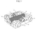
- Figure 1 is a perspective view showing a conventional ventilating system.
- the ventilating system includes a case 2 which is mounted on a wall for dividing indoor and outdoor, ventilating fans 4 and 6 which are mounted in the case 2, for ventilating air which is sucked and discharged, an air cleaner (not shown) which is installed in a portion to which the outdoor air inside the case 2 is sucked, for cleaning the outdoor air sucked to the indoor, and a heat exchanger 8 which is positioned inside the case 2, for performing a heat exchanging operation of indoor air discharged the outdoor and outdoor air sucked to the indoor.
- the case 2 is disposed in a hole formed on the wall for diving the indoor and outdoor, and accordingly, one side is positioned indoors and the other side is positioned outdoors.
- an outdoor suction hole 10 to which outdoor air is sucked and an indoor discharging hole 12 through which indoor air is discharged to the outdoor are respectively formed on the side wall of the case 2 positioned outdoors
- an indoor discharging hole 14 through which outdoor air is discharged to the indoor and indoor suction hole 16 to which indoor air is sucked to the outdoor are respectively formed on the side wall of the case 2 positioned indoors.
- the ventilating fans 4 and 6 includes a discharging blowing fan4 which is installed in a position connected with the outdoor discharging hole 12, for providing a blowing pressure for discharging the indoor air to the outdoor, and a suction blowing fan6 which is installed in a position connected with the indoor discharging hole 14, for providing a blowing pressure for sucking the outdoor air to the indoor.
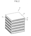
- Figure 2 is a perspective view showing a conventional heat exchanger of a ventilating system
- Figure 3 is a partial perspective view showing the conventional heat exchanger of a ventilating system.
- the conventional heat exchanger 8 includes a plurality of base plates 20 which are laminated at a regular interval in a shape of a thin plate, first corrugation plates 22 which are respectively laminated in the spaces among the base plates 20, through which indoor air passes, and second corrugation plates 24 which are respectively laminated in the base plates 20 to be mutually crossed with the first corrugation plates 22 in turn, through which outdoor air passes.
- first and second corrugation plates 22 and 24 are curved in a triangular shape, and indoor and outdoor air passes to the inner and outer sides thereof, thus to mutually exchange heat.
- Such heat exchanger 8 is formed in a rectangular shape by sequentially laminating the first corrugation plates 22, base plates 20, and second corrugation plates 24.
- the upper and lower surfaces of the heat exchanger 8 are respectively closed by the base plate 20, and the both side surfaces of the heat exchanger are connected with the outdoor suction hole 10 and indoor discharging hole 14, and outdoor air passes therethrough.
- Another both side surfaces of the heat exchanger are respectively connected with the outdoor discharging hole 12 and indoor suction hole 16, and indoor air passes therethrough.
- the outdoor air is sucked to the outdoor suction port 10 and is supplied to the indoor through the indoor discharging hole 14 by passing the first corrugation plate 22.
- the discharging blowing fan4 is driven, the indoor air is sucked through the indoor suction hole 16 and discharged to the indoor through the outdoor discharging hole 12 by passing the second corrugation plate 24.
- the first and second corrugation plates 22 and 24 are formed in a shape of a plate having a corrugation of a predetermined shape, and a boundary layer S is developed as the air flowing in the first and second corrugation plates moves along from the inlet side to the outlet side. Therefore, heat transfer efficiency is degraded and indoor temperature is rapidly changed in case of ventilating since the outdoor air sucked to the indoor could not absorb heat in the indoor air. Also, energy consumption for recovering the indoor air is increased and indoor air conditioning performance is degraded.
- the boundary layer is developed and the air is air gets apart from the surface of the inside of the pipe, thus to degrade heat transfer efficiency that the heat of the indoor air is transferred to the outdoor air through the base plate 20.
- JP 54014049 discloses a heat exchanger comprising fins, the fins being provided with a vibrating element which vibrates and causes turbulence of air as the air passes through the fins.
- FR2804471 which discloses the features of the preamble of claim 1, describes an air cooler comprising a block of flat tubes between which are disposed fins in the form of corrugated ribs, and within which flat tubes are internal fins including vortex generators.
- the vortex generators may be formed by stamping out and bending tongues from a surface of an element forming the internal fins.
- an object of the present invention is to provide a heat exchanger of a ventilating system, capable of improving heat transfer performance by restraining development of the boundary layer by increasing - turbulence of outdoor and indoor air passing through the heat exchanger.
- a heat exchanger of a ventilating system the heat exchanger being as defined in claim 1.
- the heat exchanger of the ventilating system may include a first partition which is respectively attached on the both side surfaces of the heat exchanger through which the outdoor air passes, for closing the side surface where the second vibration member is aligned and a second partition which is attached on the other both side surfaces of the heat exchanger through which the indoorair passes, for closing the side surface where the first vibration member is aligned.
- the first and second vibration members may be formed with an elastic body having a predetermined elasticity that the vibration portion is bent to the rear direction when the air is collided with a front surface thereof.
- the first and second vibration members may be formed with metal materials having a predetermined elasticity.
- the first and second vibration members may be formed with paper materials having a predetermined elasticity.
- the first and second vibration members may be formed with plastic materials having a predetermined elasticity.
- the interval among the vibration members of the first row portions and second row portions is d1 and the interval among the vibration members of the first row portions and second row portions is d2, and the formula of 5 ⁇ d 2/ d 1 ⁇ 10 may be satisfied.
- the width of the vibration members of the first row portions and second row portions is L1 and the width of the vibration members of the first row portions and second row portions is L2, the formula of 1 ⁇ L 1/ L 2 ⁇ 5 may be satisfied.
- the thickness of the vibration members of the first row portions and second row portions is t1 and the thickness of the heat exchange plates is t2
- the thickness of the first row portions and second row portions and the thickness of the heat exchange plates may satisfy a formula of 0.5 ⁇ t 2/ t 1 ⁇ 1.
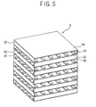
- FIG. 5 is a perspective view showing a heat exchanger of a ventilating system in accordance with the present invention.
- a case 2 is mounted to penetrate a wall which divides the indoor and outdoor, a side surface of the case 2 is positioned outdoors and the other side surface is positioned indoors.
- an outdoor suction hole 10 through which the outdoor air is sucked and an outdoor discharging hole 12 through which the indoor air is discharged are respectively formed on a side surface positioned at the outdoor of the case 2, and an indoor discharging hole 14 through which the outdoor air is discharged to the indoor and an indoor suction hole 16 through which the indoor air is sucked are respectively connected on a side surface positioned at the indoor of the case 2.
- a discharging blowing fan 4 for giving a blowing pressure for discharging the indoor air to the outdoor is installed in a position connected with the outdoor discharging hole 12 inside the case 2
- a suction blowing fan 6 for giving a blowing pressure for sucking the outdoor air to the indoor is installed in a position connected with the indoor discharging hole 14 inside the case 2.
- An air cleaner (not shown) for removing foreign materials, dust and the like contained in the outdoor air is installed on the suction channel inside the case 2, and a heat exchanger 8 for transferring heat of the discharged indoor air to the sucked indoor air is installed inside the case 2.
- the heat exchanger 8 includes heat exchange plates 50 which are laminated in a thin plate shape at a predetermined interval, first vibration members 54 which are attached among the heat exchange plates 50, for generating turbulence in outdoor air passing through a first air path 52, being aligned in the first air path 52 through which outdoor air passes as plural, and second vibration members 58 for generating turbulence in the indoor air passing through a second air path 56, being aligned in the second air path 56 through which indoor air passes, as plural.
- a first partition 60 for closing the second air path 56 is attached on the both side surfaces of the heat exchanger 8 through which the outdoor air passes, and a second partition 62 for closing the second air path 56 is attached on the other both side surfaces of the heat exchanger 8 through which the indoor air passes.
- the first vibration member 54 and second vibration member 58 are attached in the direction that air passes, and is laminated in turn to be at right angles to each other to generate turbulence in the air.
- the vibration members are formed in a shape of a thin plate which is composed of a fixing portion 66 which is attached on the upper surface of the heat exchange plate 50, and a vibration portion which is curved at a predetermined angle from the fixing portion 66, for generating turbulence in the flowing air.
- the fixing portion 66 is attached by using an adhesive on the upper surface of the heat exchange plate 50, and the method can be any method that can attach the fixing portion 66 on the upper surface of the heat exchange plate 50.
- Such vibration members 54 and 58 are formed as an elastic body having a predetermined elasticity that the vibration portion 68 is bent to the rear direction when air is collided with the front surface thereof, and more definitely, it is desirable that the members are formed with thin aluminum materials or paper materials.
- vibration members 54 and 58 can be manufactured with plastic materials such as the polyethylene or polypropylene.
- the vibration members 54 and 58 include first row portions 70 which are aligned at a predetermined interval on the upper surface of the heat exchange plate 50, and second row portion 72 which are aligned at a predetermined interval from the first row portion 70 at the rear of the first row portion 70, and the vibration members are composed by repeating a predetermined number of the second row portion 72 repeatedly aligned in spaces among the first row portions.
- the interval d1 among the vibration members of the first row portions 70 and second row portions 72 and the interval d2 among the vibration members of the first row portions 70 and second row portions 72 are aligned so that they satisfy the formula of 5 ⁇ d 2/ d 1 ⁇ 10.
- the width L2 and length L1 of the vibration members satisfy the formula of 1 ⁇ L 1/ L 2 ⁇ 5.
- the thickness t1 of the vibration members and the thickness t2 of the heat exchange plates satisfy the formula of 0.5 ⁇ t 2/ t 1 ⁇ 1.
- Figure 7 is a view showing operational status of the air passing through the heat exchanger in accordance with the embodiment of the present invention.
- the outdoor air is sucked through the outdoor suction hole 10 and various dusts and foreign materials are removed passing through the air cleaner, and the air is supplied to the indoor by passing the first air path 52 through the indoor discharging hole 14.
- the discharging blowing fan 4 is driven, the indoor air is sucked through the indoor suction hole 16, and is discharged into the outdoor by passing the second air path through the outdoor discharging hole 12.
- the outdoor air is collided with the surfaces of the first vibration members 58 and dispersed in all directions. Therefore, heat transfer performance to the heat exchange plate 50 can be improved as the air flows in contact with the surface of the heat exchange plate 50.
- the indoor air flowed to the second air path 56 is dispersed in all directions, while being collided with the surface of the second vibration member 58 and flows in contact with on the surface of the heat exchange plate 50, thus to improve heat transfer performance to the heat exchange plate 50.
- turbulence of the outdoor and indoor air can be increased by the operation of the first and second vibration members by attaching the first vibration member on the first air path through which the outdoor air passes and the second vibration member in the second air path through which the indoor air passes, and accordingly, the heat transfer performance can be improved by restraining development of a boundary layer.
- the indoor temperature can be uniformly maintained. Accordingly, the indoor environment can be made to be comfortable, and energy consumption can be reduced by minimizing the change of the indoor temperature.
Landscapes
- Engineering & Computer Science (AREA)
- Mechanical Engineering (AREA)
- General Engineering & Computer Science (AREA)
- Physics & Mathematics (AREA)
- Thermal Sciences (AREA)
- Chemical & Material Sciences (AREA)
- Combustion & Propulsion (AREA)
- Heat-Exchange Devices With Radiators And Conduit Assemblies (AREA)
Claims (9)
- Wärmetauscher (8) eines Lüftungssystems, umfassend:Wärmetauscherplatten (50), die in einem vorbestimmten Intervall geschichtet sind;erste Schwingungsglieder (54), die sich zwischen den Wärmetauscherplatten (50) befinden, zur Erzeugung von Turbulenz in durch einen ersten Luftweg (52) strömender Außenluft, die in dem ersten von der Außenluft durchströmten Luftweg (52) ausgerichtet sind; undzweite Schwingungsglieder (58) zur Erzeugung von Turbulenz in durch einen zweiten Luftweg (56) strömender Innenluft, die in dem zweiten von der Innenluft durchströmten Luftweg (56) ausgerichtet sind,wobei jedes der ersten und zweiten Schwingungsglieder (54, 58) einen in einem vorbestimmten Winkel gebogenen Schwingungsabschnitt (68) zur Erzeugung von Turbulenz in der Strömungsluft umfasst,wobei jedes der ersten und zweiten Schwingungsglieder (54, 58) erste Reihenabschnitte (70) und zweite Reihenabschnitte (72) umfasst, undwobei die ersten Reihenabschnitte (70) auf der Oberfläche der Wärmetauscherplatte (50) in einem vorbestimmten Intervall ausgerichtet sind, die zweiten Reihenschwingungsabschnitte (72) hinter den ersten Reihenabschnitten (70) in einem vorbestimmten Intervall von den ersten Reihenabschnitten (70) ausgerichtet sind, die ersten und zweiten Schwingungsglieder wiederholt bei einem identischen Intervall ausgerichtet sind und die zweiten Reihenabschnitte (72) zwischen den ersten Reihenabschnitten (70) positioniert sind;dadurch gekennzeichnet, dass die ersten Schwingungsglieder (54) zwischen die Wärmetauscherplatten (50) geschichtet sind;dass jedes der ersten und zweiten Schwingungsglieder (54, 58) einen Befestigungsabschnitt (66), der an der Oberfläche der Wärmetauscherplatte (50) befestigt ist, umfasst; unddass der Schwingungsabschnitt (68) in einem vorbestimmten Winkel von dem Befestigungsabschnitt (66) gebogen ist.
- Tauscher (8) nach Anspruch 1, ferner umfassend:eine erste Scheidewand (60), die jeweils an den beiden Seitenflächen des Wärmetauschers (8), durch die die Außenluft strömt, befestigt ist, zum Schließen der Seitenfläche, wo die zweiten Schwingungsglieder (58) ausgerichtet sind, undzweite Scheidewände (62), die jeweils an den beiden anderen Seitenflächen des Wärmetauschers (8), durch die die Innenluft strömt, befestigt sind, zum Schließen der Seitenfläche, wo die ersten Schwingungsglieder (54) ausgerichtet sind.
- Tauscher (8) nach Anspruch 1, wobei die ersten und zweiten Schwingungsglieder (54, 58) aus einem elastischen Körper mit einer vorbestimmten Elastizität gebildet sind, wobei der Schwingungsabschnitt (68) nach hinten gebogen wird, wenn die Luft auf dessen Vorderfläche auftrifft.
- Tauscher (8) nach Anspruch 1, wobei die ersten und zweiten Schwingungsglieder (54, 58) aus Metallmaterialen mit einer vorbestimmten Elastizität gebildet sind.
- Tauscher (8) nach Anspruch 1, wobei die ersten und zweiten Schwingungsglieder (54, 58) aus Papiermaterialien mit einer vorbestimmten Elastizität gebildet sind.
- Tauscher (8) nach Anspruch 1, wobei die ersten und zweiten Schwingungsglieder (54, 58) aus Kunststoffmaterialien mit einer vorbestimmten Elastizität gebildet sind.
- Tauscher nach Anspruch 1, wobei, wenn das Intervall zwischen den Schwingungsgliedern der ersten Reihenabschnitte (70) und zweiten Reihenabschnitte (72) d1 ist und das Intervall zwischen den Schwingungsgliedern der ersten Reihenabschnitte (70) und zweiten Reihenabschnitte (72) d2 ist, die Formel 5 δ d2/d1 δ 10 erfüllt ist.
- Tauscher nach Anspruch 1, wobei, wenn die Breite der Schwingungsglieder der ersten Reihenabschnitte (70) und zweiten Reihenabschnitte (72) L1 ist und die Breite der Schwingungsglieder der ersten Reihenabschnitte (70) und zweiten Reihenabschnitte (72) L2 ist, die Formel 1 δ L1/L2 δ 5 erfüllt ist.
- Tauscher nach Anspruch 1, wobei, wenn die Dicke der Schwingungsglieder der ersten Reihenabschnitte (70) und zweiten Reihenabschnitte (72) t1 ist und die Dicke der Wärmetauscherplatten (50) t2 ist, die Dicke der ersten Reihenabschnitte (70) und zweiten Reihenabschnitte (72) und die Dicke der Wärmetauscherplatten (50) die Formel 0,5 δ t2/t1 δ 1 erfüllen.
Applications Claiming Priority (1)
| Application Number | Priority Date | Filing Date | Title |
|---|---|---|---|
| PCT/KR2002/002266 WO2004051173A2 (en) | 2002-12-02 | 2002-12-02 | Heat exchanger of ventilating system |
Publications (2)
| Publication Number | Publication Date |
|---|---|
| EP1570221A2 EP1570221A2 (de) | 2005-09-07 |
| EP1570221B1 true EP1570221B1 (de) | 2012-05-23 |
Family
ID=32464305
Family Applications (1)
| Application Number | Title | Priority Date | Filing Date |
|---|---|---|---|
| EP02791013A Expired - Lifetime EP1570221B1 (de) | 2002-12-02 | 2002-12-02 | Wärmetauscher einer lüftungsanlage |
Country Status (6)
| Country | Link |
|---|---|
| US (1) | US7147049B2 (de) |
| EP (1) | EP1570221B1 (de) |
| CN (1) | CN100449246C (de) |
| AU (1) | AU2002368424B2 (de) |
| ES (1) | ES2388329T3 (de) |
| WO (1) | WO2004051173A2 (de) |
Families Citing this family (10)
| Publication number | Priority date | Publication date | Assignee | Title |
|---|---|---|---|---|
| US20090223648A1 (en) * | 2008-03-07 | 2009-09-10 | James Scott Martin | Heat exchanger with variable heat transfer properties |
| US8783046B2 (en) * | 2009-12-08 | 2014-07-22 | Wet Enterprises, Inc. | Ice display device |
| US8640455B2 (en) * | 2010-06-02 | 2014-02-04 | GM Global Technology Operations LLC | Controlling heat in a system using smart materials |
| US9140502B2 (en) * | 2010-07-08 | 2015-09-22 | Hamilton Sundstrand Corporation | Active structures for heat exchanger |
| US20130194751A1 (en) * | 2012-01-30 | 2013-08-01 | Wei Ling | Controlling heat transfer using airflow-induced flutter of cantilevered elastic plates |
| KR101440723B1 (ko) * | 2013-03-14 | 2014-09-17 | 정인숙 | 현열교환기, 이를 포함하는 열회수 환기장치, 및 그 해빙운전과 점검운전 방법 |
| NL2015996B1 (en) * | 2015-12-21 | 2017-06-30 | Recair Holding B V | Heat exchanger. |
| CN106705715B (zh) * | 2017-01-20 | 2018-09-28 | 陕西智拓固相增材制造技术有限公司 | 换热器 |
| WO2020101628A1 (en) * | 2018-11-14 | 2020-05-22 | Anadolu Universitesi | Heat exchanger with movable blades |
| US11039550B1 (en) * | 2020-04-08 | 2021-06-15 | Google Llc | Heat sink with turbulent structures |
Family Cites Families (12)
| Publication number | Priority date | Publication date | Assignee | Title |
|---|---|---|---|---|
| US2359288A (en) * | 1942-07-20 | 1944-10-03 | Young Radiator Co | Turbulence strip for heat exchangers |
| US2691991A (en) * | 1950-08-30 | 1954-10-19 | Gen Motors Corp | Heat exchange device |
| SU556311A1 (ru) | 1970-11-02 | 1977-04-30 | Одесский Технологический Институт Холодильной Промышленности | Насадка тепломассообменного аппарата |
| FR2123195B1 (de) * | 1971-01-28 | 1973-12-07 | Chausson Usines Sa | |
| JPS5414049B2 (de) | 1973-01-12 | 1979-06-04 | ||
| CN86108632A (zh) * | 1986-12-15 | 1987-07-29 | 黄一明 | 塑料凹凸型折叠式换热器 |
| US4899812A (en) * | 1988-09-06 | 1990-02-13 | Westinghouse Electric Corp. | Self-securing turbulence promoter to enhance heat transfer |
| JPH0882495A (ja) * | 1994-09-12 | 1996-03-26 | Matsushita Seiko Co Ltd | 熱交換器 |
| JPH10122787A (ja) | 1996-10-23 | 1998-05-15 | Honda Motor Co Ltd | ピンフィン型熱交換器 |
| JPH11132686A (ja) * | 1997-08-28 | 1999-05-21 | Chiyoda Container Corp | 熱交換型換気装置 |
| US6729388B2 (en) * | 2000-01-28 | 2004-05-04 | Behr Gmbh & Co. | Charge air cooler, especially for motor vehicles |
| DE10102088A1 (de) | 2000-01-28 | 2001-08-16 | Behr Gmbh & Co | Ladeluftkühler, insbesondere für Kraftfahrzeuge |
-
2002
- 2002-12-02 US US10/537,154 patent/US7147049B2/en not_active Expired - Fee Related
- 2002-12-02 EP EP02791013A patent/EP1570221B1/de not_active Expired - Lifetime
- 2002-12-02 AU AU2002368424A patent/AU2002368424B2/en not_active Ceased
- 2002-12-02 WO PCT/KR2002/002266 patent/WO2004051173A2/en not_active Ceased
- 2002-12-02 CN CNB028301811A patent/CN100449246C/zh not_active Expired - Fee Related
- 2002-12-02 ES ES02791013T patent/ES2388329T3/es not_active Expired - Lifetime
Also Published As
| Publication number | Publication date |
|---|---|
| AU2002368424B2 (en) | 2007-09-06 |
| AU2002368424A1 (en) | 2004-06-23 |
| EP1570221A2 (de) | 2005-09-07 |
| WO2004051173A2 (en) | 2004-06-17 |
| US7147049B2 (en) | 2006-12-12 |
| ES2388329T3 (es) | 2012-10-11 |
| CN1735784A (zh) | 2006-02-15 |
| CN100449246C (zh) | 2009-01-07 |
| US20060054309A1 (en) | 2006-03-16 |
| WO2004051173A3 (en) | 2005-03-10 |
Similar Documents
| Publication | Publication Date | Title |
|---|---|---|
| US7228891B2 (en) | Heat exchanger of ventilating system | |
| US7147049B2 (en) | Heat exchanger of ventilating system | |
| EP1573262B1 (de) | Wärmetauscher einer lüftungsanlage | |
| EP1570220B1 (de) | Wärmetauscher einer lüftungsanlage | |
| EP1680638B1 (de) | Wärmetauscher für ventilator | |
| EP1704377B1 (de) | Wärmetauscher für ventilator | |
| CN101398239A (zh) | 热交换器以及具备该热交换器的空气调节器 | |
| KR100664281B1 (ko) | 환기 장치용 열교환기 | |
| KR100898926B1 (ko) | 환기 장치용 열교환기 | |
| JP2008275298A (ja) | 空気熱交換ユニット及び熱交換モジュール | |
| KR20050086741A (ko) | 환기 장치용 열교환기 | |
| KR20050089801A (ko) | 환기 장치용 열교환기 | |
| JP2005164074A (ja) | 空気調和装置 | |
| KR20040040161A (ko) | 공기조화기용 열교환소자 조립체 |
Legal Events
| Date | Code | Title | Description |
|---|---|---|---|
| PUAI | Public reference made under article 153(3) epc to a published international application that has entered the european phase |
Free format text: ORIGINAL CODE: 0009012 |
|
| 17P | Request for examination filed |
Effective date: 20050609 |
|
| AK | Designated contracting states |
Kind code of ref document: A2 Designated state(s): AT BE BG CH CY CZ DE DK EE ES FI FR GB GR IE IT LI LU MC NL PT SE SI SK TR |
|
| AX | Request for extension of the european patent |
Extension state: AL LT LV MK RO |
|
| DAX | Request for extension of the european patent (deleted) | ||
| 17Q | First examination report despatched |
Effective date: 20070927 |
|
| REG | Reference to a national code |
Ref country code: DE Ref legal event code: R079 Ref document number: 60242984 Country of ref document: DE Free format text: PREVIOUS MAIN CLASS: F28F0001000000 Ipc: F24F0012000000 |
|
| GRAP | Despatch of communication of intention to grant a patent |
Free format text: ORIGINAL CODE: EPIDOSNIGR1 |
|
| RIC1 | Information provided on ipc code assigned before grant |
Ipc: F28D 9/00 20060101ALI20111107BHEP Ipc: F24F 12/00 20060101AFI20111107BHEP Ipc: F28F 13/12 20060101ALI20111107BHEP |
|
| RIN1 | Information on inventor provided before grant (corrected) |
Inventor name: SHIN, SOO-YEONBOOYOUNG APT. Inventor name: CHO, MIN-CHUL Inventor name: LEE, SEONG-HWAN Inventor name: LEE, SUNG-HWA |
|
| RAP1 | Party data changed (applicant data changed or rights of an application transferred) |
Owner name: LG ELECTRONICS INC. |
|
| GRAS | Grant fee paid |
Free format text: ORIGINAL CODE: EPIDOSNIGR3 |
|
| GRAA | (expected) grant |
Free format text: ORIGINAL CODE: 0009210 |
|
| AK | Designated contracting states |
Kind code of ref document: B1 Designated state(s): AT BE BG CH CY CZ DE DK EE ES FI FR GB GR IE IT LI LU MC NL PT SE SI SK TR |
|
| REG | Reference to a national code |
Ref country code: GB Ref legal event code: FG4D |
|
| REG | Reference to a national code |
Ref country code: CH Ref legal event code: EP |
|
| REG | Reference to a national code |
Ref country code: AT Ref legal event code: REF Ref document number: 559271 Country of ref document: AT Kind code of ref document: T Effective date: 20120615 |
|
| REG | Reference to a national code |
Ref country code: IE Ref legal event code: FG4D |
|
| REG | Reference to a national code |
Ref country code: DE Ref legal event code: R096 Ref document number: 60242984 Country of ref document: DE Effective date: 20120719 |
|
| REG | Reference to a national code |
Ref country code: NL Ref legal event code: VDEP Effective date: 20120523 |
|
| REG | Reference to a national code |
Ref country code: ES Ref legal event code: FG2A Ref document number: 2388329 Country of ref document: ES Kind code of ref document: T3 Effective date: 20121011 |
|
| PG25 | Lapsed in a contracting state [announced via postgrant information from national office to epo] |
Ref country code: SE Free format text: LAPSE BECAUSE OF FAILURE TO SUBMIT A TRANSLATION OF THE DESCRIPTION OR TO PAY THE FEE WITHIN THE PRESCRIBED TIME-LIMIT Effective date: 20120523 Ref country code: CY Free format text: LAPSE BECAUSE OF FAILURE TO SUBMIT A TRANSLATION OF THE DESCRIPTION OR TO PAY THE FEE WITHIN THE PRESCRIBED TIME-LIMIT Effective date: 20120523 Ref country code: FI Free format text: LAPSE BECAUSE OF FAILURE TO SUBMIT A TRANSLATION OF THE DESCRIPTION OR TO PAY THE FEE WITHIN THE PRESCRIBED TIME-LIMIT Effective date: 20120523 |
|
| REG | Reference to a national code |
Ref country code: AT Ref legal event code: MK05 Ref document number: 559271 Country of ref document: AT Kind code of ref document: T Effective date: 20120523 |
|
| PG25 | Lapsed in a contracting state [announced via postgrant information from national office to epo] |
Ref country code: SI Free format text: LAPSE BECAUSE OF FAILURE TO SUBMIT A TRANSLATION OF THE DESCRIPTION OR TO PAY THE FEE WITHIN THE PRESCRIBED TIME-LIMIT Effective date: 20120523 Ref country code: PT Free format text: LAPSE BECAUSE OF FAILURE TO SUBMIT A TRANSLATION OF THE DESCRIPTION OR TO PAY THE FEE WITHIN THE PRESCRIBED TIME-LIMIT Effective date: 20120924 Ref country code: GR Free format text: LAPSE BECAUSE OF FAILURE TO SUBMIT A TRANSLATION OF THE DESCRIPTION OR TO PAY THE FEE WITHIN THE PRESCRIBED TIME-LIMIT Effective date: 20120824 |
|
| PG25 | Lapsed in a contracting state [announced via postgrant information from national office to epo] |
Ref country code: BE Free format text: LAPSE BECAUSE OF FAILURE TO SUBMIT A TRANSLATION OF THE DESCRIPTION OR TO PAY THE FEE WITHIN THE PRESCRIBED TIME-LIMIT Effective date: 20120523 |
|
| PG25 | Lapsed in a contracting state [announced via postgrant information from national office to epo] |
Ref country code: NL Free format text: LAPSE BECAUSE OF FAILURE TO SUBMIT A TRANSLATION OF THE DESCRIPTION OR TO PAY THE FEE WITHIN THE PRESCRIBED TIME-LIMIT Effective date: 20120523 Ref country code: CZ Free format text: LAPSE BECAUSE OF FAILURE TO SUBMIT A TRANSLATION OF THE DESCRIPTION OR TO PAY THE FEE WITHIN THE PRESCRIBED TIME-LIMIT Effective date: 20120523 Ref country code: AT Free format text: LAPSE BECAUSE OF FAILURE TO SUBMIT A TRANSLATION OF THE DESCRIPTION OR TO PAY THE FEE WITHIN THE PRESCRIBED TIME-LIMIT Effective date: 20120523 Ref country code: DK Free format text: LAPSE BECAUSE OF FAILURE TO SUBMIT A TRANSLATION OF THE DESCRIPTION OR TO PAY THE FEE WITHIN THE PRESCRIBED TIME-LIMIT Effective date: 20120523 Ref country code: SK Free format text: LAPSE BECAUSE OF FAILURE TO SUBMIT A TRANSLATION OF THE DESCRIPTION OR TO PAY THE FEE WITHIN THE PRESCRIBED TIME-LIMIT Effective date: 20120523 Ref country code: EE Free format text: LAPSE BECAUSE OF FAILURE TO SUBMIT A TRANSLATION OF THE DESCRIPTION OR TO PAY THE FEE WITHIN THE PRESCRIBED TIME-LIMIT Effective date: 20120523 |
|
| PLBE | No opposition filed within time limit |
Free format text: ORIGINAL CODE: 0009261 |
|
| STAA | Information on the status of an ep patent application or granted ep patent |
Free format text: STATUS: NO OPPOSITION FILED WITHIN TIME LIMIT |
|
| 26N | No opposition filed |
Effective date: 20130226 |
|
| REG | Reference to a national code |
Ref country code: DE Ref legal event code: R097 Ref document number: 60242984 Country of ref document: DE Effective date: 20130226 |
|
| PG25 | Lapsed in a contracting state [announced via postgrant information from national office to epo] |
Ref country code: MC Free format text: LAPSE BECAUSE OF NON-PAYMENT OF DUE FEES Effective date: 20121231 Ref country code: BG Free format text: LAPSE BECAUSE OF FAILURE TO SUBMIT A TRANSLATION OF THE DESCRIPTION OR TO PAY THE FEE WITHIN THE PRESCRIBED TIME-LIMIT Effective date: 20120823 |
|
| REG | Reference to a national code |
Ref country code: CH Ref legal event code: PL |
|
| GBPC | Gb: european patent ceased through non-payment of renewal fee |
Effective date: 20121202 |
|
| REG | Reference to a national code |
Ref country code: IE Ref legal event code: MM4A |
|
| PG25 | Lapsed in a contracting state [announced via postgrant information from national office to epo] |
Ref country code: CH Free format text: LAPSE BECAUSE OF NON-PAYMENT OF DUE FEES Effective date: 20121231 Ref country code: IE Free format text: LAPSE BECAUSE OF NON-PAYMENT OF DUE FEES Effective date: 20121202 Ref country code: LI Free format text: LAPSE BECAUSE OF NON-PAYMENT OF DUE FEES Effective date: 20121231 |
|
| PG25 | Lapsed in a contracting state [announced via postgrant information from national office to epo] |
Ref country code: GB Free format text: LAPSE BECAUSE OF NON-PAYMENT OF DUE FEES Effective date: 20121202 |
|
| PG25 | Lapsed in a contracting state [announced via postgrant information from national office to epo] |
Ref country code: TR Free format text: LAPSE BECAUSE OF FAILURE TO SUBMIT A TRANSLATION OF THE DESCRIPTION OR TO PAY THE FEE WITHIN THE PRESCRIBED TIME-LIMIT Effective date: 20120523 |
|
| PG25 | Lapsed in a contracting state [announced via postgrant information from national office to epo] |
Ref country code: LU Free format text: LAPSE BECAUSE OF NON-PAYMENT OF DUE FEES Effective date: 20121202 |
|
| REG | Reference to a national code |
Ref country code: FR Ref legal event code: PLFP Year of fee payment: 14 |
|
| REG | Reference to a national code |
Ref country code: FR Ref legal event code: PLFP Year of fee payment: 15 |
|
| REG | Reference to a national code |
Ref country code: FR Ref legal event code: PLFP Year of fee payment: 16 |
|
| PGFP | Annual fee paid to national office [announced via postgrant information from national office to epo] |
Ref country code: FR Payment date: 20171110 Year of fee payment: 16 |
|
| PGFP | Annual fee paid to national office [announced via postgrant information from national office to epo] |
Ref country code: IT Payment date: 20171215 Year of fee payment: 16 |
|
| PGFP | Annual fee paid to national office [announced via postgrant information from national office to epo] |
Ref country code: ES Payment date: 20180116 Year of fee payment: 16 |
|
| PG25 | Lapsed in a contracting state [announced via postgrant information from national office to epo] |
Ref country code: IT Free format text: LAPSE BECAUSE OF NON-PAYMENT OF DUE FEES Effective date: 20181202 Ref country code: FR Free format text: LAPSE BECAUSE OF NON-PAYMENT OF DUE FEES Effective date: 20181231 |
|
| PGFP | Annual fee paid to national office [announced via postgrant information from national office to epo] |
Ref country code: DE Payment date: 20191105 Year of fee payment: 18 |
|
| REG | Reference to a national code |
Ref country code: ES Ref legal event code: FD2A Effective date: 20200131 |
|
| PG25 | Lapsed in a contracting state [announced via postgrant information from national office to epo] |
Ref country code: ES Free format text: LAPSE BECAUSE OF NON-PAYMENT OF DUE FEES Effective date: 20181203 |
|
| REG | Reference to a national code |
Ref country code: DE Ref legal event code: R119 Ref document number: 60242984 Country of ref document: DE |
|
| PG25 | Lapsed in a contracting state [announced via postgrant information from national office to epo] |
Ref country code: DE Free format text: LAPSE BECAUSE OF NON-PAYMENT OF DUE FEES Effective date: 20210701 |