EP1570220B1 - Wärmetauscher einer lüftungsanlage - Google Patents
Wärmetauscher einer lüftungsanlage Download PDFInfo
- Publication number
- EP1570220B1 EP1570220B1 EP02791011A EP02791011A EP1570220B1 EP 1570220 B1 EP1570220 B1 EP 1570220B1 EP 02791011 A EP02791011 A EP 02791011A EP 02791011 A EP02791011 A EP 02791011A EP 1570220 B1 EP1570220 B1 EP 1570220B1
- Authority
- EP
- European Patent Office
- Prior art keywords
- heat exchange
- air
- heat exchanger
- indoor
- heat
- Prior art date
- Legal status (The legal status is an assumption and is not a legal conclusion. Google has not performed a legal analysis and makes no representation as to the accuracy of the status listed.)
- Expired - Lifetime
Links
- 238000005192 partition Methods 0.000 claims description 8
- 230000000452 restraining effect Effects 0.000 abstract description 2
- 238000007599 discharging Methods 0.000 description 21
- 238000004049 embossing Methods 0.000 description 11
- 238000007664 blowing Methods 0.000 description 8
- 239000000463 material Substances 0.000 description 4
- 239000000428 dust Substances 0.000 description 2
- 238000005265 energy consumption Methods 0.000 description 2
- 238000000034 method Methods 0.000 description 2
- 125000006850 spacer group Chemical group 0.000 description 2
- 238000009423 ventilation Methods 0.000 description 2
- 238000004378 air conditioning Methods 0.000 description 1
- 238000004140 cleaning Methods 0.000 description 1
- 230000009189 diving Effects 0.000 description 1
- 238000010030 laminating Methods 0.000 description 1
- 238000012986 modification Methods 0.000 description 1
- 230000004048 modification Effects 0.000 description 1
- 239000002245 particle Substances 0.000 description 1
- 230000000717 retained effect Effects 0.000 description 1
- 239000011343 solid material Substances 0.000 description 1
Images




Classifications
-
- F—MECHANICAL ENGINEERING; LIGHTING; HEATING; WEAPONS; BLASTING
- F28—HEAT EXCHANGE IN GENERAL
- F28D—HEAT-EXCHANGE APPARATUS, NOT PROVIDED FOR IN ANOTHER SUBCLASS, IN WHICH THE HEAT-EXCHANGE MEDIA DO NOT COME INTO DIRECT CONTACT
- F28D9/00—Heat-exchange apparatus having stationary plate-like or laminated conduit assemblies for both heat-exchange media, the media being in contact with different sides of a conduit wall
- F28D9/0062—Heat-exchange apparatus having stationary plate-like or laminated conduit assemblies for both heat-exchange media, the media being in contact with different sides of a conduit wall the conduits for one heat-exchange medium being formed by spaced plates with inserted elements
-
- F—MECHANICAL ENGINEERING; LIGHTING; HEATING; WEAPONS; BLASTING
- F28—HEAT EXCHANGE IN GENERAL
- F28D—HEAT-EXCHANGE APPARATUS, NOT PROVIDED FOR IN ANOTHER SUBCLASS, IN WHICH THE HEAT-EXCHANGE MEDIA DO NOT COME INTO DIRECT CONTACT
- F28D9/00—Heat-exchange apparatus having stationary plate-like or laminated conduit assemblies for both heat-exchange media, the media being in contact with different sides of a conduit wall
- F28D9/0031—Heat-exchange apparatus having stationary plate-like or laminated conduit assemblies for both heat-exchange media, the media being in contact with different sides of a conduit wall the conduits for one heat-exchange medium being formed by paired plates touching each other
- F28D9/0037—Heat-exchange apparatus having stationary plate-like or laminated conduit assemblies for both heat-exchange media, the media being in contact with different sides of a conduit wall the conduits for one heat-exchange medium being formed by paired plates touching each other the conduits for the other heat-exchange medium also being formed by paired plates touching each other
-
- F—MECHANICAL ENGINEERING; LIGHTING; HEATING; WEAPONS; BLASTING
- F28—HEAT EXCHANGE IN GENERAL
- F28F—DETAILS OF HEAT-EXCHANGE AND HEAT-TRANSFER APPARATUS, OF GENERAL APPLICATION
- F28F13/00—Arrangements for modifying heat-transfer, e.g. increasing, decreasing
- F28F13/02—Arrangements for modifying heat-transfer, e.g. increasing, decreasing by influencing fluid boundary
-
- F—MECHANICAL ENGINEERING; LIGHTING; HEATING; WEAPONS; BLASTING
- F28—HEAT EXCHANGE IN GENERAL
- F28F—DETAILS OF HEAT-EXCHANGE AND HEAT-TRANSFER APPARATUS, OF GENERAL APPLICATION
- F28F3/00—Plate-like or laminated elements; Assemblies of plate-like or laminated elements
- F28F3/02—Elements or assemblies thereof with means for increasing heat-transfer area, e.g. with fins, with recesses, with corrugations
- F28F3/025—Elements or assemblies thereof with means for increasing heat-transfer area, e.g. with fins, with recesses, with corrugations the means being corrugated, plate-like elements
-
- F—MECHANICAL ENGINEERING; LIGHTING; HEATING; WEAPONS; BLASTING
- F28—HEAT EXCHANGE IN GENERAL
- F28F—DETAILS OF HEAT-EXCHANGE AND HEAT-TRANSFER APPARATUS, OF GENERAL APPLICATION
- F28F3/00—Plate-like or laminated elements; Assemblies of plate-like or laminated elements
- F28F3/02—Elements or assemblies thereof with means for increasing heat-transfer area, e.g. with fins, with recesses, with corrugations
- F28F3/04—Elements or assemblies thereof with means for increasing heat-transfer area, e.g. with fins, with recesses, with corrugations the means being integral with the element
-
- Y—GENERAL TAGGING OF NEW TECHNOLOGICAL DEVELOPMENTS; GENERAL TAGGING OF CROSS-SECTIONAL TECHNOLOGIES SPANNING OVER SEVERAL SECTIONS OF THE IPC; TECHNICAL SUBJECTS COVERED BY FORMER USPC CROSS-REFERENCE ART COLLECTIONS [XRACs] AND DIGESTS
- Y02—TECHNOLOGIES OR APPLICATIONS FOR MITIGATION OR ADAPTATION AGAINST CLIMATE CHANGE
- Y02B—CLIMATE CHANGE MITIGATION TECHNOLOGIES RELATED TO BUILDINGS, e.g. HOUSING, HOUSE APPLIANCES OR RELATED END-USER APPLICATIONS
- Y02B30/00—Energy efficient heating, ventilation or air conditioning [HVAC]
- Y02B30/56—Heat recovery units
Definitions
- the present invention relates to a ventilating system for exchanging indoor air and outdoor air and particularly, to a heat exchanger of a ventilating system, capable of improving heat exchanging performance between outdoor air and indoor air.
- a ventilating system is a system for discharging polluted indoor air to the outdoor and sucking fresh outdoor air to the indoor, and the system includes an air cleaner for removing dust and foreign materials contained in the outdoor air, and a heat exchanger for transferring heat of the discharged indoor air to the sucked outdoor air.
- Figure 1 is a perspective view showing a conventional ventilating system.
- the ventilating system includes a case 2 which is mounted on a wall for dividing indoor and outdoor, blowing fans 4 and 6 which are mounted in the case 2, for ventilating air which is sucked and discharged, an air cleaner (not shown) which is installed in a portion to which the outdoor air inside the case 2 is sucked, for cleaning the outdoor air sucked to the indoor, and a heat exchanger 8 which is positioned inside the case 2, for performing a heat exchanging operation of indoor air discharged the outdoor and outdoor air sucked to the indoor.
- the case 2 is disposed in a hole formed on the wall for diving the indoor and outdoor, and accordingly, one side is positioned indoors and the other side is positioned outdoors.
- an outdoor suction hole 10 to which outdoor air is sucked and an indoor discharging hole 12 through which indoor air is discharged to the outdoor are respectively formed on the side wall of the case 2 positioned outdoors, and an indoor discharging hole 14 through which outdoor air is discharged to the indoor and indoor suction hole 16 to which indoor air is sucked are respectively formed on the side wall of the case 2 positioned indoors.
- the blowing fans 4 and 6 includes a discharging blowing fan 4 which is installed in a position connected with the outdoor discharging hole 12, for providing a blowing pressure for discharging the indoor air to the outdoor, and a suction blowing fan 6 which is installed in a position connected with the indoor discharging hole 14, for providing a blowing pressure for sucking the outdoor air to the indoor.
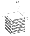
- Figure 2 is a perspective view showing a conventional heat exchanger of a ventilating system
- Figure 3 is a partial perspective view showing the conventional heat exchanger of a ventilating system.
- the conventional heat exchanger 8 includes a plurality of base plates 20 which are laminated at a regular interval in a shape of a thin plate, first corrugation plates 22 which are respectively laminated in the spaces among the base plates 20, through which indoor air passes, and second corrugation plates 24 which are respectively laminated in the base plates 20 to be mutually crossed with the first corrugation plates 22 in turn, through which outdoor air passes.
- first and second corrugation plates 22 and 24 are curved in a triangular shape, and indoor and outdoor air passes to the inner and outer sides thereof, thus to mutually exchange heat.
- Such heat exchanger 8 is formed in a rectangular shape by sequentially laminating the first corrugation plates 22, base plates 20, and second corrugation plates 24.
- the upper and lower surfaces of the heat exchanger 8 are respectively closed by the base plate 20, and the both side surfaces of the heat exchanger are connected with the outdoor suction hole 10 and indoor discharging hole 14, and outdoor air passes therethrough.
- Another both side surfaces of the heat exchanger are respectively connected with the outdoor discharging hole 12 and indoor suction hole 16, and indoor air passes therethrough.
- the outdoor air is sucked to the outdoor suction port 10 and is supplied to the indoor through the indoor discharging hole 14 by passing the first corrugation plate 22.
- the discharging blowing fan 4 is driven, the indoor air is sucked through the indoor suction hole 16 and discharged to the indoor through the outdoor discharging hole 12 by passing the second corrugation plate 24.
- the first and second corrugation plates 22 and 24 are formed in a shape of a plate having a corrugation of a predetermine a corrugation of a predetermineis developed as the air flowing in the first and second corrugation plates moves along from the inlet side to the outlet side. Therefore, heat transfer efficiency is degraded and indoor temperature is rapidly changed in case of ventilating since the outdoor air sucked to the indoor could not absorb heat in the indoor air. Also, energy consumption for recovering the indoor air is increased and indoor air conditioning performance is degraded.
- the boundary layer is developed and the air gets apart from the surface of the inside of the pipe, thus to degrade heat transfer efficiency that the heat of the indoor air is transferred to the outdoor air through the base plate 20.
- JP-A-59167696 discloses a heat exchanger in which primary and secondary air flows can freely flow through the same air flow paths and are mixed with each other in a mixing space which is formed of cut spacer sheets.
- US-A-4,460,388 discloses a heat exchanger comprising a spacer plate having a window or open portion therein.
- an object of the present invention is to provide a heat exchanger of a ventilating system, capable of improving heat transfer performance by restraining development of the boundary layer by improving air flowing structure of a heat exchanger.
- a heat exchanger of a ventilating system comprising: a plurality of heat exchange plates which are laminated at a predetermined interval, a first air path and a second air path being respectively located between adjacent heat exchange plates; a first heat exchange portion which is located in the first air path through which outdoor air passes; and a second heat exchange portion which is located in the second air path through which indoor air passes and crossed with the first heat exchanger portion, wherein each of the first and second heat exchange portions includes a plurality of heat exchange members having a predetermined length, and the heat exchange members are aligned at a predetermined interval (D1), characterized by a height (D2) of a path through which air of the heat exchange members (76) passes and the interval (D1) among the heat exchange members (76) being formed to satisfy a formula of 10 ⁇ D1 (in mm)/D2(in mm) ⁇ 15.
- First partitions for closing the second heat exchange portion are respectively attached on both side surfaces of the heat exchanger through which the outdoor air passes, and second partitions for closing the first heat exchange portion are respectively attached on the other both side surfaces of the heat exchanger through which the indoor air passes.
- Figures 6, 7 , 9 and 10 are not according to the presently claimed invention but have been retained in the present application for completeness.
- FIG. 5 is a perspective view showing a heat exchanger of a ventilating system in accordance with the present invention.
- a case 2 is mounted to penetrate a wall which divides the indoor and outdoor, a side surface of the case 2 is positioned indoors and the other side surface is positioned indoors.
- an outdoor suction hole 10 through which the outdoor air is sucked and an outdoor discharging hole 12 through which the indoor air is discharged are respectively formed on a side surface positioned at the outdoor of the case 2
- an indoor suction hole 14 through which the indoor air is sucked and an indoor discharging hole 16 through which the outdoor air is discharged are respectively formed on a side surface positioned at the indoor of the case 2.
- a discharging ventilating fan 4 for giving a ventilating pressure for discharging the indoor air to the outdoor is installed in a position connected with the outdoor discharging hole 12 inside the case 2
- a suction ventilating fan 6 for giving a ventilating pressure for sucking the outdoor air to the indoor is installed in a position connected with the indoor discharging hole 14 inside the case 2
- An air cleaner (not shown) for removing foreign materials, dust and the like contained in the outdoor air is installed on the suction channel inside the case 2, and a heat exchanger 8 for transferring heat of the discharged indoor air to the sucked indoor air is installed inside the case 2.
- the heat exchanger 8 includes heat exchange plates 50 which are laminated in a thin plate shape at a predetermined interval, a first heat exchange portion 52 which is laminated among the heat exchange plates 50 to have a space through which outdoor air passes and is aligned being divided as plural to prevent development of a boundary layer, and a second heat exchange portion 54 which is laminated among the heat exchange plates 50 to be right angles to the first heat exchange portion 52 to have a space through which indoor air passes and is aligned being divided as plural to prevent development of a boundary layer in case the indoor air flows.
- First partitions 62 for preventing inflow of indoor air to the first heat exchange portion 52 is attached on the both side surfaces of the heat exchanger through which the outdoor air passes
- second partition 64 for preventing inflow of outdoor air to the second heat exchange portion 54 is attached on the other both side surfaces of the heat exchanger through which the indoor air passes.
- the first and second heat exchange portions 52 and 54 are laminated at right angles to each other so that the outdoor air and indoor air flow at right angles to each other, but the portions have an identical shape.
- such first and second heat exchange portions 52 and 54 are composed of a plurality of heat exchange members 56 in which spaces through which air can pass by giving wave to the thin plate.
- the plurality of heat exchange members 56A and 56B are repeatedly aligned on the surface of the heat exchange plate 50 under the condition that the members are abutted to each other, and air passes on the inner and outer surfaces thereof.
- the heat exchange members 56A and 56B are aligned so that the air which passed through the inner surface 66 of one heat exchange member 56A passes the outer surface 72 of the heat exchange member 56B which is sequentially aligned. That is, the inner surface 66 of one heat exchange member 56A and outer surface 72 of the other heat exchange member 56B face each other.
- the length T of the heat exchange members 56A and 56B is manufactured as 3mm-6mm with which a boundary layer is not formed when the air flows.
- heat exchange members 56A and 56B of the first and second heat exchange portions 52 and 54 are manufactured with materials having an excellent heat transfer performance.
- the outdoor air is sucked to the outdoor suction hole 10, removes various dusts and foreign materials passing the air cleaner, and is supplied to the indoor through the indoor discharging hole 14 by passing the first heat exchange portion 52.
- the discharging ventilating fan 4 is driven, the indoor air is sucked to the indoor suction hole 16, and is discharged to the outdoor through the outdoor discharging hole 12 by passing the second the second heat exchange portion 54.
- the indoor air passing through the first heat exchange portion 52 and outdoor air passing through the second heat exchange portion 54 flow at right angles to each other, heat contained in the indoor air is sucked to the outdoor air through the heat exchange plate 50, and the completely heat exchanged outdoor air is supplied to the indoor.
- the air which passes the inner surface 66 of one heat exchange member 56A passes the outer surface of the other heat exchange member 56B right before a boundary layer which is parted from the surface of the heat exchange member 56A is formed, and accordingly, the air flows under the condition that the air is abutted on the surface of the other heat exchange member 56B as the condition becomes identical as in case the air initially passes the inside of the pipe as shown in an arrow P.
- the air which passes the outer surface 68 of one heat exchange member 56B passes the inner surface 70 of a heat exchange member 56A right before a boundary layer is formed, and accordingly, the air can continuously flow under the condition that the air is abutted on the surface of the heat exchange members 56A and 56B when the air passes the first and second heat exchange portions 52 and 54, thus to restrain development of the boundary later and improve performance of heat transfer performance.
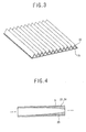
- FIG. 8 is a partial perspective view showing the heat exchange member of the heat exchanger of the ventilating system in accordance with an embodiment of the present invention.
- the heat exchanger in accordance with this embodiment is composed of said heat exchange plate 50, and first and second heat exchange portions 72 and 74 as in the first embodiment, but the structure that the heat exchange member is aligned in the heat exchange plate 50 is differentiated to restrain development of the boundary layer.
- a plurality of heat exchange members 76 are aligned at a predetermined interval as plural-In the heat exchange members 76, waves having a predetermined height are repeatedly formed so that air can pass on a thin plate having a predetermined length, and the heat exchange members 76 are formed at a predetermined interval D1.
- the height D2 of the triangular path of the heat exchange members 76 and the interval D1 among the heat exchange members 76 satisfy the formula of 10 ⁇ D1 (in mm) / D2 (in mm) ⁇ 15 to restrain development of the boundary layer.
- air respectively flows to the inner surface and outer surface of the heat exchange member 76, is mixed in a space among the heat exchange members, and flows to the inner and outer surfaces of the other heat exchange member 76. Since the process is repeated, development of the boundary layer is restrained, thus to improve heat exchange performance of the outdoor and indoor air.
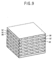
- FIG. 9 is a partial perspective view showing the heat exchanger of the ventilating system in accordance with another arrangement not in accordance with the present invention.
- a first air path 86 through which the outdoor air passes is formed by attaching a plurality of embossing protrusions 82 having a predetermined height among the heat exchange plates 80
- a second air path 88 through which the indoor air passes is formed by attaching a plurality of embossing protrusions 82 having a predetermined height in turn with the first air path 86 among the heat exchange plates 80.
- First partitions 90 for closing the second air path 88 is attached on the both side surfaces of the heat exchanger which is opened by the first air path 86
- second partition 92 for closing the first air path 86 is attached on the other both side surfaces of the heat exchanger which is opened by the second air path 88.
- embossing protrusions 82 embossing protrusions of the first row 82A are aligned on the upper surface of the heat exchange plate 80 at a predetermined interval, embossing protrusions of the second row 82B are respectively aligned among the embossing protrusions of the first row 82A, embossing protrusions of the third row 82C are respectively aligned among the embossing protrusions of the second row 82B. The above process is repeated.
- the first and second heat exchange portions in which the outdoor and indoor air respectively pass being at right angles to each other are attached being divided into a plurality of parts on the surface of the heat exchange plate. Accordingly, the divided heat exchange plates are positioned being crossed or positioned at a predetermined interval, development of the boundary layer in the air which passes therethrough, thus to improve heat transfer performance.
Landscapes
- Engineering & Computer Science (AREA)
- Physics & Mathematics (AREA)
- Thermal Sciences (AREA)
- Mechanical Engineering (AREA)
- General Engineering & Computer Science (AREA)
- Heat-Exchange Devices With Radiators And Conduit Assemblies (AREA)
- Central Air Conditioning (AREA)
- Devices For Blowing Cold Air, Devices For Blowing Warm Air, And Means For Preventing Water Condensation In Air Conditioning Units (AREA)
- Sorption Type Refrigeration Machines (AREA)
Claims (2)
- Wärmetauscher (8) einer Lüftungsanlage, umfassend:mehrere Wärmetauschplatten (50), die in einem vorbestimmten Abstand geschichtet sind, wobei ein erster Luftweg und ein zweiter Luftweg jeweils zwischen benachbarten Wärmetauschplatten liegen;ein erstes Wärmetauschteil (52), das in dem ersten Luftweg angeordnet ist, durch den Aussenluft gelangt; undein zweites Wärmetauschteil (54), das in dem zweiten Luftweg angeordnet ist, durch den Innenluft gelangt und das den ersten Wärmetauschteil kreuzend, liegt,wobei jedes erste und zweite Wärmetauschteil (52; 54) mehrere Wärmetauschelemente (76) aufweist, die eine vorbestimmte Länge haben und die Wärmetauschelemente in einem vorbestimmten Abstand (D1) ausgerichtet sind,
gekennezeichnet durch eine Höhe (D2) eines Weges, durch den Luft der Wärmetauschelemente (76) gelangt und dass der Abstand (D1) unter den Wärmetauschelementen (76) so gebildet ist, dass einer Formel 10 ≤ D1 (in mm)/D2 (in mm) ≤ 15, genügt ist. - Wärmetauscher nach Anspruch 1, bei dem erste Trennwände zum Abschließen des zweiten Wärmetauschteils (54) an beiden Seitenflächen des Wärmetauschers (8) angebracht sind, durch den die Aussenluft gelangt, und zweite Trennwände zum Abschließen des ersten Wärmetauschteils (52) an den anderen beiden Seitenflächen des Wärmetauschers angebracht sind, durch den die Innenluft gelangt.
Applications Claiming Priority (1)
| Application Number | Priority Date | Filing Date | Title |
|---|---|---|---|
| PCT/KR2002/002264 WO2004051171A2 (en) | 2002-12-02 | 2002-12-02 | Heat exchanger of ventilating system |
Publications (3)
| Publication Number | Publication Date |
|---|---|
| EP1570220A2 EP1570220A2 (de) | 2005-09-07 |
| EP1570220A3 EP1570220A3 (de) | 2005-10-26 |
| EP1570220B1 true EP1570220B1 (de) | 2008-03-19 |
Family
ID=32464303
Family Applications (1)
| Application Number | Title | Priority Date | Filing Date |
|---|---|---|---|
| EP02791011A Expired - Lifetime EP1570220B1 (de) | 2002-12-02 | 2002-12-02 | Wärmetauscher einer lüftungsanlage |
Country Status (8)
| Country | Link |
|---|---|
| US (1) | US7237603B2 (de) |
| EP (1) | EP1570220B1 (de) |
| CN (1) | CN100449249C (de) |
| AT (1) | ATE389858T1 (de) |
| AU (1) | AU2002368422B2 (de) |
| DE (1) | DE60225733T2 (de) |
| ES (1) | ES2302861T3 (de) |
| WO (1) | WO2004051171A2 (de) |
Cited By (1)
| Publication number | Priority date | Publication date | Assignee | Title |
|---|---|---|---|---|
| DE102014007735A1 (de) | 2013-05-29 | 2014-12-04 | Samuel Wepf | Lüftungsanlage |
Families Citing this family (3)
| Publication number | Priority date | Publication date | Assignee | Title |
|---|---|---|---|---|
| ES2315057B1 (es) * | 2005-08-31 | 2009-11-11 | Valeo Termico, S.A. | Intercambiador de calor de placas apiladas. |
| US20150144309A1 (en) * | 2013-03-13 | 2015-05-28 | Brayton Energy, Llc | Flattened Envelope Heat Exchanger |
| KR101440723B1 (ko) * | 2013-03-14 | 2014-09-17 | 정인숙 | 현열교환기, 이를 포함하는 열회수 환기장치, 및 그 해빙운전과 점검운전 방법 |
Family Cites Families (30)
| Publication number | Priority date | Publication date | Assignee | Title |
|---|---|---|---|---|
| US1833166A (en) * | 1928-09-13 | 1931-11-24 | Babcock & Wilcox Co | Heat exchanger |
| US2571631A (en) * | 1947-02-26 | 1951-10-16 | Kellogg M W Co | Heat exchange element |
| US2511084A (en) * | 1947-11-07 | 1950-06-13 | Young Radiator Co | Heat-exchanger core |
| US2985433A (en) * | 1957-01-22 | 1961-05-23 | Modine Mfg Co | Heat exchanger |
| US2959400A (en) * | 1957-11-27 | 1960-11-08 | Modine Mfg Co | Prime surface heat exchanger with dimpled sheets |
| US3568461A (en) * | 1967-11-22 | 1971-03-09 | Mc Donnell Douglas Corp | Fractionation apparatus |
| US3845814A (en) * | 1972-07-10 | 1974-11-05 | Union Carbide Corp | Finned primary surface heat exchanger |
| US4310960A (en) * | 1973-04-16 | 1982-01-19 | The Garrett Corporation | Method of fabrication of a formed plate, counterflow fluid heat exchanger and apparatus thereof |
| CH610648A5 (en) | 1976-09-21 | 1979-04-30 | Sulzer Ag | Heat exchanger, in particular for ventilating equipment |
| GB1601952A (en) * | 1977-02-17 | 1981-11-04 | Covrad Ltd | Apparatus for making corrugated sheet material |
| US4246963A (en) * | 1978-10-26 | 1981-01-27 | The Garrett Corporation | Heat exchanger |
| US4352273A (en) * | 1979-05-22 | 1982-10-05 | The Garrett Corporation | Fluid conditioning apparatus and system |
| US4460388A (en) * | 1981-07-17 | 1984-07-17 | Nippon Soken, Inc. | Total heat exchanger |
| DE3220774C2 (de) * | 1982-06-02 | 1986-09-25 | W. Schmidt GmbH & Co KG, 7518 Bretten | Plattenverdampfer oder -kondensator |
| JPS59167696A (ja) | 1983-03-11 | 1984-09-21 | Matsushita Electric Ind Co Ltd | 熱交換器 |
| US4600053A (en) * | 1984-11-23 | 1986-07-15 | Ford Motor Company | Heat exchanger structure |
| CN2064876U (zh) * | 1988-11-08 | 1990-10-31 | 哈尔滨建筑工程学院 | 凹凸板式空气-空气热交换器 |
| US5125453A (en) * | 1991-12-23 | 1992-06-30 | Ford Motor Company | Heat exchanger structure |
| US5228515A (en) * | 1992-07-31 | 1993-07-20 | Tran Hai H | Modular, compact heat exchanger |
| JP3602174B2 (ja) | 1994-11-24 | 2004-12-15 | 三菱電機株式会社 | 熱交換素子 |
| DE19549801B4 (de) * | 1995-03-31 | 2008-01-17 | Behr Gmbh & Co. Kg | Plattenwärmetauscher |
| US5655600A (en) * | 1995-06-05 | 1997-08-12 | Alliedsignal Inc. | Composite plate pin or ribbon heat exchanger |
| IL114613A (en) * | 1995-07-16 | 1999-09-22 | Tat Ind Ltd | Parallel flow condenser heat exchanger |
| JP4072876B2 (ja) * | 1998-05-22 | 2008-04-09 | セキサーマル株式会社 | 積層型熱交換器 |
| FR2779812B1 (fr) * | 1998-06-12 | 2000-10-06 | Soc Et Et De Const Aero Navale | Echangeur de chaleur du type a carter creux renfermant notamment un grand nombre de premieres voies d'ecoulement d'un premier fluide et parcouru par un second fluide en contact d'echange thermique avec ces voies |
| CN2352916Y (zh) * | 1998-06-19 | 1999-12-08 | 北京亚都科技股份有限公司 | 换气机用双向通风热交换器 |
| CA2260890A1 (en) * | 1999-02-05 | 2000-08-05 | Long Manufacturing Ltd. | Self-enclosing heat exchangers |
| JP2000356494A (ja) * | 1999-06-14 | 2000-12-26 | Matsushita Seiko Co Ltd | 熱交換素子 |
| JP4408991B2 (ja) | 1999-06-14 | 2010-02-03 | パナソニックエコシステムズ株式会社 | 熱交換素子 |
| NL1020483C1 (nl) | 2002-04-26 | 2003-10-28 | Oxycell Holding Bv | Warmtewisselaar en werkwijze voor het vervaardigen daarvan. |
-
2002
- 2002-12-02 WO PCT/KR2002/002264 patent/WO2004051171A2/en not_active Ceased
- 2002-12-02 US US10/536,958 patent/US7237603B2/en not_active Expired - Fee Related
- 2002-12-02 CN CNB028301773A patent/CN100449249C/zh not_active Expired - Fee Related
- 2002-12-02 EP EP02791011A patent/EP1570220B1/de not_active Expired - Lifetime
- 2002-12-02 AT AT02791011T patent/ATE389858T1/de not_active IP Right Cessation
- 2002-12-02 ES ES02791011T patent/ES2302861T3/es not_active Expired - Lifetime
- 2002-12-02 DE DE60225733T patent/DE60225733T2/de not_active Expired - Lifetime
- 2002-12-02 AU AU2002368422A patent/AU2002368422B2/en not_active Ceased
Cited By (1)
| Publication number | Priority date | Publication date | Assignee | Title |
|---|---|---|---|---|
| DE102014007735A1 (de) | 2013-05-29 | 2014-12-04 | Samuel Wepf | Lüftungsanlage |
Also Published As
| Publication number | Publication date |
|---|---|
| US20060060338A1 (en) | 2006-03-23 |
| WO2004051171A3 (en) | 2005-09-01 |
| CN100449249C (zh) | 2009-01-07 |
| WO2004051171A2 (en) | 2004-06-17 |
| EP1570220A2 (de) | 2005-09-07 |
| DE60225733T2 (de) | 2009-04-23 |
| ES2302861T3 (es) | 2008-08-01 |
| US7237603B2 (en) | 2007-07-03 |
| AU2002368422B2 (en) | 2007-03-15 |
| ATE389858T1 (de) | 2008-04-15 |
| DE60225733D1 (de) | 2008-04-30 |
| CN1735785A (zh) | 2006-02-15 |
| EP1570220A3 (de) | 2005-10-26 |
| AU2002368422A1 (en) | 2004-06-23 |
Similar Documents
| Publication | Publication Date | Title |
|---|---|---|
| EP1573260B1 (de) | Wärmetauscher einer lüftungsanlage | |
| JP3577863B2 (ja) | 対向流型熱交換器 | |
| EP1573262B1 (de) | Wärmetauscher einer lüftungsanlage | |
| EP3021050A2 (de) | Klimaanlagenvorrichtung | |
| EP1570221B1 (de) | Wärmetauscher einer lüftungsanlage | |
| AU2002368422B2 (en) | Heat exchanger of ventilating system | |
| CN102418978B (zh) | 热交换装置 | |
| EP1704377B1 (de) | Wärmetauscher für ventilator | |
| EP1680638A1 (de) | Wärmetauscher für ventilator | |
| KR100908257B1 (ko) | 공기조화기용 열교환소자 조립체 | |
| EP0676032A1 (de) | Plattenwärmetauscher | |
| KR20050089801A (ko) | 환기 장치용 열교환기 | |
| KR20050086741A (ko) | 환기 장치용 열교환기 | |
| JPH0136013B2 (de) | ||
| KR20050087797A (ko) | 환기 장치용 열교환기 | |
| KR20050087796A (ko) | 환기 장치용 열교환기 | |
| KR20040040166A (ko) | 공기조화기용 열교환소자 조립체 | |
| JPH0136014B2 (de) |
Legal Events
| Date | Code | Title | Description |
|---|---|---|---|
| PUAI | Public reference made under article 153(3) epc to a published international application that has entered the european phase |
Free format text: ORIGINAL CODE: 0009012 |
|
| 17P | Request for examination filed |
Effective date: 20050609 |
|
| AK | Designated contracting states |
Kind code of ref document: A2 Designated state(s): AT BE BG CH CY CZ DE DK EE ES FI FR GB GR IE IT LI LU MC NL PT SE SI SK TR |
|
| AX | Request for extension of the european patent |
Extension state: AL LT LV MK RO |
|
| PUAK | Availability of information related to the publication of the international search report |
Free format text: ORIGINAL CODE: 0009015 |
|
| AK | Designated contracting states |
Kind code of ref document: A3 Designated state(s): AT BE BG CH CY CZ DE DK EE ES FI FR GB GR IE IT LI LU MC NL PT SE SI SK TR |
|
| AX | Request for extension of the european patent |
Extension state: AL LT LV MK RO |
|
| DAX | Request for extension of the european patent (deleted) | ||
| 17Q | First examination report despatched |
Effective date: 20061107 |
|
| 17Q | First examination report despatched |
Effective date: 20061107 |
|
| GRAP | Despatch of communication of intention to grant a patent |
Free format text: ORIGINAL CODE: EPIDOSNIGR1 |
|
| RIN1 | Information on inventor provided before grant (corrected) |
Inventor name: LEE, SEONG-HWAN Inventor name: SHIN, SOO-YEON,BOOYOUNG APT. Inventor name: CHO, MIN-CHUL |
|
| RAP1 | Party data changed (applicant data changed or rights of an application transferred) |
Owner name: LG ELECTRONICS INC. |
|
| GRAS | Grant fee paid |
Free format text: ORIGINAL CODE: EPIDOSNIGR3 |
|
| GRAA | (expected) grant |
Free format text: ORIGINAL CODE: 0009210 |
|
| AK | Designated contracting states |
Kind code of ref document: B1 Designated state(s): AT BE BG CH CY CZ DE DK EE ES FI FR GB GR IE IT LI LU MC NL PT SE SI SK TR |
|
| REG | Reference to a national code |
Ref country code: GB Ref legal event code: FG4D |
|
| REG | Reference to a national code |
Ref country code: CH Ref legal event code: EP |
|
| REF | Corresponds to: |
Ref document number: 60225733 Country of ref document: DE Date of ref document: 20080430 Kind code of ref document: P |
|
| REG | Reference to a national code |
Ref country code: IE Ref legal event code: FG4D |
|
| PG25 | Lapsed in a contracting state [announced via postgrant information from national office to epo] |
Ref country code: FI Free format text: LAPSE BECAUSE OF FAILURE TO SUBMIT A TRANSLATION OF THE DESCRIPTION OR TO PAY THE FEE WITHIN THE PRESCRIBED TIME-LIMIT Effective date: 20080319 |
|
| REG | Reference to a national code |
Ref country code: ES Ref legal event code: FG2A Ref document number: 2302861 Country of ref document: ES Kind code of ref document: T3 |
|
| PG25 | Lapsed in a contracting state [announced via postgrant information from national office to epo] |
Ref country code: AT Free format text: LAPSE BECAUSE OF FAILURE TO SUBMIT A TRANSLATION OF THE DESCRIPTION OR TO PAY THE FEE WITHIN THE PRESCRIBED TIME-LIMIT Effective date: 20080319 |
|
| NLV1 | Nl: lapsed or annulled due to failure to fulfill the requirements of art. 29p and 29m of the patents act | ||
| PG25 | Lapsed in a contracting state [announced via postgrant information from national office to epo] |
Ref country code: BE Free format text: LAPSE BECAUSE OF FAILURE TO SUBMIT A TRANSLATION OF THE DESCRIPTION OR TO PAY THE FEE WITHIN THE PRESCRIBED TIME-LIMIT Effective date: 20080319 Ref country code: SI Free format text: LAPSE BECAUSE OF FAILURE TO SUBMIT A TRANSLATION OF THE DESCRIPTION OR TO PAY THE FEE WITHIN THE PRESCRIBED TIME-LIMIT Effective date: 20080319 |
|
| PG25 | Lapsed in a contracting state [announced via postgrant information from national office to epo] |
Ref country code: SE Free format text: LAPSE BECAUSE OF FAILURE TO SUBMIT A TRANSLATION OF THE DESCRIPTION OR TO PAY THE FEE WITHIN THE PRESCRIBED TIME-LIMIT Effective date: 20080619 Ref country code: CZ Free format text: LAPSE BECAUSE OF FAILURE TO SUBMIT A TRANSLATION OF THE DESCRIPTION OR TO PAY THE FEE WITHIN THE PRESCRIBED TIME-LIMIT Effective date: 20080319 Ref country code: PT Free format text: LAPSE BECAUSE OF FAILURE TO SUBMIT A TRANSLATION OF THE DESCRIPTION OR TO PAY THE FEE WITHIN THE PRESCRIBED TIME-LIMIT Effective date: 20080826 Ref country code: SK Free format text: LAPSE BECAUSE OF FAILURE TO SUBMIT A TRANSLATION OF THE DESCRIPTION OR TO PAY THE FEE WITHIN THE PRESCRIBED TIME-LIMIT Effective date: 20080319 |
|
| PG25 | Lapsed in a contracting state [announced via postgrant information from national office to epo] |
Ref country code: NL Free format text: LAPSE BECAUSE OF FAILURE TO SUBMIT A TRANSLATION OF THE DESCRIPTION OR TO PAY THE FEE WITHIN THE PRESCRIBED TIME-LIMIT Effective date: 20080319 |
|
| EN | Fr: translation not filed | ||
| PLBE | No opposition filed within time limit |
Free format text: ORIGINAL CODE: 0009261 |
|
| STAA | Information on the status of an ep patent application or granted ep patent |
Free format text: STATUS: NO OPPOSITION FILED WITHIN TIME LIMIT |
|
| PG25 | Lapsed in a contracting state [announced via postgrant information from national office to epo] |
Ref country code: DK Free format text: LAPSE BECAUSE OF FAILURE TO SUBMIT A TRANSLATION OF THE DESCRIPTION OR TO PAY THE FEE WITHIN THE PRESCRIBED TIME-LIMIT Effective date: 20080319 |
|
| 26N | No opposition filed |
Effective date: 20081222 |
|
| PG25 | Lapsed in a contracting state [announced via postgrant information from national office to epo] |
Ref country code: EE Free format text: LAPSE BECAUSE OF FAILURE TO SUBMIT A TRANSLATION OF THE DESCRIPTION OR TO PAY THE FEE WITHIN THE PRESCRIBED TIME-LIMIT Effective date: 20080319 Ref country code: BG Free format text: LAPSE BECAUSE OF FAILURE TO SUBMIT A TRANSLATION OF THE DESCRIPTION OR TO PAY THE FEE WITHIN THE PRESCRIBED TIME-LIMIT Effective date: 20080619 |
|
| PG25 | Lapsed in a contracting state [announced via postgrant information from national office to epo] |
Ref country code: MC Free format text: LAPSE BECAUSE OF NON-PAYMENT OF DUE FEES Effective date: 20081231 |
|
| REG | Reference to a national code |
Ref country code: CH Ref legal event code: PL |
|
| PG25 | Lapsed in a contracting state [announced via postgrant information from national office to epo] |
Ref country code: CY Free format text: LAPSE BECAUSE OF FAILURE TO SUBMIT A TRANSLATION OF THE DESCRIPTION OR TO PAY THE FEE WITHIN THE PRESCRIBED TIME-LIMIT Effective date: 20080319 |
|
| PG25 | Lapsed in a contracting state [announced via postgrant information from national office to epo] |
Ref country code: LI Free format text: LAPSE BECAUSE OF NON-PAYMENT OF DUE FEES Effective date: 20081231 Ref country code: IE Free format text: LAPSE BECAUSE OF NON-PAYMENT OF DUE FEES Effective date: 20081202 Ref country code: CH Free format text: LAPSE BECAUSE OF NON-PAYMENT OF DUE FEES Effective date: 20081231 |
|
| PG25 | Lapsed in a contracting state [announced via postgrant information from national office to epo] |
Ref country code: LU Free format text: LAPSE BECAUSE OF NON-PAYMENT OF DUE FEES Effective date: 20081202 |
|
| PG25 | Lapsed in a contracting state [announced via postgrant information from national office to epo] |
Ref country code: TR Free format text: LAPSE BECAUSE OF FAILURE TO SUBMIT A TRANSLATION OF THE DESCRIPTION OR TO PAY THE FEE WITHIN THE PRESCRIBED TIME-LIMIT Effective date: 20080319 |
|
| PG25 | Lapsed in a contracting state [announced via postgrant information from national office to epo] |
Ref country code: GR Free format text: LAPSE BECAUSE OF FAILURE TO SUBMIT A TRANSLATION OF THE DESCRIPTION OR TO PAY THE FEE WITHIN THE PRESCRIBED TIME-LIMIT Effective date: 20080620 |
|
| PG25 | Lapsed in a contracting state [announced via postgrant information from national office to epo] |
Ref country code: FR Free format text: LAPSE BECAUSE OF FAILURE TO SUBMIT A TRANSLATION OF THE DESCRIPTION OR TO PAY THE FEE WITHIN THE PRESCRIBED TIME-LIMIT Effective date: 20090109 |
|
| PGFP | Annual fee paid to national office [announced via postgrant information from national office to epo] |
Ref country code: GB Payment date: 20161110 Year of fee payment: 15 Ref country code: DE Payment date: 20161107 Year of fee payment: 15 |
|
| PGFP | Annual fee paid to national office [announced via postgrant information from national office to epo] |
Ref country code: IT Payment date: 20161214 Year of fee payment: 15 Ref country code: ES Payment date: 20161118 Year of fee payment: 15 |
|
| REG | Reference to a national code |
Ref country code: DE Ref legal event code: R119 Ref document number: 60225733 Country of ref document: DE |
|
| GBPC | Gb: european patent ceased through non-payment of renewal fee |
Effective date: 20171202 |
|
| PG25 | Lapsed in a contracting state [announced via postgrant information from national office to epo] |
Ref country code: DE Free format text: LAPSE BECAUSE OF NON-PAYMENT OF DUE FEES Effective date: 20180703 Ref country code: IT Free format text: LAPSE BECAUSE OF NON-PAYMENT OF DUE FEES Effective date: 20171202 |
|
| PG25 | Lapsed in a contracting state [announced via postgrant information from national office to epo] |
Ref country code: GB Free format text: LAPSE BECAUSE OF NON-PAYMENT OF DUE FEES Effective date: 20171202 |
|
| REG | Reference to a national code |
Ref country code: ES Ref legal event code: FD2A Effective date: 20190702 |
|
| PG25 | Lapsed in a contracting state [announced via postgrant information from national office to epo] |
Ref country code: ES Free format text: LAPSE BECAUSE OF NON-PAYMENT OF DUE FEES Effective date: 20171203 |