EP1569490B1 - Schätzung der Lokalisierung von mobile Endgeräten in einem mehrstöckingen Gebäude - Google Patents
Schätzung der Lokalisierung von mobile Endgeräten in einem mehrstöckingen Gebäude Download PDFInfo
- Publication number
- EP1569490B1 EP1569490B1 EP05002772A EP05002772A EP1569490B1 EP 1569490 B1 EP1569490 B1 EP 1569490B1 EP 05002772 A EP05002772 A EP 05002772A EP 05002772 A EP05002772 A EP 05002772A EP 1569490 B1 EP1569490 B1 EP 1569490B1
- Authority
- EP
- European Patent Office
- Prior art keywords
- wireless terminal
- signals
- received
- processor
- various strengths
- Prior art date
- Legal status (The legal status is an assumption and is not a legal conclusion. Google has not performed a legal analysis and makes no representation as to the accuracy of the status listed.)
- Expired - Lifetime
Links
- 238000000034 method Methods 0.000 claims abstract description 30
- 230000001419 dependent effect Effects 0.000 claims description 3
- 238000005259 measurement Methods 0.000 abstract description 34
- 238000010586 diagram Methods 0.000 description 11
- 238000010420 art technique Methods 0.000 description 3
- 210000002837 heart atrium Anatomy 0.000 description 1
Images




Classifications
-
- H—ELECTRICITY
- H04—ELECTRIC COMMUNICATION TECHNIQUE
- H04W—WIRELESS COMMUNICATION NETWORKS
- H04W64/00—Locating users or terminals or network equipment for network management purposes, e.g. mobility management
-
- G—PHYSICS
- G01—MEASURING; TESTING
- G01S—RADIO DIRECTION-FINDING; RADIO NAVIGATION; DETERMINING DISTANCE OR VELOCITY BY USE OF RADIO WAVES; LOCATING OR PRESENCE-DETECTING BY USE OF THE REFLECTION OR RERADIATION OF RADIO WAVES; ANALOGOUS ARRANGEMENTS USING OTHER WAVES
- G01S5/00—Position-fixing by co-ordinating two or more direction or position line determinations; Position-fixing by co-ordinating two or more distance determinations
- G01S5/02—Position-fixing by co-ordinating two or more direction or position line determinations; Position-fixing by co-ordinating two or more distance determinations using radio waves
- G01S5/0205—Details
- G01S5/021—Calibration, monitoring or correction
-
- G—PHYSICS
- G01—MEASURING; TESTING
- G01S—RADIO DIRECTION-FINDING; RADIO NAVIGATION; DETERMINING DISTANCE OR VELOCITY BY USE OF RADIO WAVES; LOCATING OR PRESENCE-DETECTING BY USE OF THE REFLECTION OR RERADIATION OF RADIO WAVES; ANALOGOUS ARRANGEMENTS USING OTHER WAVES
- G01S5/00—Position-fixing by co-ordinating two or more direction or position line determinations; Position-fixing by co-ordinating two or more distance determinations
- G01S5/02—Position-fixing by co-ordinating two or more direction or position line determinations; Position-fixing by co-ordinating two or more distance determinations using radio waves
- G01S5/0252—Radio frequency fingerprinting
-
- G—PHYSICS
- G01—MEASURING; TESTING
- G01S—RADIO DIRECTION-FINDING; RADIO NAVIGATION; DETERMINING DISTANCE OR VELOCITY BY USE OF RADIO WAVES; LOCATING OR PRESENCE-DETECTING BY USE OF THE REFLECTION OR RERADIATION OF RADIO WAVES; ANALOGOUS ARRANGEMENTS USING OTHER WAVES
- G01S5/00—Position-fixing by co-ordinating two or more direction or position line determinations; Position-fixing by co-ordinating two or more distance determinations
- G01S5/02—Position-fixing by co-ordinating two or more direction or position line determinations; Position-fixing by co-ordinating two or more distance determinations using radio waves
- G01S5/0295—Proximity-based methods, e.g. position inferred from reception of particular signals
-
- G—PHYSICS
- G01—MEASURING; TESTING
- G01S—RADIO DIRECTION-FINDING; RADIO NAVIGATION; DETERMINING DISTANCE OR VELOCITY BY USE OF RADIO WAVES; LOCATING OR PRESENCE-DETECTING BY USE OF THE REFLECTION OR RERADIATION OF RADIO WAVES; ANALOGOUS ARRANGEMENTS USING OTHER WAVES
- G01S5/00—Position-fixing by co-ordinating two or more direction or position line determinations; Position-fixing by co-ordinating two or more distance determinations
- G01S5/02—Position-fixing by co-ordinating two or more direction or position line determinations; Position-fixing by co-ordinating two or more distance determinations using radio waves
- G01S5/04—Position of source determined by a plurality of spaced direction-finders
-
- H—ELECTRICITY
- H04—ELECTRIC COMMUNICATION TECHNIQUE
- H04W—WIRELESS COMMUNICATION NETWORKS
- H04W4/00—Services specially adapted for wireless communication networks; Facilities therefor
- H04W4/02—Services making use of location information
- H04W4/029—Location-based management or tracking services
-
- H—ELECTRICITY
- H04—ELECTRIC COMMUNICATION TECHNIQUE
- H04W—WIRELESS COMMUNICATION NETWORKS
- H04W24/00—Supervisory, monitoring or testing arrangements
Definitions
- the present invention relates to telecommunications in general, and, more particularly, to estimating the location of a wireless terminal.
- FIG. 1 depicts a schematic diagram of wireless network 100 in the prior art, which comprises wireless telecommunication terminal 101 and access points 102-1 through 102- L , interconnected as shown.
- Wireless terminal 101 uses access points 102-1 through 102- L to exchange blocks of data, or "packets," with computer servers that are external to wireless network 100.
- wireless terminal 101 is associated with one of access points 102-1 through 102- L for the purpose of communicating with the external servers.
- Knowing the location enables, for instance, services that use end-user location information.
- Such services include location-aware content delivery, emergency location, services based on the notion of "closest resource,” and location-based access control.
- EP 1 359 714 A2 describes a method and a system for determining the location of a mobile computer.
- a mobile computer establishes a wireless communication session with a wireless access point of a computer network.
- the location of each wireless access point is known and obtainable either from a database on the network or from the access points themselves.
- the strengths of wireless signals passing between the mobile computer and multiple wireless access points of the network, including the access point with which the mobile computer has established the session are measured at multiple time intervals. The measurements may be taken at the mobile computer itself or at the wireless access points.
- the measured strength values are then weighted according to such factors as whether the mobile computer has already established a communication session with the access point from which the sample was taken, and how old the sample is. For each location, the weighted strength values obtained for access points in that location are summed. The location having the highest sum is deemed to be the location of the mobile computer.
- Figure 2 depicts a schematic diagram of a cross-section of a building ( e . g ., an office complex, etc .). Access points 102-1 and 102-2 are situated on the first floor, access points 102-3 and 102-4 are situated on the second floor, and access points 102-5 and 102-6 are situated on the third floor.
- the problem is first determining the floor on which wireless terminal 101 is presently located. It has often been assumed in the prior art that determining the floor at which wireless terminal 101 is located should be straightforward, since a typical building floor in a multi-story environment significantly attenuates the signal from wireless terminal 101. Often, however, the signal from wireless terminal 101 can be received on more than one floor, as is the case in Figure 2.
- the access points on multiple floors can receive a wireless terminal's signal in a variety of situations, such as where a building layout includes an atrium; where elevator shafts, stairwells, large ductwork, or escalators are present; etc. In these operating environments, it is sometimes the case that the floor receiving the strongest signal or the most signals is not the floor in which the wireless terminal is located.
- the present invention provides a technique to improve estimating the location of a wireless terminal across multiple building floors.
- the illustrative embodiment determines the floor where the wireless terminal is presently located by using a majority logic-based heuristic.
- the present invention provides a method and an apparatus for locating a wireless terminal, wherein a signal is transmitted from the wireless terminal and received at various strengths at plural receivers in plural zones or wherein plural signals are transmitted from plural transmittors in plural zones and received at various strengths by the wireless terminal, the method comprising:
- signal monitors receive, detect, and measure transmitted signals from the wireless terminal.
- the receivers are present on all floors.
- the illustrative embodiment of the present invention applies the signal strength measurements made by the receivers to a Majority Rule and a Stability Rule.
- a majority of the receivers from which the m strongest signals can be detected are in the same floor F .
- the Stability Rule adding a value K to the m + 1 st signal strength measurement does not change the decision.
- the value for m is the minimum value for which both the Majority and Stability Rules hold.
- the wireless terminal is identified as being on floor F , in accordance with the illustrative embodiment of the present invention.
- transmitting signal devices that are present on all floors transmit signals that are received by a wireless terminal.
- the signal measurements made by the wireless terminal are applied by the illustrative embodiment to the Majority and Stability Rules previously described, with the exception that a majority of transmitting signal devices, rather than a majority of receivers, is considered in the heuristic.
- An illustrative embodiment of the present invention comprises: acquiring signal strength measurements made at a plurality of receivers across a plurality of zones, wherein the signal strength measurements correspond to a signal transmitted from a wireless terminal; and determining the location of the wireless terminal to be within a candidate zone within the plurality of zones, wherein determining the location is based on: (i) the majority of receivers of a first m -receiver subset being located in the candidate zone, wherein the first m -receiver subset corresponds to the m strongest of the signal strength measurements; and (ii) the majority of receivers of a second m -receiver subset being located in the candidate zone, wherein the second m -receiver subset corresponds to the m strongest of the signal strength measurements after adding a value K to the m + 1st strongest of the signal strength measurements; wherein m is a positive integer.
- FIG. 3 depicts a schematic diagram of network 300 comprising the components of the illustrative embodiment of the present invention.
- Network 300 operates in accordance with a set of air interface protocols (e . g ., IEEE 802.11, etc .) and comprises wireless terminal 301; signal monitors 302-1 through 302- N , wherein N is a positive integer; and location estimation server 303, interconnected as shown.
- a set of air interface protocols e . g ., IEEE 802.11, etc .
- N is a positive integer
- location estimation server 303 interconnected as shown.
- Wireless terminal 301 is capable of transmitting packets of data over a wireless medium in well-known fashion.
- the packets of data can comprise information that identifies wireless terminal 301.
- Wireless terminal 301 can be a communications station, a locating device, a handheld computer, a laptop with wireless capability, a telephone, etc. It will be clear to those skilled in the art how to make and use wireless terminal 301.
- wireless terminal 301 exchanges packets with an access point (not shown). In some other embodiments, wireless terminal 301 transmits packets specifically for the purpose of determining the location of wireless terminal 301. In some other embodiments still, wireless terminal 301 is capable of performing signal measurements and transmitting those measurements in well-known fashion.
- Signal monitor 302- i measures ( i . e ., "sniffs") signals transmitted by wireless terminal 301 over the wireless medium. Such signals include packets of data transmitted to the access point, packets transmitted specifically for measurement purposes, etc. Signal monitor 302- i determines the received signal strength (RSS) of those signals. Signal monitor 302- i sends the signal strength measurements to location estimation server 303. In some embodiments, signal monitor 302- i receives the identifying information transmitted by wireless terminal 301 and sends it to location estimation server 303. In some embodiments, signal monitor 302- i sends its location ( e . g ., actual coordinates, identifier, etc .) to location estimation server 303. The salient details of signal monitor 302- i , also referred to as a type of "signal device," are described below and with respect to Figure 4.
- Figure 3 depicts a wired interface between signal monitors 302-1 through 302- N and location estimation server 303.
- Signal monitors 302-1 through 302- N can communicate with location estimation server 303 via a wired interface, the wireless medium, or both in well-known fashion.
- Location estimation server 303 acquires the received signal strength measurements from signal monitors 302-1 through 302- N . Location estimation server 303 processes the received signal strength measurements corresponding to wireless terminal 301 in accordance with the illustrative embodiment of the present invention. The salient details of location estimation server 303 are described below and with respect to Figure 5.
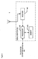
- FIG. 4 depicts a block diagram of the salient components of signal monitor 302- i in accordance with the illustrative embodiment of the present invention.
- Signal monitor 302- i comprises receiver 401, processor 402, and memory 403, interconnected as shown.
- Receiver 401 is a circuit that is capable of receiving packets from the wireless medium, in well-known fashion, and of forwarding them to processor 402. It will be clear to those skilled in the art how to make and use receiver 401.
- Processor 402 is a general-purpose processor that is capable of performing the tasks described below and with respect to Figures 6 and 7. It will be clear to those skilled in the art, after reading this specification, how to make and use processor 402.
- Memory 403 is capable of storing programs and data used by processor 402. It will be clear to those skilled in the art how to make and use memory 403.
- FIG. 5 depicts a block diagram of the salient components of location estimation server 303 in accordance with the illustrative embodiment of the present invention.
- Location estimation server 303 comprises network interface 501, processor 502, and memory 503, interconnected as shown.
- Network interface 501 is a circuit that is capable of receiving, in well-known fashion, received signal strength measurements from signal monitors 302-1 through 302- N . In some embodiments, network interface 501 receives information from signal monitors 302-1 through 302- N with which the location of the signal monitor can be determined. Network interface 501 is also capable of forwarding the information received to processor 502. It will be clear to those skilled in the art, after reading this specification, how to make and use network interface 501.
- network interface 501 receives signal strength measurements made by wireless terminal 301 ( i.e ., through an intermediate device such as an access point).
- the signal strength measurements are representative of signals that are transmitted by transmitting signal devices distributed across the network.
- Processor 502 is a general-purpose processor that is capable of performing the tasks described below and with respect to Figures 6 and 7. It will be clear to those skilled in the art, after reading this specification, how to make and use processor 502.
- Memory 503 is capable of storing programs and data used by processor 502. It will be clear to those skilled in the art how to make and use memory 503.
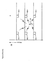
- Figure 6 depicts an example of the illustrative embodiment of the present invention.
- signal devices 602-1 through 602-15 are distributed across a multi-story office building.
- signal devices 602-1 through 602-3 are on the lowest floor depicted, while signal devices 602-13 through 602-15 are on the highest floor depicted.
- Signal devices 602-1 through 602-15 in the example are signal monitors that are capable of receiving signals and making signal measurements.
- Each floor is considered to be a "zone" within a larger space ( i . e ., the building). It will be clear, however, to those skilled in the art, after reading this specification, how to make and use embodiments of the present invention that applies the concept of zones to signify something other than the floors of a building.
- Wireless terminal 601 transmits packets of data in well-known fashion.
- One or more of signal devices 602-1 through 602-15 detect the signal corresponding to the packets of data transmitted by wireless terminal 601.
- signal devices 602-3, 602-4, 602-5, 602-6, 602-7, 602-8, 602-9, 602-11, and 602-12 are receiving and measuring the signal transmitted by wireless terminal 601.
- the signal paths of the signal that is transmitted by wireless terminal 601 traverse a plurality of zones ( i.e ., floors).
- signal devices 602-1 through 602-15 transmit signals. At least some of the signals are received by wireless terminal 601. Wireless terminal 601 makes signal measurements on the received signals and transmits the signal measurements, in well-known fashion, to location estimation server 603 ( e . g ., through an intermediary access point, etc .).
- Location estimation server 603 acquires the signal strength measurements made by one or more of signal devices 602-1 through 602-15 in accordance with the illustrative embodiment of the present invention.
- Figure 7 depicts a flowchart of the salient tasks performed by the illustrative embodiment, continuing with the example depicted in Figure 6. It will be clear to those skilled in the art which tasks depicted in Figure 7 can be performed simultaneously or in a different order than that depicted.
- each of signal devices 602-1 through 602-15 makes a signal strength measurement of a signal transmitted by wireless terminal 601.
- Location estimation server 603 acquires the signal strength measurements obtained by some or all of signal devices 602-1 through 602-15.
- the quantity m is initialized to 1.
- the quantity m is significant in that the illustrative embodiment finds the minimum value for m such that a Majority Rule holds and a Stability Rule holds. These rules are described below in detail.
- location estimation server 603 determines the m strongest-ranked signals of the received signal strength measurements (as opposed to signal strength measurements adjusted by a value K that is described below).
- location estimation server 603 determines whether or not the majority of the receivers that correspond to the m strongest-ranked signals of the received signal strength measurements are located on a particular floor ( i . e ., a candidate zone) within the building. This is referred to in the illustrative embodiment as the "Majority Rule.” If so, control proceeds to task 706. If not, control proceeds to task 705.
- location estimation server 603 adds a value K to the m + 1 st strongest of the received signal strength measurements.
- the value K is between 4 dB and 6 dB, inclusive. In other embodiments, the value K is dependent on the value of m. It will be clear to those skilled in the art, after reading this specification, how to assign a value for K .
- location estimation server 603 determines the m strongest-ranked signals of the signal strength measurements that now include the measurement that has been adjusted by the value K . Note that the action performed at task 706 might have affected the makeup of the m strongest-ranked signals.
- location estimation server 603 determines whether or not the majority of the receivers that correspond to the m strongest signals that have been re-ranked at task 707 are still located on the same floor as before (i.e ., the candidate zone) within the building. This is referred to in the illustrative embodiment as the "Stability Rule.” If so, control proceeds to task 709. If not, control proceeds to task 705.
- location estimation server 603 identifies wireless terminal 601 as being on the particular floor ( i . e ., the candidate zone) determined by applying the Majority Rule and Stability Rule.
Landscapes
- Engineering & Computer Science (AREA)
- Physics & Mathematics (AREA)
- General Physics & Mathematics (AREA)
- Radar, Positioning & Navigation (AREA)
- Remote Sensing (AREA)
- Computer Networks & Wireless Communication (AREA)
- Signal Processing (AREA)
- Mobile Radio Communication Systems (AREA)
- Position Fixing By Use Of Radio Waves (AREA)
Claims (25)
- Verfahren zum Lokalisieren eines drahtlosen Endgerätes (601), wobei ein Signal von dem drahtlosen Endgerät (601) transmittiert wird und in verschiedenen Signalstärken an einer Mehrzahl von Empfängern (602-1,...,602-15) in mehreren Zonen empfangen wird, oder wobei mehrere Signale von mehreren Sendern (602-1, ..., 602-15) in mehreren Zonen transmittiert werden und in verschiedenen Signalstärken von dem drahtlosen Endgerät (601) empfangen werden, wobei das Verfahren umfasst:- Ordnen der Signale, welche in verschiedenen Signalstärken empfangen werden, entsprechend der Signalstärke;- Betrachten der m stärksten Signale als eine erste Untergruppe, wobei m eine positive ganze Zahl ist (Schritt 703);- wenn eine Mehrzahl der m stärksten Signale der ersten Untergruppe derselben Zone zugeordnet sind, Betrachten derselben Zone als Kandidaten-Zone (Schritt 704);wobei das Verfahren gekennzeichnet ist durch:- Addieren eines Wertes k zum stärksten Signal, welches nicht in der ersten Untergruppe ist, was die Ordnung entsprechend der Signalstärke der Signale, welche in verschiedenen Signalstärken empfangen werden, ändern kann oder nicht (Schritt 706);- Betrachten der m stärksten Signale als eine zweite Untergruppe (Schritt 707);
wenn eine Mehrzahl der m stärksten Signale der zweiten Untergruppe zugeordnet ist zu derselben Zone, Bestimmen, ob dieseselbe Zone zu der Kandidaten-Zone passt (Schritt 708), und, wenn dies der Fall ist, Bestimmen, dass das drahtlose Endgerät (601) in der Kandidaten-Zone lokalisiert ist (Schritt 709). - Verfahren gemäß Anspruch 1, wobei das Verfahren zunächst m gleich 1 setzt (Schritt 702), und wobei, wenn nicht bestimmt werden kann, dass das drahtlose Endgerät (601) in der Kandidaten-Zone lokalisiert ist, das Verfahren m auf 2 setzt (Schritt 705) und die Analyse der ersten und zweiten Untergruppe (Schritte 704 und 708) wiederholt, um zu versuchen, das drahtlose Endgerät zu lokalisieren (Schritt 709).
- Verfahren gemäß Anspruch 2, wobei, wenn das drahtlose Endgerät (601), wenn m gleich 2 ist, nicht als in der Kandidaten-Zone lokalisiert bestimmt werden kann, das Verfahren m auf 3 setzt (Schritt 705) und die Analyse der ersten und zweiten Untergruppe wiederholt (Schritte 704 und 706), um zu versuchen, das drahtlose Endgerät zu lokalisieren (Schritt 709).
- Verfahren gemäß Anspruch 1, wobei das Verfahren zunächst m gleich der positiven ganzen Zahl setzt (Schritt 702), und wobei, wenn das drahtlose Endgerät (610) nicht als in der Kandidaten-Zone lokalisiert bestimmt werden kann, das Verfahren m gleich der positiven ganzen Zahl plus eins setzt (Schritt 705) und die Analyse der ersten und zweiten Untergruppe wiederholt (Schritte 704 und 708), um zu versuchen, das drahtlose Endgerät zu lokalisieren (Schritt 709).
- Verfahren gemäß Anspruch 4, wobei, wenn das drahtlose Endgerät (601) nach einer ersten Erhöhung von m nicht als in der Kandidaten-Zone lokalisiert bestimmt werden kann, das Verfahren einen Zyklus der Erhöhung von m fortsetzt (Schritt 705) und die Analyse der ersten und zweiten Untergruppe wiederholt (Schritte 704 und 708), um zu versuchen, das drahtlose Endgerät zu lokalisieren (Schritt 709).
- Verfahren gemäß Anspruch 1, wobei die mehreren Zonen Stockwerken eines Gebäudes entsprechen.
- Verfahren gemäß Anspruch 1, wobei der Wert k gleich einem Wert zwischen einschließlich 4 und einschließlich 6 dB ist.
- Verfahren gemäß Anspruch 1, wobei der Wert k gleich einem Betrag ist, der vom Wert von m abhängt.
- Verfahren gemäß Anspruch 1, wobei die Signale, welche in verschiedenen Stärken empfangen werden, spezifisch für die Lokalisierung des drahtlosen Endgerätes (601) sind.
- Verfahren gemäß Anspruch 1, wobei die Signale, welche in verschiedenen Stärken empfangen werden, Datenpakete sind, mittels derer das drahtlose Endgerät (601) mit einem Zugangspunkt kommuniziert.
- Verfahren gemäß Anspruch 1, wobei die in verschiedenen Stärken empfangenen Signale von dem drahtlosen Endgerät (601) empfangen werden.
- Verfahren gemäß Anspruch 1, wobei die Signale, welche in verschiedenen Stärken empfangen werden, von der Mehrzahl von Empfängern (602-1, ..., 602-15) empfangen werden.
- Vorrichtung, eingerichtet zur Durchführung eines Verfahrens zur Lokalisierung eines drahtlosen Endgerätes (601), wobei ein Signal von dem drahtlosen Endgerät (601) transmittiert wird und in verschiedenen Signalstärken an einer Mehrzahl von Empfängern (602-1, ..., 602-15) in mehreren Zonen empfangen wird, oder wobei mehrere Signale von einer Mehrzahl von Sendern (602-1, ..., 602-15) in mehreren Zonen transmittiert werden und in verschiedenen Signalstärken von dem drahtlosen Endgerät (601) empfangen werden, wobei die Vorrichtung umfasst:Einen Prozessor (502), wobei der Prozessor eingerichtet ist, um:wobei die Vorrichtung dadurch gekennzeichnet ist, dass der Prozessor (502) eingerichtet ist, um:die Signale, die in verschiedenen Signalstärken empfangen werden, in der Reihenfolge der Signalstärke zu ordnen;die m stärksten Signale als eine erste Untergruppe zu betrachten, wobei m eine positive ganze Zahl ist (Schritt 703);wenn eine Mehrzahl der m stärksten Signale der ersten Untergruppe derselben Zone zugeordnet sind, Betrachten derselben Zone als Kandidaten-Zone (Schritt 704);einen Wert k zum stärksten Signal, welches nicht in der ersten Untergruppe ist, zu addieren, was die Ordnung entsprechend der Reihenfolge der Signalstärken der Signale, die in verschiedenen Signalstärken empfangen werden, ändern kann oder nicht (Schritt 706);die m stärksten Signale als zweite Untergruppe zu betrachten (Schritt 707);wenn eine Mehrzahl der m stärksten Signale der zweiten Untergruppe derselben Zone zugeordnet ist, zu bestimmen, ob dieselbe Zone zu der Kandidaten-Zone passt (Schritt 708), und, wenn dies der Fall ist, zu bestimmen, dass das drahtlose Endgerät (601) in der Kandidaten-Zone lokalisiert ist (Schritt 709).
- Vorrichtung gemäß Anspruch 13, wobei der Prozessor (502) eingerichtet ist, um zunächst m gleich 1 zu setzen (Schritt 702), und wobei, wenn das drahtlose Endgerät (601) nicht als in der Kandidaten-Zone lokalisiert bestimmt werden kann, der Prozessor (502) eingerichtet ist, um m gleich 2 zu setzen (Schritt 705) und die Analyse der ersten und zweiten Untergruppe zu wiederholen (Schritte 704 und 708), um zu versuchen, das drahtlose Endgerät zu lokalisieren (Schritt 709).
- Vorrichtung gemäß Anspruch 14, wobei, wenn das drahtlose Endgerät (601) nicht als in der Kandidaten-Zone lokalisiert bestimmt werden kann, wenn m gleich 2 ist, der Prozessor (502) eingerichtet ist, m gleich 3 zu setzen (Schritt 705) und die Analyse der ersten und zweiten Untergruppe zu wiederholen, um zu versuchen, das drahtlose Endgerät zu lokalisieren (Schritt 709).
- Vorrichtung gemäß Anspruch 13, wobei der Prozessor (502) eingerichtet ist, um zunächst m gleich der positiven ganzen Zahl zu setzen (Schritt 702), und wobei, wenn das drahtlose Endgerät (601) nicht als in der Kandidaten-Zone lokalisiert bestimmt werden kann, der Prozessor (502) eingerichtet ist, um m auf einen Wert gleich der positiven ganzen Zahl plus eins zu erhöhen (Schritt 705) und die Analyse der ersten und zweiten Untergruppe zu wiederholen (Schritte 704 und 708), um zu versuchen, das drahtlose Endgerät zu lokalisieren (Schritt 709).
- Vorrichtung gemäß Anspruch 16, wobei, wenn das drahtlose Endgerät (601) nach einer ersten Erhöhung von m nicht als in der Kandidaten-Zone lokalisiert bestimmt werden kann, der Prozessor (502) eingerichtet ist, um einen Zyklus einer Erhöhung von m fortzusetzen (Schritt 705) und die Analyse der ersten und zweiten Untergruppen (Schritte 704 und 708) zu wiederholen, um zu versuchen, das drahtlose Endgerät zu lokalisieren (Schritt 709).
- Vorrichtung gemäß Anspruch 13, wobei die mehreren Zonen Stockwerken eines Gebäudes entsprechen.
- Vorrichtung gemäß Anspruch 13, wobei der Wert k einen Betrag zwischen einschließlich 4 und einschließlich 6 dB hat.
- Vorrichtung gemäß Anspruch 13, wobei der Wert k gleich einem Betrag ist, welcher vom Wert von m abhängt.
- Vorrichtung gemäß Anspruch 13, wobei die Signale, welche in verschiedenen Signalstärken empfangen werden, spezifisch für die Lokalisierung des drahtlosen Endgerätes (601) sind.
- Vorrichtung gemäß Anspruch 13, wobei die Signale, welche in verschiedenen Signalstärken empfangen werden, Datenpakete sind, mittels derer das drahtlose Endgerät (601) mit einem Zugangspunkt kommuniziert.
- Vorrichtung gemäß Anspruch 13, wobei die Vorrichtung eingerichtet ist, dass die Signale, welche in verschiedenen Signalstärken empfangen werden, von dem drahtlosen Endgerät (601) empfangen werden und zu dem Prozessor (502) transmittiert werden.
- Vorrichtung gemäß Anspruch 13, wobei die Vorrichtung eingerichtet ist, dass die Signale, welche in verschiedenen Signalstärken empfangen werden, von den mehreren Empfängern (602-1, ..., 602-15) empfangen werden und an den Prozessor (502) transmittiert werden.
- Vorrichtung gemäß Anspruch 24, wobei die Vorrichtung eingerichtet ist, dass die Mehrzahl von Empfängern (602-1, ..., 602-15) auch Empfängerort-Informationen an den Prozessor (502) transmittieren.
Applications Claiming Priority (2)
| Application Number | Priority Date | Filing Date | Title |
|---|---|---|---|
| US776588 | 2004-02-11 | ||
| US10/776,588 US7272394B2 (en) | 2004-02-11 | 2004-02-11 | Location estimation of wireless terminals in a multi-story environment |
Publications (2)
| Publication Number | Publication Date |
|---|---|
| EP1569490A1 EP1569490A1 (de) | 2005-08-31 |
| EP1569490B1 true EP1569490B1 (de) | 2007-02-07 |
Family
ID=34750446
Family Applications (1)
| Application Number | Title | Priority Date | Filing Date |
|---|---|---|---|
| EP05002772A Expired - Lifetime EP1569490B1 (de) | 2004-02-11 | 2005-02-10 | Schätzung der Lokalisierung von mobile Endgeräten in einem mehrstöckingen Gebäude |
Country Status (7)
| Country | Link |
|---|---|
| US (1) | US7272394B2 (de) |
| EP (1) | EP1569490B1 (de) |
| JP (1) | JP4648026B2 (de) |
| KR (1) | KR101060989B1 (de) |
| AT (1) | ATE353532T1 (de) |
| CA (1) | CA2496598C (de) |
| DE (1) | DE602005000533T2 (de) |
Families Citing this family (47)
| Publication number | Priority date | Publication date | Assignee | Title |
|---|---|---|---|---|
| US6839562B2 (en) * | 2000-04-11 | 2005-01-04 | Telecommunication Systems, Inc. | Intelligent delivery agent for short message distribution center |
| US6658260B2 (en) | 2001-09-05 | 2003-12-02 | Telecommunication Systems, Inc. | Inter-carrier short messaging service providing phone number only experience |
| US8195205B2 (en) | 2004-05-06 | 2012-06-05 | Telecommunication Systems, Inc. | Gateway application to support use of a single internet address domain for routing messages to multiple multimedia message service centers |
| US7236128B2 (en) * | 2004-06-23 | 2007-06-26 | Cognio, Inc. | System and method for locating radio emitters using self-calibrated path loss computation |
| US7430425B2 (en) | 2005-05-17 | 2008-09-30 | Telecommunication Systems, Inc. | Inter-carrier digital message with user data payload service providing phone number only experience |
| US7698061B2 (en) | 2005-09-23 | 2010-04-13 | Scenera Technologies, Llc | System and method for selecting and presenting a route to a user |
| US8886210B1 (en) * | 2007-01-16 | 2014-11-11 | Cisco Technology, Inc. | Resolving ambiguity with respect to locationing and classification of wireless transmitters |
| US8155662B2 (en) * | 2007-02-19 | 2012-04-10 | Microsoft Corporation | Self-configuring wireless network location system |
| ES2612559T3 (es) * | 2007-03-07 | 2017-05-17 | Wirelesswerx International, Inc. | Método y sistema para proporcionar mensajes de área específicos |
| JP4616315B2 (ja) * | 2007-08-13 | 2011-01-19 | 株式会社エヌ・ティ・ティ・ドコモ | エリア推定システム、エリア推定方法及びエリア推定装置 |
| JP2009055228A (ja) | 2007-08-24 | 2009-03-12 | Sony Corp | 無線通信システム、無線通信装置及び無線通信方法 |
| US7894412B2 (en) * | 2007-09-07 | 2011-02-22 | Cisco Technology, Inc. | Floor determination for a wireless device |
| JP4840395B2 (ja) * | 2008-04-18 | 2011-12-21 | ソニー株式会社 | 情報処理装置、プログラム、情報処理方法、および情報処理システム |
| WO2009148466A1 (en) * | 2008-06-05 | 2009-12-10 | Relume Technologies, Inc. | Networked light control system |
| US8089371B2 (en) * | 2008-07-30 | 2012-01-03 | Cisco Technology, Inc. | Logical floor determination for a wireless device using weighted AP received signal strengths |
| WO2010045466A2 (en) * | 2008-10-15 | 2010-04-22 | Jadi, Inc. | Multi-level tracking |
| US8321509B2 (en) | 2009-02-02 | 2012-11-27 | Waldeck Technology, Llc | Handling crowd requests for large geographic areas |
| US7940715B2 (en) * | 2009-03-03 | 2011-05-10 | Src, Inc. | Entropic based activity passive detection and monitoring system |
| US20110025464A1 (en) * | 2009-07-30 | 2011-02-03 | Awarepoint Corporation | Antenna Diversity For Wireless Tracking System And Method |
| CA2779126C (en) | 2009-10-30 | 2015-12-29 | Tata Consultancy Services Ltd. | System for wireless location estimation using radio transceivers with polarization diversity |
| US8560608B2 (en) * | 2009-11-06 | 2013-10-15 | Waldeck Technology, Llc | Crowd formation based on physical boundaries and other rules |
| US8966390B2 (en) * | 2009-12-29 | 2015-02-24 | Nokia Corporation | Method and apparatus for visually indicating location probability |
| US8704713B2 (en) * | 2010-01-22 | 2014-04-22 | Qualcomm Incorporated | Methods and apparatuses for use in identifying wireless transmitting devices for use in estimating a location of a mobile device |
| JP5732863B2 (ja) * | 2011-01-17 | 2015-06-10 | ソニー株式会社 | 位置推定装置、位置推定方法、プログラム、および位置推定システム |
| KR101422251B1 (ko) | 2011-01-31 | 2014-07-22 | 주식회사 케이티 | 액세스 포인트를 이용한 실내 위치 측정 방법과 이를 위한 장치 |
| US8700054B2 (en) * | 2011-06-10 | 2014-04-15 | Google Inc. | Prediction of indoor level and location using a three stage process |
| US8706137B2 (en) | 2011-08-02 | 2014-04-22 | Qualcomm Incorporated | Likelihood of mobile device portal transition |
| US9053624B2 (en) | 2012-01-17 | 2015-06-09 | Avaya Inc. | System and method for tracking in multi-story buildings |
| US8949159B2 (en) | 2012-01-20 | 2015-02-03 | Avaya Inc. | System and method for automatic merging of real and virtual environments |
| US8639265B1 (en) * | 2012-02-14 | 2014-01-28 | Sprint Spectrum L.P. | Advertising wireless coverage areas based on device altitude |
| US8818403B1 (en) | 2012-02-14 | 2014-08-26 | Sprint Spectrum L.P. | Adjusting wireless coverage area resource assignment based on device altitude |
| US8818402B1 (en) | 2012-02-14 | 2014-08-26 | Sprint Spectrum L.P. | Adjusting initial wireless coverage area transmit power based on device altitude |
| JP2013200706A (ja) * | 2012-03-26 | 2013-10-03 | Hitachi Information & Telecommunication Engineering Ltd | 入退連動システム |
| US9696421B2 (en) | 2013-03-15 | 2017-07-04 | Src, Inc. | Through wall sensing system using WiFi/cellular radar |
| CN104995930B (zh) * | 2013-03-19 | 2019-07-16 | 英特尔公司 | 用于基于位置服务的建筑物楼层确定 |
| WO2015098214A1 (ja) * | 2013-12-27 | 2015-07-02 | ソニー株式会社 | 情報処理装置、情報処理方法およびプログラム |
| US9374678B2 (en) * | 2014-02-28 | 2016-06-21 | Texas Instruments Incorporated | Kalman filter iteratively performing time/measurement update of user/relative floor locations |
| US9918202B2 (en) * | 2014-05-12 | 2018-03-13 | Microsoft Technology Licensing, Llc | Adaptive position determination |
| US9894502B2 (en) * | 2014-05-21 | 2018-02-13 | Verizon Patent And Licensing Inc. | Floor identification for emergency calls |
| US9510319B2 (en) * | 2014-12-10 | 2016-11-29 | Texas Instruments Incorporated | Method and system for location estimation |
| WO2017179109A1 (ja) * | 2016-04-11 | 2017-10-19 | 富士通株式会社 | 位置推定プログラム、位置推定方法、及び位置推定装置 |
| US11584613B2 (en) | 2017-06-23 | 2023-02-21 | Otis Elevator Comapny | Determination for motion of passenger over elevator landing area |
| DE112018003975T5 (de) * | 2017-08-31 | 2020-04-16 | Murata Manufacturing Co., Ltd. | Positionsschätzsystem |
| NZ772361A (en) * | 2018-10-19 | 2025-12-19 | PwC Product Sales LLC | Geolocation system |
| JP2020134469A (ja) * | 2019-02-26 | 2020-08-31 | 株式会社富士通アドバンストエンジニアリング | 無線測位システム、無線測位方法および無線測位プログラム |
| US11337176B2 (en) | 2020-06-12 | 2022-05-17 | Cisco Technology, Inc. | Access point based location system for high density wifi deployments |
| US12429334B1 (en) | 2024-05-15 | 2025-09-30 | Cary N. Davids | System and method for determining vertical position in multi-floor building |
Family Cites Families (11)
| Publication number | Priority date | Publication date | Assignee | Title |
|---|---|---|---|---|
| US6418318B1 (en) * | 1995-12-12 | 2002-07-09 | At&T Wireless Services, Inc. | Method for selecting a preferable wireless communications service provider in a multi-service provider environment |
| JP3161334B2 (ja) * | 1996-07-29 | 2001-04-25 | 松下電器産業株式会社 | 位置検出装置 |
| WO1998010307A1 (en) * | 1996-09-09 | 1998-03-12 | Dennis Jay Dupray | Location of a mobile station |
| US6119009A (en) * | 1997-09-18 | 2000-09-12 | Lucent Technologies, Inc. | Method and apparatus for modeling the propagation of wireless signals in buildings |
| US6393294B1 (en) * | 1998-09-22 | 2002-05-21 | Polaris Wireless, Inc. | Location determination using RF fingerprinting |
| WO2000050919A2 (en) | 1999-02-25 | 2000-08-31 | Microsoft Corporation | Method and computer-readable medium for locating and tracking a user in a wireless network using a table of dignal data |
| GB0102361D0 (en) * | 2001-01-30 | 2001-03-14 | Nokia Networks Oy | Provision of services in a communication system |
| JP2005525003A (ja) | 2001-09-05 | 2005-08-18 | ニューベリイ ネットワークス,インコーポレーテッド | 無線ネットワークにおける位置検出および場所追跡 |
| US6873852B2 (en) * | 2002-01-10 | 2005-03-29 | Telefonaktiebolaget Lm Ericsson (Publ) | System and method of estimating the position of a mobile terminal in a radio telecommunications network |
| US6664925B1 (en) | 2002-05-02 | 2003-12-16 | Microsoft Corporation | Method and system for determining the location of a mobile computer |
| US7257411B2 (en) * | 2002-12-27 | 2007-08-14 | Ntt Docomo, Inc. | Selective fusion location estimation (SELFLOC) for wireless access technologies |
-
2004
- 2004-02-11 US US10/776,588 patent/US7272394B2/en not_active Expired - Lifetime
-
2005
- 2005-02-04 KR KR1020050010385A patent/KR101060989B1/ko not_active Expired - Fee Related
- 2005-02-10 AT AT05002772T patent/ATE353532T1/de not_active IP Right Cessation
- 2005-02-10 JP JP2005033824A patent/JP4648026B2/ja not_active Expired - Fee Related
- 2005-02-10 CA CA002496598A patent/CA2496598C/en not_active Expired - Lifetime
- 2005-02-10 DE DE602005000533T patent/DE602005000533T2/de not_active Expired - Lifetime
- 2005-02-10 EP EP05002772A patent/EP1569490B1/de not_active Expired - Lifetime
Also Published As
| Publication number | Publication date |
|---|---|
| CA2496598C (en) | 2010-01-19 |
| JP4648026B2 (ja) | 2011-03-09 |
| US7272394B2 (en) | 2007-09-18 |
| DE602005000533T2 (de) | 2007-05-31 |
| JP2005229617A (ja) | 2005-08-25 |
| EP1569490A1 (de) | 2005-08-31 |
| KR20060041702A (ko) | 2006-05-12 |
| CA2496598A1 (en) | 2005-08-11 |
| KR101060989B1 (ko) | 2011-08-31 |
| ATE353532T1 (de) | 2007-02-15 |
| DE602005000533D1 (de) | 2007-03-22 |
| US20050176406A1 (en) | 2005-08-11 |
Similar Documents
| Publication | Publication Date | Title |
|---|---|---|
| EP1569490B1 (de) | Schätzung der Lokalisierung von mobile Endgeräten in einem mehrstöckingen Gebäude | |
| EP1575325B1 (de) | Bestimmung des Standortes von preiswerten drahtlosen Endgeräten durch Verwendung von Signalstärkemessungen | |
| Hightower et al. | Design and calibration of the spoton ad-hoc location sensing system | |
| US8014804B2 (en) | Associating a wireless station with an access point | |
| US9435876B2 (en) | Autonomous muting indication to enable improved time difference of arrival measurements | |
| EP2115941B1 (de) | Selbstkonfigurierendes drahtlosnetzwerk-ortungssystem | |
| KR101246621B1 (ko) | 무선 통신 시스템 내에서의 스마트 안테나에 대한 측정 지원 | |
| CN101867963A (zh) | 无线局域网接入方法、设备及系统与无线接入点 | |
| US20050014497A1 (en) | Method for tracking location of a mobile unit | |
| EP1647160A1 (de) | Ortsschätzung drahtloser endgeräte durch mustervergleich deduzierter und empirischer signalstärkenmessungen | |
| CN114363798A (zh) | 设备定位 | |
| Yeung et al. | Wireless LAN positioning based on received signal strength from mobile device and access points | |
| CN104488317B (zh) | 扰码解析 | |
| WO2023223217A1 (en) | Systems and methods for selecting and updating a set of sounding devices | |
| CN107333309A (zh) | 一种无线信道的切换方法及装置 | |
| WO2021109440A1 (en) | Method of prior channel information transmission | |
| CN121368912A (zh) | 用于建立测量系统的运营移动通信连接的方法 | |
| JP2008153821A (ja) | 無線通信システム、端末、基地局及び制御プログラム | |
| US20250212154A1 (en) | Area determination system, area determination method, and program | |
| CN101084605A (zh) | 无线通信系统中智能天线测量支持 | |
| CN121367999A (zh) | 参考信号的测量方法及传输接收节点trp的选择方法 | |
| CN119096160A (zh) | 用于定时和参考信号接收路径功率的ue测量的对齐的方法 | |
| CN113423138A (zh) | 移动终端的定位方法、终端设备及存储介质 |
Legal Events
| Date | Code | Title | Description |
|---|---|---|---|
| PUAI | Public reference made under article 153(3) epc to a published international application that has entered the european phase |
Free format text: ORIGINAL CODE: 0009012 |
|
| AK | Designated contracting states |
Kind code of ref document: A1 Designated state(s): AT BE BG CH CY CZ DE DK EE ES FI FR GB GR HU IE IS IT LI LT LU MC NL PL PT RO SE SI SK TR |
|
| AX | Request for extension of the european patent |
Extension state: AL BA HR LV MK YU |
|
| 17P | Request for examination filed |
Effective date: 20051025 |
|
| AKX | Designation fees paid |
Designated state(s): AT BE BG CH CY CZ DE DK EE ES FI FR GB GR HU IE IS IT LI LT LU MC NL PL PT RO SE SI SK TR |
|
| RTI1 | Title (correction) |
Free format text: LOCATION ESTIMATION OF WIRELESS TERMINALS IN A MULTISTORY BUILDING |
|
| GRAP | Despatch of communication of intention to grant a patent |
Free format text: ORIGINAL CODE: EPIDOSNIGR1 |
|
| GRAS | Grant fee paid |
Free format text: ORIGINAL CODE: EPIDOSNIGR3 |
|
| GRAA | (expected) grant |
Free format text: ORIGINAL CODE: 0009210 |
|
| AK | Designated contracting states |
Kind code of ref document: B1 Designated state(s): AT BE BG CH CY CZ DE DK EE ES FI FR GB GR HU IE IS IT LI LT LU MC NL PL PT RO SE SI SK TR |
|
| PG25 | Lapsed in a contracting state [announced via postgrant information from national office to epo] |
Ref country code: PL Free format text: LAPSE BECAUSE OF FAILURE TO SUBMIT A TRANSLATION OF THE DESCRIPTION OR TO PAY THE FEE WITHIN THE PRESCRIBED TIME-LIMIT Effective date: 20070207 Ref country code: LI Free format text: LAPSE BECAUSE OF FAILURE TO SUBMIT A TRANSLATION OF THE DESCRIPTION OR TO PAY THE FEE WITHIN THE PRESCRIBED TIME-LIMIT Effective date: 20070207 Ref country code: AT Free format text: LAPSE BECAUSE OF FAILURE TO SUBMIT A TRANSLATION OF THE DESCRIPTION OR TO PAY THE FEE WITHIN THE PRESCRIBED TIME-LIMIT Effective date: 20070207 Ref country code: DK Free format text: LAPSE BECAUSE OF FAILURE TO SUBMIT A TRANSLATION OF THE DESCRIPTION OR TO PAY THE FEE WITHIN THE PRESCRIBED TIME-LIMIT Effective date: 20070207 Ref country code: BE Free format text: LAPSE BECAUSE OF FAILURE TO SUBMIT A TRANSLATION OF THE DESCRIPTION OR TO PAY THE FEE WITHIN THE PRESCRIBED TIME-LIMIT Effective date: 20070207 Ref country code: CH Free format text: LAPSE BECAUSE OF FAILURE TO SUBMIT A TRANSLATION OF THE DESCRIPTION OR TO PAY THE FEE WITHIN THE PRESCRIBED TIME-LIMIT Effective date: 20070207 Ref country code: SI Free format text: LAPSE BECAUSE OF FAILURE TO SUBMIT A TRANSLATION OF THE DESCRIPTION OR TO PAY THE FEE WITHIN THE PRESCRIBED TIME-LIMIT Effective date: 20070207 |
|
| REG | Reference to a national code |
Ref country code: GB Ref legal event code: FG4D |
|
| PGFP | Annual fee paid to national office [announced via postgrant information from national office to epo] |
Ref country code: AT Payment date: 20070227 Year of fee payment: 3 Ref country code: DK Payment date: 20070227 Year of fee payment: 3 Ref country code: IE Payment date: 20070227 Year of fee payment: 3 Ref country code: MC Payment date: 20070227 Year of fee payment: 3 |
|
| PGFP | Annual fee paid to national office [announced via postgrant information from national office to epo] |
Ref country code: LU Payment date: 20070228 Year of fee payment: 3 |
|
| REG | Reference to a national code |
Ref country code: CH Ref legal event code: EP |
|
| PGFP | Annual fee paid to national office [announced via postgrant information from national office to epo] |
Ref country code: ES Payment date: 20070306 Year of fee payment: 3 |
|
| REG | Reference to a national code |
Ref country code: IE Ref legal event code: FG4D |
|
| REF | Corresponds to: |
Ref document number: 602005000533 Country of ref document: DE Date of ref document: 20070322 Kind code of ref document: P |
|
| PG25 | Lapsed in a contracting state [announced via postgrant information from national office to epo] |
Ref country code: BG Free format text: LAPSE BECAUSE OF FAILURE TO SUBMIT A TRANSLATION OF THE DESCRIPTION OR TO PAY THE FEE WITHIN THE PRESCRIBED TIME-LIMIT Effective date: 20070507 |
|
| PG25 | Lapsed in a contracting state [announced via postgrant information from national office to epo] |
Ref country code: ES Free format text: LAPSE BECAUSE OF FAILURE TO SUBMIT A TRANSLATION OF THE DESCRIPTION OR TO PAY THE FEE WITHIN THE PRESCRIBED TIME-LIMIT Effective date: 20070518 |
|
| REG | Reference to a national code |
Ref country code: SE Ref legal event code: TRGR |
|
| PG25 | Lapsed in a contracting state [announced via postgrant information from national office to epo] |
Ref country code: IS Free format text: LAPSE BECAUSE OF FAILURE TO SUBMIT A TRANSLATION OF THE DESCRIPTION OR TO PAY THE FEE WITHIN THE PRESCRIBED TIME-LIMIT Effective date: 20070607 |
|
| PG25 | Lapsed in a contracting state [announced via postgrant information from national office to epo] |
Ref country code: PT Free format text: LAPSE BECAUSE OF FAILURE TO SUBMIT A TRANSLATION OF THE DESCRIPTION OR TO PAY THE FEE WITHIN THE PRESCRIBED TIME-LIMIT Effective date: 20070709 |
|
| ET | Fr: translation filed | ||
| REG | Reference to a national code |
Ref country code: CH Ref legal event code: PL |
|
| PG25 | Lapsed in a contracting state [announced via postgrant information from national office to epo] |
Ref country code: SK Free format text: LAPSE BECAUSE OF FAILURE TO SUBMIT A TRANSLATION OF THE DESCRIPTION OR TO PAY THE FEE WITHIN THE PRESCRIBED TIME-LIMIT Effective date: 20070207 |
|
| PLBE | No opposition filed within time limit |
Free format text: ORIGINAL CODE: 0009261 |
|
| STAA | Information on the status of an ep patent application or granted ep patent |
Free format text: STATUS: NO OPPOSITION FILED WITHIN TIME LIMIT |
|
| PG25 | Lapsed in a contracting state [announced via postgrant information from national office to epo] |
Ref country code: CZ Free format text: LAPSE BECAUSE OF FAILURE TO SUBMIT A TRANSLATION OF THE DESCRIPTION OR TO PAY THE FEE WITHIN THE PRESCRIBED TIME-LIMIT Effective date: 20070207 Ref country code: RO Free format text: LAPSE BECAUSE OF FAILURE TO SUBMIT A TRANSLATION OF THE DESCRIPTION OR TO PAY THE FEE WITHIN THE PRESCRIBED TIME-LIMIT Effective date: 20070207 |
|
| PGFP | Annual fee paid to national office [announced via postgrant information from national office to epo] |
Ref country code: BE Payment date: 20070413 Year of fee payment: 3 |
|
| 26N | No opposition filed |
Effective date: 20071108 |
|
| PG25 | Lapsed in a contracting state [announced via postgrant information from national office to epo] |
Ref country code: LT Free format text: LAPSE BECAUSE OF FAILURE TO SUBMIT A TRANSLATION OF THE DESCRIPTION OR TO PAY THE FEE WITHIN THE PRESCRIBED TIME-LIMIT Effective date: 20070207 |
|
| PG25 | Lapsed in a contracting state [announced via postgrant information from national office to epo] |
Ref country code: GR Free format text: LAPSE BECAUSE OF FAILURE TO SUBMIT A TRANSLATION OF THE DESCRIPTION OR TO PAY THE FEE WITHIN THE PRESCRIBED TIME-LIMIT Effective date: 20070508 |
|
| PG25 | Lapsed in a contracting state [announced via postgrant information from national office to epo] |
Ref country code: MC Free format text: LAPSE BECAUSE OF NON-PAYMENT OF DUE FEES Effective date: 20080228 |
|
| PG25 | Lapsed in a contracting state [announced via postgrant information from national office to epo] |
Ref country code: IE Free format text: LAPSE BECAUSE OF NON-PAYMENT OF DUE FEES Effective date: 20080211 Ref country code: EE Free format text: LAPSE BECAUSE OF FAILURE TO SUBMIT A TRANSLATION OF THE DESCRIPTION OR TO PAY THE FEE WITHIN THE PRESCRIBED TIME-LIMIT Effective date: 20070207 |
|
| REG | Reference to a national code |
Ref country code: GB Ref legal event code: 732E Free format text: REGISTERED BETWEEN 20090430 AND 20090506 |
|
| PGFP | Annual fee paid to national office [announced via postgrant information from national office to epo] |
Ref country code: FI Payment date: 20090212 Year of fee payment: 5 Ref country code: NL Payment date: 20090203 Year of fee payment: 5 |
|
| PG25 | Lapsed in a contracting state [announced via postgrant information from national office to epo] |
Ref country code: CY Free format text: LAPSE BECAUSE OF FAILURE TO SUBMIT A TRANSLATION OF THE DESCRIPTION OR TO PAY THE FEE WITHIN THE PRESCRIBED TIME-LIMIT Effective date: 20070207 |
|
| PGFP | Annual fee paid to national office [announced via postgrant information from national office to epo] |
Ref country code: IT Payment date: 20090212 Year of fee payment: 5 Ref country code: SE Payment date: 20090206 Year of fee payment: 5 |
|
| PG25 | Lapsed in a contracting state [announced via postgrant information from national office to epo] |
Ref country code: HU Free format text: LAPSE BECAUSE OF FAILURE TO SUBMIT A TRANSLATION OF THE DESCRIPTION OR TO PAY THE FEE WITHIN THE PRESCRIBED TIME-LIMIT Effective date: 20070808 Ref country code: TR Free format text: LAPSE BECAUSE OF FAILURE TO SUBMIT A TRANSLATION OF THE DESCRIPTION OR TO PAY THE FEE WITHIN THE PRESCRIBED TIME-LIMIT Effective date: 20070207 |
|
| GBPC | Gb: european patent ceased through non-payment of renewal fee |
Effective date: 20090210 |
|
| PG25 | Lapsed in a contracting state [announced via postgrant information from national office to epo] |
Ref country code: GB Free format text: LAPSE BECAUSE OF NON-PAYMENT OF DUE FEES Effective date: 20090210 |
|
| PG25 | Lapsed in a contracting state [announced via postgrant information from national office to epo] |
Ref country code: LU Free format text: LAPSE BECAUSE OF NON-PAYMENT OF DUE FEES Effective date: 20080210 |
|
| REG | Reference to a national code |
Ref country code: NL Ref legal event code: V1 Effective date: 20100901 |
|
| EUG | Se: european patent has lapsed | ||
| PG25 | Lapsed in a contracting state [announced via postgrant information from national office to epo] |
Ref country code: FI Free format text: LAPSE BECAUSE OF NON-PAYMENT OF DUE FEES Effective date: 20100210 |
|
| PG25 | Lapsed in a contracting state [announced via postgrant information from national office to epo] |
Ref country code: NL Free format text: LAPSE BECAUSE OF NON-PAYMENT OF DUE FEES Effective date: 20100901 |
|
| PG25 | Lapsed in a contracting state [announced via postgrant information from national office to epo] |
Ref country code: IT Free format text: LAPSE BECAUSE OF NON-PAYMENT OF DUE FEES Effective date: 20100210 |
|
| PG25 | Lapsed in a contracting state [announced via postgrant information from national office to epo] |
Ref country code: SE Free format text: LAPSE BECAUSE OF NON-PAYMENT OF DUE FEES Effective date: 20100211 |
|
| REG | Reference to a national code |
Ref country code: FR Ref legal event code: PLFP Year of fee payment: 12 |
|
| REG | Reference to a national code |
Ref country code: FR Ref legal event code: PLFP Year of fee payment: 13 |
|
| REG | Reference to a national code |
Ref country code: FR Ref legal event code: PLFP Year of fee payment: 14 |
|
| PGFP | Annual fee paid to national office [announced via postgrant information from national office to epo] |
Ref country code: DE Payment date: 20220225 Year of fee payment: 18 |
|
| PGFP | Annual fee paid to national office [announced via postgrant information from national office to epo] |
Ref country code: FR Payment date: 20220223 Year of fee payment: 18 |
|
| REG | Reference to a national code |
Ref country code: DE Ref legal event code: R119 Ref document number: 602005000533 Country of ref document: DE |
|
| PG25 | Lapsed in a contracting state [announced via postgrant information from national office to epo] |
Ref country code: FR Free format text: LAPSE BECAUSE OF NON-PAYMENT OF DUE FEES Effective date: 20230228 Ref country code: DE Free format text: LAPSE BECAUSE OF NON-PAYMENT OF DUE FEES Effective date: 20230901 |