EP1569420A2 - Gelenk für geteilte Tastaturen für ein tragbares Kommunikations- und Spielgerät - Google Patents
Gelenk für geteilte Tastaturen für ein tragbares Kommunikations- und Spielgerät Download PDFInfo
- Publication number
- EP1569420A2 EP1569420A2 EP05003072A EP05003072A EP1569420A2 EP 1569420 A2 EP1569420 A2 EP 1569420A2 EP 05003072 A EP05003072 A EP 05003072A EP 05003072 A EP05003072 A EP 05003072A EP 1569420 A2 EP1569420 A2 EP 1569420A2
- Authority
- EP
- European Patent Office
- Prior art keywords
- hinge
- housing
- swing
- set forth
- key
- Prior art date
- Legal status (The legal status is an assumption and is not a legal conclusion. Google has not performed a legal analysis and makes no representation as to the accuracy of the status listed.)
- Withdrawn
Links
Images




Classifications
-
- H—ELECTRICITY
- H04—ELECTRIC COMMUNICATION TECHNIQUE
- H04M—TELEPHONIC COMMUNICATION
- H04M1/00—Substation equipment, e.g. for use by subscribers
- H04M1/02—Constructional features of telephone sets
- H04M1/0202—Portable telephone sets, e.g. cordless phones, mobile phones or bar type handsets
- H04M1/0206—Portable telephones comprising a plurality of mechanically joined movable body parts, e.g. hinged housings
- H04M1/0247—Portable telephones comprising a plurality of mechanically joined movable body parts, e.g. hinged housings comprising more than two body parts
-
- H—ELECTRICITY
- H04—ELECTRIC COMMUNICATION TECHNIQUE
- H04M—TELEPHONIC COMMUNICATION
- H04M1/00—Substation equipment, e.g. for use by subscribers
- H04M1/02—Constructional features of telephone sets
- H04M1/23—Construction or mounting of dials or of equivalent devices; Means for facilitating the use thereof
-
- A—HUMAN NECESSITIES
- A63—SPORTS; GAMES; AMUSEMENTS
- A63F—CARD, BOARD, OR ROULETTE GAMES; INDOOR GAMES USING SMALL MOVING PLAYING BODIES; VIDEO GAMES; GAMES NOT OTHERWISE PROVIDED FOR
- A63F2300/00—Features of games using an electronically generated display having two or more dimensions, e.g. on a television screen, showing representations related to the game
- A63F2300/10—Features of games using an electronically generated display having two or more dimensions, e.g. on a television screen, showing representations related to the game characterized by input arrangements for converting player-generated signals into game device control signals
- A63F2300/1043—Features of games using an electronically generated display having two or more dimensions, e.g. on a television screen, showing representations related to the game characterized by input arrangements for converting player-generated signals into game device control signals being characterized by constructional details
-
- H—ELECTRICITY
- H04—ELECTRIC COMMUNICATION TECHNIQUE
- H04M—TELEPHONIC COMMUNICATION
- H04M1/00—Substation equipment, e.g. for use by subscribers
- H04M1/02—Constructional features of telephone sets
- H04M1/0202—Portable telephone sets, e.g. cordless phones, mobile phones or bar type handsets
- H04M1/0206—Portable telephones comprising a plurality of mechanically joined movable body parts, e.g. hinged housings
- H04M1/0208—Portable telephones comprising a plurality of mechanically joined movable body parts, e.g. hinged housings characterized by the relative motions of the body parts
- H04M1/0225—Rotatable telephones, i.e. the body parts pivoting to an open position around an axis perpendicular to the plane they define in closed position
- H04M1/0227—Rotatable in one plane, i.e. using a one degree of freedom hinge
-
- H—ELECTRICITY
- H04—ELECTRIC COMMUNICATION TECHNIQUE
- H04M—TELEPHONIC COMMUNICATION
- H04M1/00—Substation equipment, e.g. for use by subscribers
- H04M1/02—Constructional features of telephone sets
- H04M1/0202—Portable telephone sets, e.g. cordless phones, mobile phones or bar type handsets
- H04M1/0206—Portable telephones comprising a plurality of mechanically joined movable body parts, e.g. hinged housings
- H04M1/0208—Portable telephones comprising a plurality of mechanically joined movable body parts, e.g. hinged housings characterized by the relative motions of the body parts
- H04M1/0225—Rotatable telephones, i.e. the body parts pivoting to an open position around an axis perpendicular to the plane they define in closed position
- H04M1/0231—Including a rotatable keypad body part
-
- H—ELECTRICITY
- H04—ELECTRIC COMMUNICATION TECHNIQUE
- H04M—TELEPHONIC COMMUNICATION
- H04M1/00—Substation equipment, e.g. for use by subscribers
- H04M1/02—Constructional features of telephone sets
- H04M1/03—Constructional features of telephone transmitters or receivers, e.g. telephone hand-sets
-
- H—ELECTRICITY
- H04—ELECTRIC COMMUNICATION TECHNIQUE
- H04M—TELEPHONIC COMMUNICATION
- H04M1/00—Substation equipment, e.g. for use by subscribers
- H04M1/72—Mobile telephones; Cordless telephones, i.e. devices for establishing wireless links to base stations without route selection
- H04M1/724—User interfaces specially adapted for cordless or mobile telephones
- H04M1/72403—User interfaces specially adapted for cordless or mobile telephones with means for local support of applications that increase the functionality
- H04M1/72427—User interfaces specially adapted for cordless or mobile telephones with means for local support of applications that increase the functionality for supporting games or graphical animations
-
- H—ELECTRICITY
- H04—ELECTRIC COMMUNICATION TECHNIQUE
- H04M—TELEPHONIC COMMUNICATION
- H04M2250/00—Details of telephonic subscriber devices
- H04M2250/52—Details of telephonic subscriber devices including functional features of a camera
Definitions
- the present invention relates to portable communication devices including cellular phones, personal digital assistants, hand held personal computers, digital communication devices, and portable game devices. More particularly, the present invention relates to a portable swing-type communication device on which it is convenient to play games.
- Portable communication devices typically refers to electronic devices that are portable and enable owners of the devices to communicate through wireless communication. Such portable communication devices have become increasingly small, slim, and lightweight, whereby portability thereof is improved. Furthermore, such portable communication devices are capable of multimedia transmission, whereby the devices have various additional functions. Future portable communication devices will become even smaller , lightweight, multipurpose devices with various functions, which will be easily adapted to various multimedia and Internet environments. The portable communication devices are electronic devices commonly used by people of all ages and gender all over the world, and are considered indispensable.
- the portable communication devices may be classified into several types of communication devices.
- the portable communication devices may be classified as a bar-type communication device, a flip-type communication device, and a folder-type communication device.
- the bar-type communication device comprises a bar-type single housing
- the flip-type communication device comprises a bar-type housing and a flip part pivotably attached to the housing
- the folder-type communication device comprises a bar-type housing and a folder part pivotably attached to the housing.
- the portable communication devices may also be classified as a necklace-type communication device and a wrist-type communication device.
- the necklace-type communication device is worn on the neck of a user by means of a string
- the wrist-type communication device is worn on the wrist of the user.
- the portable communication devices may also be classified as a rotating-type communication device and a sliding-type communication device.
- the rotating-type communication device is characterized in that two housings are rotatably connected to each other while the housings are continuously opposite each other.
- the rotating-type communication device is opened or closed by rotation of the two housings in such a manner that the housings are rotated apart from or toward each other.
- the sliding-type communication device is characterized in that two housings slide in the longitudinal direction.
- the sliding-type communication device is opened or closed by a sliding movement of the two housings in such a manner that the housings are slid apart from or toward each other.
- the portable communication devices may be classified into several types of communication devices.
- the portable communication devices may be further classified into a communication device having a game function, a communication device having an Internet function, a communication device having a text transmission function, a communication device having a TV function, and a communication device having a health-checking function.
- various games are downloaded to a portable communication terminal through wireless Internet such that a user of the portable communication terminal can play games anytime and anywhere, which is an increasing trend.
- the portable communication devices have also been adapted to transmit/receive data at high speeds in addition to having an audio communication function.
- the portable communication devices use wireless communication technology for transmitting data at high speeds, which will satisfy the increasing needs of the consuming public.
- the portable communication device has a camera lens module mounted outside or inside a main body of the portable communication device so that a user of the device can talk with another user of a similar device while looking at each other, or take pictures of his/her desired subjects.
- the conventional portable communication device having a game function has a problem in that, although it can be conveniently used in a phone mode, it does not allow a convenient key-pushing operation in a game mode. An accurate, rapid and convenient key-pushing operation is necessary when the portable communication device is in the game mode, which is not satisfied by conventional portable communication devices having a game function.
- the present invention has been made in view of the above problem, and it is an object of the present invention to provide a portable swing-type communication device for games that can be conveniently used in a game mode as well as a phone mode.
- the communication device comprises a body housing having a display unit; a first key swing housing connected to the body housing such that the first key swing housing can be rotated about a first hinge axis while being opposite to the body housing for exposing/covering one side display section of the display unit; and a second key swing housing connected to the body housing such that the second key swing housing can be rotated about a second hinge axis while being opposite to the body housing for exposing/covering the other side display section of the display unit.
- a portable swing-type communication device for games.
- the communication device comprises a display unit; a body housing having a camera lens module mounted adjacent to one of lateral sides of the display unit; a first key swing housing connected to the body housing such that the first key swing housing can be rotated about a first hinge axis disposed adjacent to the other lateral side of the display unit while being opposite to the body housing for exposing/covering a display section of the display unit; and a second key swing housing connected to the body housing such that the second key swing housing can be rotated about a second hinge axis disposed adjacent to the other lateral side of the display unit while being opposite to the body housing for exposing/covering another display section of the display unit, the second key swing housing, wherein the second key swing housing swings apart from or toward the first key swing housing.
- a hinge apparatus mounted in a portable communication terminal comprising a body housing and at least one swing housing rotatably connected to the body housing while being opposite to the body housing such that the body housing can be partially exposed/covered, for rotatably connecting the swing housing to the body housing
- the hinge apparatus comprises: a hinge base fixed in the body housing; and a hinge housing formed in the shape of a cylinder, extending in the longitudinal direction thereof, and fixed in the swing housing, the hinge housing having one end rotatably connected to the hinge base.
- a portable swing-type communication device is a device that is convenient to use in a phone mode, a game mode, and a text transmission mode. Especially, a key-pushing operation is conveniently performed in the phone mode, the game mode, and the text transmission mode. Also, the portable swing-type communication device according to an embodiment of the present invention is provided with a display unit having various display sections varying depending upon which mode the portable swing-type communication device is in.
- the portable swing-type communication device comprises a body housing 10 having a display unit; a first key swing housing 20 connected to the body housing 10 such that the first key swing housing 20 can be rotated about a first hinge axis A1 while being opposite the body housing 10 for exposing/covering a first display section 114 of the display unit; and a second key swing housing 30 connected to the body housing 10 such that the second key swing housing 30 can be rotated about a second hinge axis A2 while being opposite to the body housing 10 for exposing/covering a second display section 110 of the display unit.
- the body housing 10 is provided at a predetermined position of one of the lateral sides with a camera lens module 40, which is rotatably mounted in the body housing 10.
- the first and second key swing housings 20 and 30 are rotated about the first and second hinge axes A1 and A2, respectively, such that the first and second key swing housings 20 and 30 can swing apart from or toward each other on an upper surface 10a of the body housing 10.
- the first and second key swing housings 20 and 30 are rotated less than 90 degrees, respectively.
- the display unit further comprises a middle display section 112 disposed between the first and second display sections 114 and 110.
- a middle display section 112 disposed between the first and second display sections 114 and 110.
- the speaker openings 116 are disposed on the upper surface 10a of the body housing 10 excluding the display unit 110, 112 and 114 and the first and second hinge axes A1 and A2.
- the speaker openings 116 have the same size, although the speaker openings 116 may have different sizes.
- the first and second hinge axes A1 and A2 are disposed adjacent to the other lateral side 113 of the display unit.
- the camera lens module 40 is disposed adjacent to the lateral side 111 of the display unit.
- the first and second key swing housings 20 and 30 are disposed on the upper surface 10a of the body housing 10 while being symmetrically opposite to each other.
- the display unit comprises: the middle display section 112, which is constantly exposed irrespective of whether the first and second key swing housings 20 and 30 are rotated; the first display section 114, which is exposed or covered depending upon whether the first key swing housing 20 is rotated; and the second display section 110, which is exposed or covered depending upon whether the second key swing housing 30 is rotated.
- the display unit 110, 112 and 114 is a liquid crystal display unit.
- the display unit 110, 112 and 114 may be an information input display unit or an information output display unit.
- the display unit 110, 112 and 114 may be a touch screen or a two- or three-dimensional holographic screen. The first and second display sections 110 and 114 are selectively exposed as the mode of the portable swing-type communication device is switched.
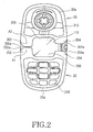
- an icon indicating signal strength For example, an icon indicating signal strength, an icon indicating remaining battery power, an icon indicating message arrival, date, time, and day are displayed on the middle display section 112, which is illustrated in FIGS. 1 and 2.
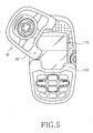
- input data is displayed on the middle display section 112 and the second display section 110, which is illustrated in FIG. 5.
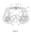
- graphics for games are displayed on the middle display section 112 and the first and second display sections 110 and 114, which is illustrated in FIGS. 3 and 4.
- the first key swing housing 20 includes a first opening 206 for constantly exposing the middle display section 112 of the display unit, and a pair of first protruded parts 202 and 204, which are disposed adjacent to the first opening 206 while being opposite to each other.
- the first key swing housing 20 is provided at an upper surface 20a thereof with a first key array 210 comprising a plurality of keys.
- the first key array 210 comprises numeral keys, character keys, and function keys.
- the first key swing housing 20 is provided at a predetermined position of the lower end thereof with a microphone 212.
- the second key swing housing 30 includes a second opening 306 for constantly exposing the middle display section 112 of the display unit, and a pair of second protruded parts 302 and 304, which are disposed adjacent to the second opening 306 while being opposite to each other.
- the second key swing housing 30 is provided at an upper surface 30a thereof with a second key array 310 comprising a plurality of keys.
- the second key array 310 comprises a communication key, menu keys, and a confirmation key.
- the first protruded parts 202 and 204 and the second protruded parts 302 and 304 extend toward each other while being symmetrical to each other, respectively.
- the first protruded parts 202 and 204 have outer round edges 202a and 204a, respectively.
- the second protruded parts 302 and 304 have outer round edges 302a and 304a, respectively. Consequently, interference between the first protruded parts 202 and 204 and the second protruded parts 302 and 304 is effectively prevented when the first and second key swing housing 20 and 30 are rotated.
- the first and second openings 206 and 306 communicate with each other with the result that the middle display section 112 of the display unit is constantly exposed and not obstructed.
- the first and second hinge axes A1 and A2 are spaced apart from each other while being in parallel with each other. Specifically, the first hinge axis A1 is located adjacent to the middle display section 112 of the display unit, and the second hinge axis A2 is also located adjacent to the middle display section 112 of the display unit. The first hinge axes A1 and A2 are located adjacent to each other. Especially, the first and second hinge axes A1 and A2 are disposed on one side of the display unit, on the other side of which is disposed the camera lens module 40.
- the first and second hinge axes A1 and A2 are located adjacent to the middle part of the lateral side 113 of the display unit, respectively.
- the first hinge axis A1 extends through one of the first protruded parts, i.e., the first protruded part 202
- the second hinge axis A2 extends through one of the second protruded parts, i.e., the second protruded part 302.
- the first and second hinge axes A1 and A2 vertically extend from the upper surface 10a of the body housing 10, respectively.
- the first and second hinge axes A1 and A2 are perpendicular to the hinge axis of the camera lens module 40, respectively.
- FIGS. 1 and 2 show the portable swing-type communication device in the phone mode
- FIGS. 3 and 4 show the portable swing-type communication device in the game mode.
- the first and second key swing housings 20 and 30 are fully rotated about the first and second hinge axes A1 and A2, respectively, such that the key-pushing operation can be conveniently performed on the portable swing-type communication device with a user using both hands.
- FIG. 5 shows the portable swing-type communication device in the text transmission mode.
- the second key swing housing 30 is rotated at predetermined degrees about the second hinge axis A2 such that the key-pushing operation can be conveniently performed on the portable swing-type communication device.
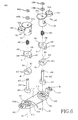
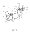
- FIGS. 6 and 7 respectively show a hinge apparatus 400 that rotatably connects the first and second key swing housings 20 and 30 to the body housing 10, and FIGS. 8 to 11 respectively show the operation of the first and second key swing housings 20 and 30 connected to the body housing 10 by means of the hinge apparatus 400.
- the hinge apparatus 400 comprises a hinge base 401, hinge housings 402, and supporting shafts 403.
- a hinge cam 404 In each of the hinge housings 401 is accommodated a hinge cam 404, a hinge shaft 405, and a coil spring 447.
- the hinge base 401 is securely fixed to the inner surface of the body housing 10. Specifically, the hinge base 401 is disposed adjacent to the middle region of the lateral side 113 of the display unit 110, 112, and 114.
- the hinge base 401 has a base plate 411, which is opposite to the inner surface of the body housing 10.
- the base plate 411 is provided at both ends of the upper surface thereof with rotating grooves 413, each of which is depressed a predetermined depth.
- Each of the rotating grooves 413 is formed as a fixing groove, which is depressed a predetermined depth from the bottom surface of the corresponding rotating groove 413.
- the supporting shafts 403 are securely fixed in the fixing grooves 414, respectively.
- the lower ends of the hinge housings 402 are rotatably located in the rotating grooves 413, respectively.
- the rotating grooves 413 are disposed on the first and second hinge axes A1 and A2, respectively.
- At both ends of the base plate 411 are integrally formed connection pieces 412, respectively.
- Each of the connection pieces 412 has a connection hole 412a formed therethrough in the longitudinal direction of the corresponding hinge housing 402.
- the hinge base 401 is securely fixed to the inner surface of the body housing 10 through engagement of screws (not shown) into the connection holes 412a.
- Each of the hinge housings 402 comprises a cylindrical body 421 extending in the direction of the corresponding one of the first and second hinge axes A1 and A2, and a connection piece 423 integrally formed at a predetermined position of the outer circumference of the cylindrical body 421.
- the lower ends of the hinge housings 402 are rotatably located in the rotating grooves 413 of the hinge base 401.
- the hinge housings 402 are fixed to the first and second key swing housings 20 and 30, respectively.
- Each of the connection pieces 423 has a connection hole 423a formed therethrough in the longitudinal direction of the corresponding hinge housing 402 so that the hinge housings 402 can be fixed to the first and second key swing housings 20 and 30, respectively.
- the lower ends of the hinge housings 402 are fully open, and the upper ends of the hinge housings 402 are closed. At the upper closed ends of the hinge housings 402 are formed through-holes 421 a, respectively.
- the coil springs 447, the hinge cams 404, and the hinge shafts 405 are accommodated, in turn, in the hinge housings 402 through the lower open ends of the hinge housings 402, respectively.
- Resilient forces from the coil springs 447 are applied to the hinge cams 404 such that the hinge cams 404 are pressed against the hinge shafts 405, respectively.
- Each of the hinge cams 404 is provided at the opposite sides of the outer circumference thereof with sliding protrusions 443.
- Each of the hinge housings 402 is provided at the inner circumference thereof with sliding grooves (not shown) corresponding to the sliding protrusions 443, respectively.
- the sliding grooves extend in the longitudinal direction of the corresponding hinge housings 402. Consequently, the hinge cams 404 can be reciprocated in the hinge housings 402 and can also be rotated along with the hinge housings 402, respectively.
- Each of the hinge cams 404 is provided at the lower end thereof opposite to the corresponding hinge shaft 405 with a valley part 441.
- the hinge shafts 405 are rotatably accommodated in the hinge housings 402 while being fitted on the supporting shafts 403, respectively. Consequently, the hinge shafts 405 are rotated in the hinge housings 402, respectively. Specifically, the hinge housings 402 are rotated relative to the hinge base 401 while the hinge shafts 405 are fixed to the supporting shafts 403, which are also fixed to the hinge base 410. Consequently, the hinge shafts 405 are rotated relative to the hinge housings 402, respectively, with the result that the hinge shafts 405 are rotated while tightly contacting the hinge cams 404, respectively.
- Each of the hinge shafts 405 is provided at the upper end thereof opposite to the corresponding hinge cam 404 with a crest part 451. Consequently, the hinge cams 404 are rectilinearly moved in the hinge housings 402, respectively, as the hinge shafts 405 are rotated.
- the valley parts 441 of the hinge cams 404 are selectively engaged with the crest parts 451 of the hinge shafts 405, respectively.
- the hinge cams 404 are pressed against the hinge shafts 405 by means of the coil springs 447, and thus the valley parts 441 of the hinge cams 404 are engaged with the corresponding crest parts 451 of the hinge shafts 405 when the hinge shafts 405 are rotated.
- Each of the supporting shafts 403 is provided at the lower end thereof with a fixing body 432 having a shape corresponding to that of each of the fixing grooves 414.
- Each of the supporting shafts 403 is also provided at the outer circumference of the upper end thereof with a connection groove 432.
- the upper ends of the supporting shafts 403 are inserted through the through-holes 421a formed at the upper closed ends of the hinge housings 402.
- In the connection grooves 432 of the upper ends of the supporting shafts 403 protruded from the hinge housings 402 through the through-holes 421a are fitted E-rings 439a, respectively. Between the E-rings 439a and the hinge housings 402 may be disposed washers 439b, respectively. As shown in FIG.
- the supporting shafts 403 are securely connected to the fixing grooves 414 of the hinge base 401 through the engagement of screws (not shown) in connecting holes 415 formed at the fixing grooves 414, respectively, although the supporting shafts 403 may be integrally formed with the hinge base 401. It can be easily appreciated by those skilled in the art that the supporting shafts 403 can be integrally formed with the hinge base 401, since the supporting shafts 403 and the hinge shafts 405 are securely fixed on the hinge base 401.
- Each of the hinge cams 404 has a through-hole 449, through which the corresponding supporting shaft 403 is inserted, and each of the hinge shafts 405 has a through-hole 459, through which the corresponding supporting shaft 403 is also inserted. Consequently, the supporting shafts 430 are inserted through the hinge housings 402 and are then protruded from the hinge housings 402 through the through-holes 421 a, respectively.
- FIGS. 8 to 11 show the hinge apparatus 400 mounted to the portable swing-type communication device. It should be noted that assembly of the hinge apparatus 400 to the portable swing-type communication device will be described below with reference to FIGS. 8 to 11 while the body housing 10 of the portable swing-type communication device is not shown in the drawings.
- the hinge base 401 is attached to the inner surface of the body housing 10 of the portable swing-type communication device.
- the hinge housings 402 are attached to the inner surfaces of the first and second protruded parts 202 and 302 of the first and second key swing housings 20 and 30, respectively.
- the hinge housings 402 extend downward from the first and second key swing housings 20 and 30, respectively, and are then rotatably connected to the hinge base 401 attached to the inner surface of the body housing 10.
- the inner circumferences of the hinge holes formed at the first and second key swing housings 20 and 30, through which the hinge housings 402 are inserted, respectively, are spaced apart from the outer circumferences of the hinge housings 402, respectively, such that flexible printed circuits 409 (Refer to FIG. 11) to connect circuit devices mounted in the body housing 10 and the first and second key swing housings 20 and 30 are disposed therebetween.
- the inner circumferences of the hinge holes formed at the body housing 10, through which the hinge housings 402 are inserted, respectively are also spaced apart from the outer circumferences of the hinge housings 402, respectively.
- the first and second key swing housings 20 and 30 connected to the body housing 10 by means of the hinge apparatus 400 are placed on the body housing 10 while the first and second key swing housings 20 and 30 are fully opposite to the body housing 10 or rotated to predetermined positions thereof through the cooperation of the hinge cams 404 and the hinge shafts 405 accommodated in the hinge housings 402, respectively.
- the guide protrusions 461 are disposed in the guide slits 406, respectively, which guarantees stability of rotation of the first and second key swing housings 20 and 30.
- the guide slits 406 are spaced a predetermined distance from the hinge housings 403 attached to the first and second key swing housings 20 and 30, and preferably extend in a curved line. As the first and second key swing housings 20 and 30 are rotated, the guide protrusions 461 are slid along the guide slits 406, respectively.
- the guide slits 406 extend from the first and second protruded parts 204 and 304 along the edges of the first and second key swing housings 20 and 30 in the circumferential directions of imaginary circles drawn about the hinge housings 402 attached to the first and second key swing housings 20 and 30.
- the angular distance of each of the guide slits 406 is limited to less than 90 degrees.
- the range of rotation of the first and second key swing housings 20 and 30 is limited by the guide slits 406 and the guide protrusions 461.
- the guide slits 406 formed at the bottom surface of the first and second key swing housings 20 and 30 are exposed.
- the insides of the first and second key swing housings 20 and 30 are also exposed through the guide slits 406.
- the guide slits are covered by means of slit covers 463 (Refer to FIG. 10), by which foreign matter is prevented from being introduced into the first and second key swing housings 20 and 30.
- the guide protrusions 461 are disposed adjacent to both ends of the body housing 10, respectively. When the first and second key swing housings 20 and 30 are fully placed on the body housing 10, the guide protrusions 461 are located at the ends of the first and second key swing housings 20 and 30, respectively. When the first and second key swing housings 20 and 30 are fully rotated from the body housing 10 such that the key-pushing operation can be easily performed with both hands, the guide protrusions 461 are located at the first and second protruded parts 204 and 304 of the first and second key swing housings 20 and 30, respectively.
- the rotary force of the hinge apparatus 400 is applied to the first and second key swing housings 20 and 30 such that the first and second key swing housings 20 and 30 are fully placed on the body housing 10 or the first and second key swing housings 20 and 30 are placed away from the body housing 10 depending upon to what degree the first and second key swing housings 20 and 30 are rotated from the body housing 10.
- the rotary force of the hinge apparatus 400 is still applied to the first and second key swing housings 20 and 30, and the guide protrusions 461 contact one ends of the guide slits 406, respectively. Consequently, it is maintained that the first and second key swing housings 20 and 30 are fully placed on the body housing 10.
- the rotary force of the hinge apparatus 400 is still applied to the first and second key swing housings 20 and 30, and the guide protrusions 461 contact the other ends of the guide slits 406, respectively. Consequently, it is maintained that the first and second key swing housings 20 and 30 are fully rotated from the body housing 10.
- the present invention provides a portable swing-type communication device comprising a body housing and two key swing housings rotatably attached to the body housing while the key swing housings are opposite to the body housing such that the key swing housings are rotated apart from or toward each other, whereby a key-pushing operation is conveniently performed and optimum display sections are provided in any one of modes, i.e., a phone mode, a game mode, or a text transmission mode. Consequently, the portable swing-type communication device of the present invention is very convenient to use.
Landscapes
- Engineering & Computer Science (AREA)
- Signal Processing (AREA)
- Telephone Set Structure (AREA)
Applications Claiming Priority (4)
| Application Number | Priority Date | Filing Date | Title |
|---|---|---|---|
| KR2004012564 | 2004-02-25 | ||
| KR20040012564 | 2004-02-25 | ||
| KR1020040052995A KR100681089B1 (ko) | 2004-02-25 | 2004-07-08 | 스윙 타입 게임용 휴대 통신 장치 및 그의 힌지 장치 |
| KR2004052995 | 2004-07-08 |
Publications (1)
| Publication Number | Publication Date |
|---|---|
| EP1569420A2 true EP1569420A2 (de) | 2005-08-31 |
Family
ID=34752259
Family Applications (1)
| Application Number | Title | Priority Date | Filing Date |
|---|---|---|---|
| EP05003072A Withdrawn EP1569420A2 (de) | 2004-02-25 | 2005-02-14 | Gelenk für geteilte Tastaturen für ein tragbares Kommunikations- und Spielgerät |
Country Status (3)
| Country | Link |
|---|---|
| US (1) | US20050187024A1 (de) |
| EP (1) | EP1569420A2 (de) |
| CN (1) | CN100373971C (de) |
Cited By (3)
| Publication number | Priority date | Publication date | Assignee | Title |
|---|---|---|---|---|
| EP2159998A1 (de) * | 2008-09-02 | 2010-03-03 | LG Electronics | Tragbares Endgerät mit berührungsempfindlichen Benutzeroberflächen |
| EP2442536A1 (de) * | 2010-10-15 | 2012-04-18 | Research In Motion Limited | Mobile Vorrichtung mit drehbarem Teil für Eingabemechanismen |
| WO2020070783A1 (ja) * | 2018-10-02 | 2020-04-09 | 株式会社マーベラス | ゲーム装置 |
Families Citing this family (13)
| Publication number | Priority date | Publication date | Assignee | Title |
|---|---|---|---|---|
| US8382567B2 (en) | 2004-11-03 | 2013-02-26 | Mattel, Inc. | Interactive DVD gaming systems |
| KR100617673B1 (ko) * | 2004-12-06 | 2006-08-28 | 삼성전자주식회사 | 슬라이딩 타입 휴대 단말기의 슬라이딩 모듈 및 이를채용하는 슬라이딩 타입 휴대 단말기 |
| US20060148517A1 (en) * | 2004-12-30 | 2006-07-06 | Lg Electronics Inc. | Video conference feature for a mobile communication terminal |
| US20060287028A1 (en) * | 2005-05-23 | 2006-12-21 | Maciver Peter | Remote game device for dvd gaming systems |
| US7985137B1 (en) | 2005-07-13 | 2011-07-26 | Klitsner Industrial Design, Inc | Hand-held electronic game device |
| US20080004113A1 (en) * | 2006-06-30 | 2008-01-03 | Jason Avery | Enhanced controller with modifiable functionality |
| KR20080090666A (ko) * | 2007-04-05 | 2008-10-09 | 삼성전자주식회사 | 폴딩형 멀티 디스플레이 장치 |
| TWI353552B (en) * | 2007-10-25 | 2011-12-01 | Htc Corp | Electronic device and application program switchin |
| CN201260280Y (zh) * | 2008-08-01 | 2009-06-17 | 鸿富锦精密工业(深圳)有限公司 | 滑动翻盖式电子装置 |
| CN201278621Y (zh) * | 2008-08-29 | 2009-07-22 | 鸿富锦精密工业(深圳)有限公司 | 滑动翻盖式电子装置 |
| CN201297335Y (zh) * | 2008-09-09 | 2009-08-26 | 鸿富锦精密工业(深圳)有限公司 | 枢纽器 |
| CN102086902A (zh) * | 2009-12-02 | 2011-06-08 | 鸿富锦精密工业(深圳)有限公司 | 铰链及使用该铰链的电子设备 |
| CN104680938A (zh) * | 2013-12-03 | 2015-06-03 | 苏州炘知惠信息科技有限公司 | 具有新型按键结构的显示装置 |
Family Cites Families (12)
| Publication number | Priority date | Publication date | Assignee | Title |
|---|---|---|---|---|
| JP2000253113A (ja) * | 1999-02-26 | 2000-09-14 | Hitachi Ltd | 情報通信端末装置 |
| CN2398776Y (zh) * | 1999-08-10 | 2000-09-27 | 敖爱东 | 带侧向旋移开式盖板的手机 |
| JP2001237932A (ja) * | 2000-02-21 | 2001-08-31 | Nec Corp | 携帯端末装置および無線通信端末装置 |
| JP2002281142A (ja) * | 2001-03-19 | 2002-09-27 | Matsushita Electric Ind Co Ltd | カメラ機能付き携帯端末装置 |
| KR100486611B1 (ko) * | 2001-12-18 | 2005-05-03 | 주식회사 팬택앤큐리텔 | 회전가능한 액정표시장치를 가지는 이동통신 단말기 |
| JP2003258970A (ja) * | 2001-12-28 | 2003-09-12 | Matsushita Electric Ind Co Ltd | 携帯端末装置 |
| JP2003239943A (ja) * | 2002-02-18 | 2003-08-27 | Strawberry Corporation | 携帯電話,モバイル等の電子機器並びにヒンジ装置 |
| AU2003210019A1 (en) * | 2002-03-02 | 2003-09-16 | M2Sys Co., Ltd. | Rotary hinge mechanism of portable phone |
| JP4063571B2 (ja) * | 2002-04-10 | 2008-03-19 | 日本電気株式会社 | 折り畳み式携帯通信端末 |
| TW560783U (en) * | 2002-06-24 | 2003-11-01 | Benq Corp | Portable communication apparatus |
| JP3849623B2 (ja) * | 2002-09-05 | 2006-11-22 | 日本電気株式会社 | 携帯通信機器 |
| JP3961397B2 (ja) * | 2002-10-29 | 2007-08-22 | 京セラ株式会社 | 携帯端末装置 |
-
2004
- 2004-10-08 US US10/960,031 patent/US20050187024A1/en not_active Abandoned
- 2004-12-10 CN CNB2004101000895A patent/CN100373971C/zh not_active Expired - Fee Related
-
2005
- 2005-02-14 EP EP05003072A patent/EP1569420A2/de not_active Withdrawn
Cited By (4)
| Publication number | Priority date | Publication date | Assignee | Title |
|---|---|---|---|---|
| EP2159998A1 (de) * | 2008-09-02 | 2010-03-03 | LG Electronics | Tragbares Endgerät mit berührungsempfindlichen Benutzeroberflächen |
| US8364208B2 (en) | 2008-09-02 | 2013-01-29 | Lg Electronics Inc. | Portable terminal having touch sensitive user interfaces |
| EP2442536A1 (de) * | 2010-10-15 | 2012-04-18 | Research In Motion Limited | Mobile Vorrichtung mit drehbarem Teil für Eingabemechanismen |
| WO2020070783A1 (ja) * | 2018-10-02 | 2020-04-09 | 株式会社マーベラス | ゲーム装置 |
Also Published As
| Publication number | Publication date |
|---|---|
| CN100373971C (zh) | 2008-03-05 |
| US20050187024A1 (en) | 2005-08-25 |
| CN1661926A (zh) | 2005-08-31 |
Similar Documents
| Publication | Publication Date | Title |
|---|---|---|
| US7526325B2 (en) | Triple-axis rotation folder-type portable apparatus | |
| KR100630024B1 (ko) | 회전성 디스플레이 장치를 구비한 휴대용 통신 장치 및그의 힌지 장치 | |
| US7522946B2 (en) | Hinge apparatus for mobile communication terminals | |
| EP1569420A2 (de) | Gelenk für geteilte Tastaturen für ein tragbares Kommunikations- und Spielgerät | |
| US20050245297A1 (en) | Portable communication device with sliding and pop-up type keypads | |
| KR100630139B1 (ko) | 이축 힌지 장치를 구비하는 휴대용 단말기 | |
| US7610067B2 (en) | Swing hinge module for portable communication device | |
| US8032192B2 (en) | Portable terminal and sliding/swing-type cradling apparatus thereof | |
| US20050020327A1 (en) | Speaker-up type portable terminal | |
| US20080009330A1 (en) | Dual axis rotation type portable communication terminal and method for controlling the same | |
| JP2002158758A (ja) | 開閉型携帯情報端末 | |
| KR100640395B1 (ko) | 휴대 단말기의 이축 힌지 장치 및 그의 장착 메카니즘 | |
| KR100493102B1 (ko) | 서브 하우징 스토퍼를 구비하는 휴대용 단말기의 힌지 장치 | |
| US20070087596A1 (en) | Portable terminal and sliding type cradle | |
| US7657027B2 (en) | Portable terminal with hinge apparatus | |
| US7440784B2 (en) | Portable communication apparatus | |
| KR100689532B1 (ko) | 휴대용 단말기의 이축 힌지 장치 | |
| KR100681089B1 (ko) | 스윙 타입 게임용 휴대 통신 장치 및 그의 힌지 장치 | |
| EP1511312B1 (de) | Kameralinsenbaugruppe für ein tragbares Endgerät | |
| KR100557065B1 (ko) | 회전성 카메라 렌즈 하우징을 구비한 휴대용 단말기 | |
| KR100663485B1 (ko) | 휴대용 단말기의 힌지 장치 | |
| KR100690717B1 (ko) | 슬라이드형 이동통신 단말기의 회전 가능한 슬라이딩 장치 | |
| US8009064B2 (en) | Data input device for portable terminal | |
| KR100663484B1 (ko) | 자기 거치 기능을 가지는 휴대 단말기 | |
| KR100658207B1 (ko) | 개인휴대단말기 |
Legal Events
| Date | Code | Title | Description |
|---|---|---|---|
| PUAI | Public reference made under article 153(3) epc to a published international application that has entered the european phase |
Free format text: ORIGINAL CODE: 0009012 |
|
| 17P | Request for examination filed |
Effective date: 20050214 |
|
| AK | Designated contracting states |
Kind code of ref document: A2 Designated state(s): AT BE BG CH CY CZ DE DK EE ES FI FR GB GR HU IE IS IT LI LT LU MC NL PL PT RO SE SI SK TR |
|
| AX | Request for extension of the european patent |
Extension state: AL BA HR LV MK YU |
|
| STAA | Information on the status of an ep patent application or granted ep patent |
Free format text: STATUS: THE APPLICATION HAS BEEN WITHDRAWN |
|
| 18W | Application withdrawn |
Effective date: 20080918 |