EP1569313A1 - High Voltage apparatus with particle trap - Google Patents
High Voltage apparatus with particle trap Download PDFInfo
- Publication number
- EP1569313A1 EP1569313A1 EP04405115A EP04405115A EP1569313A1 EP 1569313 A1 EP1569313 A1 EP 1569313A1 EP 04405115 A EP04405115 A EP 04405115A EP 04405115 A EP04405115 A EP 04405115A EP 1569313 A1 EP1569313 A1 EP 1569313A1
- Authority
- EP
- European Patent Office
- Prior art keywords
- switching device
- voltage switching
- particle trap
- installation position
- trap
- Prior art date
- Legal status (The legal status is an assumption and is not a legal conclusion. Google has not performed a legal analysis and makes no representation as to the accuracy of the status listed.)
- Granted
Links
- 239000002245 particle Substances 0.000 title claims abstract description 99
- 238000009434 installation Methods 0.000 claims abstract description 25
- 238000005538 encapsulation Methods 0.000 claims abstract description 17
- 238000000926 separation method Methods 0.000 claims description 21
- 239000012212 insulator Substances 0.000 claims description 16
- 241000722921 Tulipa gesneriana Species 0.000 claims description 12
- 238000000034 method Methods 0.000 claims description 5
- 230000002452 interceptive effect Effects 0.000 abstract description 4
- 230000003287 optical effect Effects 0.000 abstract description 4
- 241000881711 Acipenser sturio Species 0.000 description 10
- 230000005684 electric field Effects 0.000 description 7
- 239000002184 metal Substances 0.000 description 3
- 230000000007 visual effect Effects 0.000 description 3
- 238000005299 abrasion Methods 0.000 description 2
- 101100204059 Caenorhabditis elegans trap-2 gene Proteins 0.000 description 1
- 230000004888 barrier function Effects 0.000 description 1
- 230000007423 decrease Effects 0.000 description 1
- 230000001419 dependent effect Effects 0.000 description 1
- 230000009977 dual effect Effects 0.000 description 1
- 238000010292 electrical insulation Methods 0.000 description 1
- 230000000670 limiting effect Effects 0.000 description 1
- 238000012423 maintenance Methods 0.000 description 1
- 238000004519 manufacturing process Methods 0.000 description 1
- 238000005192 partition Methods 0.000 description 1
- 239000011253 protective coating Substances 0.000 description 1
- 238000010791 quenching Methods 0.000 description 1
- 230000000171 quenching effect Effects 0.000 description 1
- 230000002792 vascular Effects 0.000 description 1
Images

Classifications
-
- H—ELECTRICITY
- H01—ELECTRIC ELEMENTS
- H01H—ELECTRIC SWITCHES; RELAYS; SELECTORS; EMERGENCY PROTECTIVE DEVICES
- H01H33/00—High-tension or heavy-current switches with arc-extinguishing or arc-preventing means
- H01H33/02—Details
- H01H33/24—Means for preventing discharge to non-current-carrying parts, e.g. using corona ring
- H01H33/245—Means for preventing discharge to non-current-carrying parts, e.g. using corona ring using movable field electrodes
-
- H—ELECTRICITY
- H02—GENERATION; CONVERSION OR DISTRIBUTION OF ELECTRIC POWER
- H02B—BOARDS, SUBSTATIONS OR SWITCHING ARRANGEMENTS FOR THE SUPPLY OR DISTRIBUTION OF ELECTRIC POWER
- H02B1/00—Frameworks, boards, panels, desks, casings; Details of substations or switching arrangements
- H02B1/015—Boards, panels, desks; Parts thereof or accessories therefor
- H02B1/04—Mounting thereon of switches or of other devices in general, the switch or device having, or being without, casing
-
- H—ELECTRICITY
- H01—ELECTRIC ELEMENTS
- H01H—ELECTRIC SWITCHES; RELAYS; SELECTORS; EMERGENCY PROTECTIVE DEVICES
- H01H9/00—Details of switching devices, not covered by groups H01H1/00 - H01H7/00
- H01H9/02—Bases, casings, or covers
- H01H2009/0292—Transparent window or opening, e.g. for allowing visual inspection of contact position or contact condition
-
- H—ELECTRICITY
- H01—ELECTRIC ELEMENTS
- H01H—ELECTRIC SWITCHES; RELAYS; SELECTORS; EMERGENCY PROTECTIVE DEVICES
- H01H33/00—High-tension or heavy-current switches with arc-extinguishing or arc-preventing means
- H01H33/02—Details
- H01H33/53—Cases; Reservoirs, tanks, piping or valves, for arc-extinguishing fluid; Accessories therefor, e.g. safety arrangements, pressure relief devices
- H01H33/56—Gas reservoirs
Definitions
- the invention relates to the field of high voltage switch technology. It refers to a high voltage switching device and a Method for separating interference particles in a high-voltage switching device according to the preamble of the independent claims and on a high voltage system according to claim 10.
- Such a high voltage switching device is for example off DE 41 20 309 known.
- a particle trap which as a formed by a cover closed neck, the inside provided with a protective coating.
- Such a particle trap is provided for use in high-voltage switching devices which have a grounded, metallic encapsulation, which is a voltage-loaded Active part encloses. Interference particles that are inside the encapsulation and reduce the dielectric strength of the high voltage switching device should be able to accumulate within the particle trap. The like separated Störp personality should remain within the particle trap, so that a not by these sturgeon particles lowered, sufficiently high given dielectric strength of the high voltage switching device.
- Such a high voltage switching device has the disadvantage that its dielectric strength during operation and thus its Operational safety is not well ensured.
- a high-voltage switching device is to be created be, which has a high reliability.
- the inventive high-voltage switching device which in at least one Installation position is usable and has a metallic encapsulation, including a switching path and a particle trap for receiving Störpenien, characterized in that in the at least one Installation position, the particulate trap vertically below the switching path is.
- a High voltage switching device may include electrically conductive and non-conductive particles.
- Such particles are formed, for example the manufacture of the high voltage switching device and must before the Closing and use of the high-voltage switching device so completely as possible to be removed from the interior of the enclosure. Also at each opening and closing of the high voltage switching device can Ingress of foreign particles. In particular, however, interfering particles can also occur during operation of the high voltage switching device.
- a high voltage switching device at least one movable contact piece having a releasable contact with a forms another contact piece. By the movement of the movable Contact pieces can be generated by abrasion particles.
- the generated interference particles move preferably downwards (especially when switched off) and thus preferably land vertically below the switching path.
- a there arranged particulate trap these sturgeon particles (and thus particularly many sturgeon particles) and thus the reliability of the Increase high voltage switching device.
- Such a high voltage switching device can be used in a or be provided in several mounting positions. Where the particle trap According to arrange according to the invention, thus depends on the one or the Mounting positions.
- a particle trap advantageously always contains a dielectric such little charged area that contains the particulate trap during operation of the high voltage switching device can not leave.
- the particle trap is vascular shaped, so that leaving the Particle trap during the operation of the Hochhardsschalttechniks_ In the Sturgeon particles is difficult.
- a particulate trap includes one Metallically surrounded area with a depression.
- the electric field strength in the particle trap should be around two typically Magnitudes, advantageously three or more orders of magnitude, less be as the electric field strength in dielectric heavily loaded areas within the enclosure. This ensures a secure separation of Noise particles, even during switching operations.
- the electric field strength in the particle trap less than 10 kV / cm.
- the particulate trap includes a Viewing window.
- the viewing window can be a visual check of the Presence, type and amount of sturgeon particles during the Allow operation. This optical test can be used to to detect or to identify the need for maintenance or revision confirm without the encapsulation of the high voltage switching device must be opened.
- the high-voltage switching device is in usable at least a second mounting position and has a second Particle trap, wherein in the at least one second mounting position the second particulate trap is arranged vertically below the switching path.
- the second particulate trap may also be vertically below another Switching be angordnet, and in particular can also for each Switching path and each mounting position to be provided in each case a particle trap, which can be partly identical.
- the tulip of the Fixed contact naturally connects directly to the switching path, so that particles generated there are caught at the place where they are arise.
- the contact tulip forms a Faraday cage, so that the Surrounded by the contact tulip interior is field-free.
- Such an insulator part may have the task of the active part or parts support thereof and / or the internal volume of the high voltage switching device from the internal volume of an adjacent component to separate.
- Insulator parts in high voltage switching devices are dielectrically high loaded and therefore particularly susceptible to interference.
- An insulator part with an im essentially horizontally oriented, the switchgear interior facing surface is particularly susceptible to spurious particles, which are arranged on the surface.
- a metallic wall or an electrically conductive elevation between the Insulator part and the particle trap can prevent one hand Particle trap side landing sturgeon particles towards insulator part move, and on the other hand for a low electric field strength in the area the particle trap provide.
- the high-voltage switching device a separator, in particular a separator with a contact tube as movable contact and advantageous with a visible separation distance as Switching path.
- the high voltage switching device can also be an earth electrode or a to act as a technological isolator, whose earth-separating line the Switching path represents. This is particularly advantageous High-voltage switchgear a isolator earth electrode with one earth-side and one earth-fault high-voltage side separation line.
- the opening essentially form the inside of a Faraday cage, leaving the opening is field-free.
- a viewing window of the particle trap at the same time as a Viewing window for visual accessibility of a visible Be separating line.
- the viewing window has the functions, on the one hand the visible separation section and on the other hand the particle trap respectively, to make the stubborn particles therein optically accessible.
- This dual function of the viewing window becomes a simplified structure reached the high voltage switching device.
- a visible separation distance is at one for the particle assessment advantageous horizontal orientation of the viewing window the disadvantage of a generally poorer accessibility of the viewing window for a through the viewing window looking person taken over.
- Such a high voltage switching device is in terms of its usability very flexible, as it has at least three mounting positions, and still is It is very reliable due to the respective particle traps.
- An inventive high voltage switching device can be part of a be inventive high voltage system.
- the inventive method for separating Störp motherboardn in a high-voltage switching device that in at least one installation position is usable and a switching path and a particle trap for recording has the Störp motherboard is characterized in that the Störp motherboard in one in the at least one mounting position vertically below the Switching distance arranged particle trap to be separated.
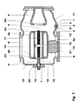
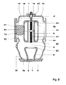
- Fig. 1 shows an inventive earth separator in a first Installation position. This earth-divider is still in at least two more Can be used mounting positions, which in Figs. 2 and 3 are shown.
- the earth separator has a metallic encapsulation 10 which is filled with an insulating gas 12, advantageously SF 6 .
- an insulating gas 12 advantageously SF 6 .
- vacuum could also prevail within the encapsulation 10.
- the encapsulation 10 includes active parts, which are supported on an insulator part 8.
- a connector 15 supported on a metal part 21 (inner armature of the insulator part 8) provided in the insulator part 8 produces an electrical connection of the active part to the outside.
- a contact tube carrier 14, which carries a contact tube 6 which contacts the contact tube carrier 14 by means of a spiral spring contact 20, is supported on the connecting piece 15.
- the contact tube can be moved between three positions.
- another, for example, fully cylindrical trained movable contact piece is conceivable.
- the spindle has an insulating shaft 16.
- a ground-side end 6b of FIG Contact tube 6 is received in an opening 7 and turns over Spiral contacts 20 an electrical connection between the grounded Encapsulation 10 and the Metaillteil 21 ago.
- An earth-side separation section 4 ' is thus bridged while a high-voltage side separation section 4 open is.
- the opening 7 for receiving the contact tube 10 is in Fig. 1 in the Encapsulation integrated; other configurations of the opening 7 are possible.
- the illustrated earth isolator has for its three mounting positions (see Figs. 1, 2, 3) each one vertically below the separator section 4 arranged Particle trap, wherein in Figs. 2 and 3 installation positions shown each one particle trap both vertically below the separator section 4 as well vertically below the separator section 4 'is arranged.
- An additional Particle trap for the earth-side separation section 4 'could for the in Fig. 1 shown installation position are provided (not shown).
- the particulate trap is approximated by a vertically oriented one cylindrical opening in the enclosure 10 and a viewing window 3 is formed.
- the viewing window 3 is advantageously used simultaneously as a viewing window to the optical Making available the optical separation line 4.
- a metallic wall 9 formed by the encapsulation 10 is formed between the particle trap 1 and the horizontally oriented insulator part 8 .
- the Particle trap 1 lies within a bulge 11 of the encapsulation 10. Due to the bulge 11, the electric field strength in the range of Particle trap 1 decreases.
- the bulge 11 and the wall 9 can Alternatively, as components of the particle trap 1 are interpreted.
- Dielectric particularly heavily loaded places in a high voltage switching device are triple points, like the triple point 13, which passes through the insulating part 8, the encapsulation 10 and the insulating gas 12 is formed. There located Noise particles are responsible for the dielectric strength of the high-voltage switching device especially dangerous.
- a wall like the wall 9 in Fig. 1 is therefore with great advantage between the triple point 13 and below the Separating section 4 arranged particle trap 1 is arranged.
- the earth-separator is oriented such that at a Switching the contact tube 6 moves in the horizontal.
- the contact tube 6 is vertical movable.
- the earthing separator is shown in a third mounting position, in which the opening 7 for receiving the contact tube 6 as vertical Particle trap 1 'arranged below the two separating sections 4, 4' serves.
- the opening 7 is formed substantially annular. Since she is in the encapsulation 10 is provided, it provides for Störp sie 2 a metallic environment, so that interfering particles 2 within the particle trap 1 '' exposed only very low field strengths and thus stored safely are.
- the particulate trap 1,1 ', 1' ' centrally below the (respective) Separation path arranged. It can be in the case of a horizontal extending separation line (as in Fig. 1) over the entire length of Extending separation line 4 or have an even greater width or, as shown in Fig. 1, have a smaller width, in the latter case with great advantage a bulge 11 is exhibited, which is in horizontal direction over at least the entire extent of the Isolating section 4 extends.
Landscapes
- Engineering & Computer Science (AREA)
- Power Engineering (AREA)
- Gas-Insulated Switchgears (AREA)
- High-Tension Arc-Extinguishing Switches Without Spraying Means (AREA)
- Electrostatic Separation (AREA)
- Driving Mechanisms And Operating Circuits Of Arc-Extinguishing High-Tension Switches (AREA)
- Image-Pickup Tubes, Image-Amplification Tubes, And Storage Tubes (AREA)
Abstract
Das Hochspannungsschaltgerät ist in mindestens einer Einbaulage
verwendbar und weist eine metallische Kapselung (10) auf. Es beinhaltet eine
Schaltstrecke (4) und eine Partikelfalle (1) zur Aufnahme von Störpartikeln (2)
und ist dadurch gekennzeichnet, dass in der mindestens einen Einbaulage
die Partikelfalle (1) vertikal unterhalb der Schaltstrecke (4) angeordnet ist.
Vorzugsweise weist die Partikelfalle (1) ein Sichtfenster (3) auf. Im Falle eines
Trenners als Hochspannungsschaltgerät kann dieses Sichtfenster (3)
identisch sein mit dem Sichtfenster (3) zur optischen Zugänglichmachung
der sichtbaren Trennstrecke (4) des Trenners. Besonders vorteilhaft ist das
Hochspannungsschaltgerät in mindestens einer zweiten Einbaulage
verwendbar und weist eine zweite Partikelfalle auf, wobei in der mindestens
einen zweiten Einbaulage die zweite Partikelfalle vertikal unterhalb der
Schaltstrecke (4) angeordnet ist. Eine hohe Betriebssicherheit und eine
geringe Störanfälligkeit des Hochspannungsschaltgerätes erreicht.

Description
Die Erfindung bezieht sich auf das Gebiet der Hochspannungsschaltertechnik.
Sie bezieht sich auf ein Hochspannungsschaltgerät und ein
Verfahren zum Separieren von Störpartikeln in einem Hochspannungsschaltgerät
gemäss dem Oberbegriff der unabhängigen Patentansprüche sowie auf
eine Hochspannungsanlage gemäss Anspruch 10.The invention relates to the field of high voltage switch technology.
It refers to a high voltage switching device and a
Method for separating interference particles in a high-voltage switching device
according to the preamble of the independent claims and on
a high voltage system according to
Ein derartiges Hochspannungsschaltgerät ist beispielsweise aus DE 41 20 309 bekannt. Dort ist eine Partikelfalle beschrieben, welche als ein durch einen Deckel geschlossenen Stutzen ausgebildet ist, dessen Innenseite mit einem Schutzbelag versehen ist. Eine solche Partikelfalle ist vorgesehen zum Einsatz in Hochspannungsschaltgeräten, welche eine geerdete, metallische Kapselung aufweisen, welche ein spannungsbeaufschlagtes Aktivteil umschliesst. Störpartikel, die sich innerhalb der Kapselung befinden und die dielektrische Festigkeit des Hochspannungsschaltgeräts reduzieren können, sollen sich innerhalb der Partikelfalle ansammeln. Die derart separierten Störpartikel sollen innerhalb der Partikelfalle verbleiben, so dass eine nicht durch diese Störpartikel erniedrigte, ausreichend hohe dielektrische Festigkeit des Hochspannungsschaltgerätes gegeben ist.Such a high voltage switching device is for example off DE 41 20 309 known. There is described a particle trap, which as a formed by a cover closed neck, the inside provided with a protective coating. Such a particle trap is provided for use in high-voltage switching devices which have a grounded, metallic encapsulation, which is a voltage-loaded Active part encloses. Interference particles that are inside the encapsulation and reduce the dielectric strength of the high voltage switching device should be able to accumulate within the particle trap. The like separated Störpartikel should remain within the particle trap, so that a not by these sturgeon particles lowered, sufficiently high given dielectric strength of the high voltage switching device.
Ein derartiges Hochspannungsschaltgerät hat den Nachteil, dass seine dielektrische Festigkeit während des Betriebes und somit seine Betriebssicherheit nicht gut sichergestellt ist.Such a high voltage switching device has the disadvantage that its dielectric strength during operation and thus its Operational safety is not well ensured.
Es ist deshalb Aufgabe der Erfindung, ein Hochspannungsschaltgerät der eingangs genannten Art zu schaffen, welches die oben genannten Nachteile nicht aufweist. Insbesondere soll ein Hochspannungsschaltgerät geschaffen werden, das eine hohe Betriebssicherheit aufweist.It is therefore an object of the invention to provide a high voltage switching device to create the aforementioned type, which has the disadvantages mentioned above does not have. In particular, a high-voltage switching device is to be created be, which has a high reliability.
Diese Aufgabe löst eine Vorrichtung und ein Verfahren mit den Merkmalen der unabhängigen Patentansprüche.This object is achieved by a device and a method with the features of the independent claims.
Das erfindungsgemässe Hochspannungsschaltgerät, das in mindestens einer Einbaulage verwendbar ist und eine metallische Kapselung aufweist, beinhaltend eine Schaltstrecke und eine Partikelfalle zur Aufnahme von Störpartikeln, kennzeichnet sich dadurch, dass in der mindestens einen Einbaulage die Partikelfalle vertikal unterhalb der Schaltstrecke angeordnet ist.The inventive high-voltage switching device, which in at least one Installation position is usable and has a metallic encapsulation, including a switching path and a particle trap for receiving Störpartikeln, characterized in that in the at least one Installation position, the particulate trap vertically below the switching path is.
Dadurch wird eine geringe Störanfälligkeit und hohe Betriebssicherheit des Hochspannungsschaltgerätes erreicht. Die Wahrscheinlichkeit von Fehlern und Überschlägen ist verringert. This is a low susceptibility and high reliability of High voltage switching device reached. The probability of mistakes and flashovers is reduced.
Zu den Störpartikeln, welche die dielektrische Festigkeit innerhalb eines Hochspannungsschaltgerätes stören können, gehören elektrisch leitfähige und nicht-leitfähige Teilchen. Solche Partikel entstehen beispielsweise bei der Herstellung des Hochspannungsschaltgerätes und müssen vor dem Verschliessen und Gebrauch des Hochspannungsschaltgerätes so vollständig wie möglich aus dem Inneren der Kapselung entfernt werden. Auch bei jedem Öffnen und Schliessen des Hochspannungsschaltgerätes können Störpartikel eindringen. Insbesondere aber können Störpartikel auch während des Betriebes des Hochspannungsschaltgerätes entstehen. Im allgemeinen weist ein Hochspannungsschaltgerät mindestens ein bewegliches Kontaktstück auf, das einen lösbaren Kontakt mit einem weiteren Kontaktstück bildet. Durch die Bewegung des beweglichen Kontaktstücks können durch Abrieb Störpartikel erzeugt werden. Insbesondere entstehen somit an Schaltstrecken besonders viele Störpartikel, welche durch die Reibung zwischen den Kontaktstücken erzeugt werden. An der Schaltstrecke werden auch im Falle von Lichbogenbildung besonders viele Störpartikel erzeugt. Störpartikel können sich bei ausreichend hoher Feldstärke aufgrund von durch das elektrische Feld erzeugten und auf die Störpartikel wirkenden Kräften bewegen und dadurch insbesondere an dielektrisch besonders stark belaseteten Stellen zu Überschlägen führen.To the Störpartikeln, which the dielectric strength within a High voltage switching device may include electrically conductive and non-conductive particles. Such particles are formed, for example the manufacture of the high voltage switching device and must before the Closing and use of the high-voltage switching device so completely as possible to be removed from the interior of the enclosure. Also at each opening and closing of the high voltage switching device can Ingress of foreign particles. In particular, however, interfering particles can also occur during operation of the high voltage switching device. in the Generally, a high voltage switching device at least one movable contact piece having a releasable contact with a forms another contact piece. By the movement of the movable Contact pieces can be generated by abrasion particles. In particular, therefore, particularly many interference particles occur at switching paths, which are generated by the friction between the contact pieces. On The switching path are also in the case of Lichbogenbildung particularly generates many sturgeon particles. Sturgeon particles can become sufficiently high Field strength due to generated by the electric field and on the Move disturbing particles acting forces and thereby in particular Dielectric particularly heavily loaded sites lead to flashovers.
Aufgrund der Gravitation bewegen sich die so erzeugten Störpartikel vorzugsweise abwärts (insbesondere wenn spannungslos geschaltet wird) und landen somit vorzugsweise vertikal unterhalb der Schaltstrecke. Eine dort angeordnete Partikelfalle kann diese Störpartikel (und somit besonders viele Störpartikel) aufnehmen und dadurch die Betriebssicherheit des Hochspannungsschaltgerätes erhöhen.Due to the gravitation, the generated interference particles move preferably downwards (especially when switched off) and thus preferably land vertically below the switching path. A there arranged particulate trap, these sturgeon particles (and thus particularly many sturgeon particles) and thus the reliability of the Increase high voltage switching device.
Zu den Hochspannungsschaltgeräten im Sinne dieser Anmeldung zählen Hochspannungs- und Hochleistungsschalter, Schalter mit oder ohne Lichtbogenlöschung, Trenner, Erder sowie weitere Schaltgeräte aus dem Bereich der Hochspannungtechnik.To the high-voltage switching devices in the sense of this application count High voltage and high power switches, switches with or without Arc quenching, disconnectors, earthing and other switching devices from the Area of high voltage engineering.
Ein solches Hochspannungsschaltgerät kann für die Verwendung in einer oder in mehreren Einbaulagen vorgesehen sein. Wo die Partikelfalle erfindungsgemäss anzuordnen ist, hängt somit von der oder den Einbaulagen ab.Such a high voltage switching device can be used in a or be provided in several mounting positions. Where the particle trap According to arrange according to the invention, thus depends on the one or the Mounting positions.
Eine Partikelfalle beinhaltet vorteilhaft stets einen dielektrisch derart wenig belasteten Bereich, dass Störpartikel die Partikelfalle während des Betriebs des Hochspannungsschaltgerätes nicht mehr verlassen können. Mit Vorteil ist die Partikelfalle gefässförmig ausgebildet, so dass ein Verlassen der Partikelfalle während_des Betriebs des Hochspannungsschaltgerätes_für die Störpartikel erschwert wird. Vorteilhaft beinhaltet eine Partikelfalle einen metallisch umgebenen Bereich mit einer Vertiefung.A particle trap advantageously always contains a dielectric such little charged area that contains the particulate trap during operation of the high voltage switching device can not leave. With advantage the particle trap is vascular shaped, so that leaving the Particle trap during the operation of the Hochspannungsschaltgerätes_für the Sturgeon particles is difficult. Advantageously, a particulate trap includes one Metallically surrounded area with a depression.
Die elektrische Feldstärke in der Partikelfalle sollte um typischerweise zwei Grössenordnungen, vorteilhaft drei oder mehr Grössenordnungen, geringer sein als die elektrische Feldstärke in dielektrisch stark belasteten Bereichen innerhalb der Kapselung. Dies gewährleistet eine sichere Separierung der Störpartikel, auch während Schaltvorgängen. Bevorzugt beträgt die elektrische Feldstärke in der Partikelfalle weniger als 10 kV/cm.The electric field strength in the particle trap should be around two typically Magnitudes, advantageously three or more orders of magnitude, less be as the electric field strength in dielectric heavily loaded areas within the enclosure. This ensures a secure separation of Noise particles, even during switching operations. Preferably, the electric field strength in the particle trap less than 10 kV / cm.
In einer vorteilhaften Ausführungsform beinhaltet die Partikelfalle ein Sichtfenster. Das Sichtfenster kann eine optische Prüfung des Vorhandenseins, der Art und der Menge von Störpartikeln während des Betriebes ermöglichen. Diese optische Prüfung kann dazu verwendet werden, um den Bedarf für eine Wartung oder Revision zu erkennen oder zu bestätigen, ohne dass die Kapselung des Hochspannungsschaltgerätes geöffnet werden muss. In an advantageous embodiment, the particulate trap includes a Viewing window. The viewing window can be a visual check of the Presence, type and amount of sturgeon particles during the Allow operation. This optical test can be used to to detect or to identify the need for maintenance or revision confirm without the encapsulation of the high voltage switching device must be opened.
In einer vorteilhaften Ausführungsform ist das Hochspannungsschaltgerät in mindestens einer zweiten Einbaulage verwendbar und weist eine zweite Partikelfalle auf, wobei in der mindestens einen zweiten Einbaulage die zweite Partikelfalle vertikal unterhalb der Schaltstrecke angeordnet ist.In an advantageous embodiment, the high-voltage switching device is in usable at least a second mounting position and has a second Particle trap, wherein in the at least one second mounting position the second particulate trap is arranged vertically below the switching path.
Dadurch sind eine grössere Flexibilität des Einsatzes des Hochspannungsschaltgerätes und eine grosse Betriebssicherheit auch in der zweiten Einbaulage des Hochspannungsschaltgerätes gegeben.This gives greater flexibility in the use of the High voltage switching device and a high degree of operational reliability in the given second mounting position of the high voltage switching device.
In dem Fall, dass das Hochspannungsschaltgerät mehrere Schaltstrecken aufweist, kann die zweite Partikelfalle auch vertikal unterhalb einer anderen Schaltstrecke angordnet sein, und insbesondere kann auch für jede Schaltstrecke und jede Einbaulage jeweils eine Partikelfalle vorgesehen sein, welche teilweise auch identisch sein können.In the case that the high voltage switching device several switching paths The second particulate trap may also be vertically below another Switching be angordnet, and in particular can also for each Switching path and each mounting position to be provided in each case a particle trap, which can be partly identical.
Vorteilhaft kann eine der Partikelfallen im wesentlichen durch eine Kontakttulpe, insbesondere eine Festkontakttulpe, des Hochspannungsschaltgerätes gebildet sein. Dies ist vorteilhaft, weil die Tulpe des Festkontaktes naturgemäss direkt an die Schaltstrecke anschliesst, so dass dort erzeugte Partikel an dem Ort gefangen werden, an welchem sie entstehen. Zudem bildet die Kontakttulpe einen Faradaykäfig, so dass der von der Kontakttulpe umgebene Innenraum feldfrei ist.Advantageously, one of the particle traps essentially by a Contact tulip, in particular a Festkontakttulpe, the high-voltage switching device be formed. This is advantageous because the tulip of the Fixed contact naturally connects directly to the switching path, so that particles generated there are caught at the place where they are arise. In addition, the contact tulip forms a Faraday cage, so that the Surrounded by the contact tulip interior is field-free.
In einer vorteilhaften Ausführungsform ist in der mindestens einen Einbaulage ein Isolatorteil mit einer im wesentlichen horizontal ausgerichteten und dem Innern des Hochspannungsschaltgerätes zugewandten Oberfläche vorhanden, wobei zwischen dem Isolatorteil und der Partikelfalle ein gegenüber der Partikelfalle erhöhter metallischer Wall angeordnet ist. In an advantageous embodiment is in the at least one Mounting position an insulator part with a substantially horizontal aligned and the interior of the high voltage switching device facing surface, wherein between the insulator part and the particulate trap is a metallic barrier raised to the particle trap is arranged.
Ein solches Isolatorteil kann die Aufgabe haben, den Aktivteil oder Teile davon zu stützen und/oder das Innenvolumen des Hochspannungsschaltgerätes von dem Innenvolumen eines benachbarten Bauteiles zu trennen. Isolatorteile in Hochspannungsschaltgeräten sind dielektrisch hoch belastet und darum besonders störempfindlich. Ein Isolatorteil mit einer im wesentlichen horizontal ausgerichteten, dem Schaltgeräte-Inneren zugewandten Oberfläche ist besonders anfällig gegenüber Störpartikeln, welche auf der Oberfläche angeordnet sind.Such an insulator part may have the task of the active part or parts support thereof and / or the internal volume of the high voltage switching device from the internal volume of an adjacent component to separate. Insulator parts in high voltage switching devices are dielectrically high loaded and therefore particularly susceptible to interference. An insulator part with an im essentially horizontally oriented, the switchgear interior facing surface is particularly susceptible to spurious particles, which are arranged on the surface.
Ein metallischer Wall oder eine elektrisch leitfähige Erhöhung zwischen dem Isolatorteil und der Partikelfalle kann einerseits verhindern, dass partikelfallenseitig landende Störpartikel sich in Richtung Isolatorteil bewegen, und andererseits für eine geringe elektrische Feldstärke im Bereich der Partikelfalle sorgen.A metallic wall or an electrically conductive elevation between the Insulator part and the particle trap can prevent one hand Particle trap side landing sturgeon particles towards insulator part move, and on the other hand for a low electric field strength in the area the particle trap provide.
In einer vorteilhaften Ausführungsform ist das Hochspannungsschaltgerät ein Trenner, insbesondere ein Trenner mit einem Kontaktrohr als beweglicher Kontakt und vorteilhaft mit einer sichtbaren Trennstrecke als Schaltstrecke. Das Hochspannungsschaltgerät kann auch ein Erder oder ein als Erder wirkender Trenner sein, dessen Erder-Trennstrecke die Schaltstrecke darstellt. Besonders vorteilhaft ist das Hochspannungsschaltgerät ein Trenner-Erder mit einer erdseitigen und einer hochspannungsseitigen Trennstrecke.In an advantageous embodiment, the high-voltage switching device a separator, in particular a separator with a contact tube as movable contact and advantageous with a visible separation distance as Switching path. The high voltage switching device can also be an earth electrode or a to act as a groundbreaking isolator, whose earth-separating line the Switching path represents. This is particularly advantageous High-voltage switchgear a isolator earth electrode with one earth-side and one earth-fault high-voltage side separation line.
Vorteilhaft kann die oder eine der Partikelfallen im wesentlichen durch eine Öffnung zur Aufnahme des Kontaktrohres des Trenners oder Erder-Trenners gebildet sein. Das ist vorteilhaft, weil die Öffnung naturgemäss direkt an die Schaltstrecke anschliesst, so dass dort entstehende Partikel gerade an dem Ort gefangen werden, an welchem sie entstehen. Zudem kann die Öffnung im wesentlichen das Innere eines Faradaykäfigs bilden, so dass die Öffnung feldfrei ist.Advantageously, the or one of the particle traps essentially by a Opening for receiving the contact tube of the separator or earthing disconnector be formed. This is advantageous because the opening by nature directly to the Switching connects so that there emerging particles just at the Be caught at the place where they arise. In addition, the opening essentially form the inside of a Faraday cage, leaving the opening is field-free.
Vorteilhaft kann ein Sichtfenster der Partikelfalle gleichzeitig als ein Sichtfenster zur optischen Zugänglichmachung einer sichtbaren Trennstrecke sein. In diesem Falle hat das Sichtfenster die Funktionen, einerseits die sichtbare Trennstrecke und andererseits die Partikelfalle respektive die darin vorhandenen Störpartikel optisch zugänglich zu machen. Durch diese Doppelfunktion des Sichtfensters wird ein vereinfachter Aufbau des Hochspannungsschaltgerätes erreicht. Gegenüber der standardmässigen vertikalen Ausrichtung des Sichtfensters zur optischen Zugänglichmachung einer sichtbaren Trennstrecke wird bei einer für die Partikelbeurteilung vorteilhaften horizontalen Ausrichtung des Sichtfensters der Nachteil einer im allgemeinen schlechteren Zugänglichkeit des Sichtfensters für eine durch das Sichtfenster schauende Person inkaufgenommen.Advantageously, a viewing window of the particle trap at the same time as a Viewing window for visual accessibility of a visible Be separating line. In this case, the viewing window has the functions, on the one hand the visible separation section and on the other hand the particle trap respectively, to make the stubborn particles therein optically accessible. This dual function of the viewing window becomes a simplified structure reached the high voltage switching device. Compared to the standard vertical orientation of the viewing window for visual access a visible separation distance is at one for the particle assessment advantageous horizontal orientation of the viewing window the disadvantage of a generally poorer accessibility of the viewing window for a through the viewing window looking person taken over.
In einer bevorzugten Ausführungsform ist das Hochspannungsschaltgerät ein Trenner-Erder mit einer erdseitigen und einer hochspannungsseitigen Trennstrecke, welcher ein Kontaktrohr aufweist und in mindestens einer ersten und einer zweiten und einer dritten Einbaulage verwendbar ist, wobei
- in der ersten Einbaulage eine erste Partikelfalle, welche ein Sichtfenster beinhaltet, vertikal unterhalb einer der Trennstrecken angeordnet ist,
- in der zweiten Einbaulage eine zweite Partikelfalle, welche im wesentlichen durch eine Festkontakttulpe des Hochspannungsschaltgerätes gebildet ist, vertikal unterhalb einer der Trennstrecken angeordnet ist, und
- in der dritten Einbaulage eine dritte Partikelfalle, welche im wesentlichen durch eine Öffnung zur Aufnahme des Kontaktrohres gebildet ist, vertikal unterhalb einer der Trennstrecken angeordnet ist.
- in the first installation position, a first particle trap, which contains a viewing window, is arranged vertically below one of the separating sections,
- in the second mounting position, a second particle trap, which is formed essentially by a Festkontakttulpe the high-voltage switching device, is arranged vertically below one of the separation sections, and
- in the third installation position, a third particle trap, which is essentially formed by an opening for receiving the contact tube, is arranged vertically below one of the separation sections.
Ein solches Hochspannungsschaltgerät ist bezüglich seiner Verwendbarkeit sehr flexibel, da es mindestens drei Einbaulagen aufweist, und trotzdem ist es sehr betriebssicher durch die jeweiligen Partikelfallen.Such a high voltage switching device is in terms of its usability very flexible, as it has at least three mounting positions, and still is It is very reliable due to the respective particle traps.
Ein erfindungsgemässes Hochspannungsschaltgerät kann Teil einer erfindungsgemässen Hochspannungsanlage sein.An inventive high voltage switching device can be part of a be inventive high voltage system.
Das erfindungsgemässe Verfahren zum Separieren von Störpartikeln in einem Hochspannungsschaltgerät, das in mindestens einer Einbaulage verwendbar ist und eine Schaltstrecke und eine Partikelfalle zur Aufnahme der Störpartikel aufweist, ist dadurch gekennzeichnet, dass die Störpartikel in einer in der mindestens einen Einbaulage vertikal unterhalb der Schaltstrecke angeordneten Partikelfalle separiert werden.The inventive method for separating Störpartikeln in a high-voltage switching device that in at least one installation position is usable and a switching path and a particle trap for recording has the Störpartikel, is characterized in that the Störpartikel in one in the at least one mounting position vertically below the Switching distance arranged particle trap to be separated.
Die weiteren vorteilhaften erfindungsgemässen Verfahren ergeben sich aus den vorteilhaften erfindungsgemässen Vorrichtungen.The further advantageous processes according to the invention result from the advantageous inventive devices.
Weitere bevorzugte Ausführungsformen und Vorteile gehen aus den abhängigen Patentansprüchen und den Figuren hervor.Further preferred embodiments and advantages will be apparent from the dependent claims and the figures.
Im folgenden wird der Erfindungsgegenstand anhand von bevorzugten Ausführungsbeispielen, welche in den beiliegenden Zeichnungen dargestellt sind, näher erläutert. Es zeigen schematisch im Schnitt:
- Fig. 1
- einen erfindungsgemässen Erder-Trenner in einer ersten Einbaulage;
- Fig. 2
- den erfindungsgemässen Erder-Trenner aus Fig. 1 in einer zweiten Einbaulage;
- Fig. 3
- den erfindungsgemässen Erder-Trenner aus Fig. 1 in einer dritten Einbaulage;
- Fig. 1
- an inventive earth separator in a first installation position;
- Fig. 2
- the inventive earth separator of Figure 1 in a second mounting position.
- Fig. 3
- the inventive earth separator of Figure 1 in a third installation position.
Die in den Zeichnungen verwendeten Bezugszeichen und deren Bedeutung sind in der Bezugszeichenliste zusammengefasst aufgelistet. Grundsätzlich sind in den Figuren gleiche oder gleichwirkende Teile mit gleichen Bezugszeichen versehen. Die beschriebenen Ausführungsbeispiele stehen beispielhaft für den Erfindungsgegenstand und haben keine beschränkende Wirkung.The reference numerals used in the drawings and their meaning are listed in the list of references summarized. in principle are in the figures the same or equivalent parts with the same Provided with reference numerals. The described embodiments are exemplary of the subject invention and have no limiting Effect.
Fig. 1 zeigt einen erfindungsgemässen Erder-Trenner in einer ersten Einbaulage. Dieser Erder-Trenner ist noch in mindestens zwei weiteren Einbaulagen einsetzbar, welche in den Figs. 2 und 3 dargestellt sind.Fig. 1 shows an inventive earth separator in a first Installation position. This earth-divider is still in at least two more Can be used mounting positions, which in Figs. 2 and 3 are shown.
Der Erder-Trenner weist eine metallische Kapselung 10 auf, welche mit
einem Isoliergas 12, vorteilhaft SF6, gefüllt ist. Alternativ könnte auch
Vakuum innerhalb der Kapselung 10 herrschen. Weiterhin beinhaltet die
Kapselung 10 Aktivteile, welche auf einem Isolatorteil 8 abgestützt sind. Ein
auf einem in dem Isolatorteil 8 vorgesehenen Metallteil 21 (Innenarmatur des
Isolatorteils 8) abgestütztes Verbindungsstück 15 stellt eine elektrische
Verbindung des Aktivteils nach aussen her. Auf das Verbindungsstück 15
stützt sich ein Kontaktrohrträger 14, welcher ein Kontaktrohr 6 trägt,
welches der Kontaktrohrträger 14 mittels eines Spiralfederkontaktes 20
kontaktiert. Mittels einer mittels einer Spindelführung 18 geführten Spindel
17 und einer Wandermutter 19 kann das Kontaktrohr zwischen drei
Positionen bewegt werden. Anstelle des Kontaktrohres ist auch ein anderer,
beispielsweise vollzylindrisch ausgebildetes bewegliches Kontaktstück
vorstellbar. Zur elektrischen Isolation der Wandermutter 19 gegenüber der
Kapselung 10 weist die Spindel eine Isolierwelle 16 auf.The earth separator has a
In einer Erdungsposition des Erder-Trenners ist ein erdseitiges Ende 6b des
Kontaktrohres 6 in einer Öffnung 7 aufgenommen und stellt über
Spiralkontakte 20 eine elektrische Verbindung zwischen der geerdeten
Kapselung 10 und dem Metaillteil 21 her. Eine erdseitige Trennstrecke 4' ist
somit überbrückt, während eine hochspannungsseitige Trennstrecke 4 offen
ist. Die Öffnung 7 zur Aufnahme des Kontaktrohres 10 ist in Fig. 1 in die
Kapselung integriert; andere Ausbildungen der Öffnung 7 sind möglich.In a grounding position of the earth-separator, a ground-
In einer Hochspannungsposition des Erder-Trenners wird ein Kontakt
zwischen einer hochspannungsbeaufschlagten Kontakttulpe 5 und dem
Metallteil 21 gebildet, indem ein hochspannungsseitiges Ende 6a des
Kontaktrohres 10 die Kontakttulpe 5 mittels Spiralfederkontakten 20
kontaktiert.In a high voltage position of the earth separator becomes a contact
between a
In der in Fig. 1 dargestellten Zwischenposition kontaktiert das Kontaktrohr
10 weder die Erdungs- noch die Hochspannungsseite des Erder-Trenners.In the intermediate position shown in Fig. 1 contacts the
Für weitere Details zum Aufbau und zur Funktion des beschriebenen Erder-Trenners wird auf die am gleichen Tag wie die vorliegende Patentanmeldung beim europäischen Patentamt und mit "Schaltgerät mit Trenn- und/oder Erderfunktion" betitelte Patentanmeldung der Erfinder Daniel Bleiker, Bojan Pavlovic, Diego Sologuren, Walter Holaus und Martin Wieser desselben Anmelders verwiesen. For further details on the structure and function of the described earth isolator will be on the same day as the present patent application at the European Patent Office and with "switching device with separation and / or Erderfunktion "titled patent application of the inventors Daniel Bleiker, Bojan Pavlovic, Diego Sologuren, Walter Holaus and Martin Wieser of the same Referenced.
Der dargestellte Erder-Trenner weist für seine drei Einbaulagen (siehe Figs.
1, 2, 3) jeweils eine vertikal unterhalb der Trennerstrecke 4 angeordnete
Partikelfalle auf, wobei in den in den Figs. 2 und 3 dargestellten Einbaulagen
je eine Partikelfalle sowohl vertikal unterhalb der Trennerstrecke 4 als auch
vertikal unterhalb der Trennerstrecke 4' angeordnet ist. Eine zusätzliche
Partikelfalle für die erdseitige Trennstrecke 4' könnte für die in Fig. 1
dargestellte Einbaulage vorgesehen werden (nicht dargestellt).The illustrated earth isolator has for its three mounting positions (see Figs.
1, 2, 3) each one vertically below the
In Fig. 1 wird die Partikelfalle durch eine vertikal ausgerichtete ungefähr
zylindrische Öffnung in der Kapselung 10 und ein Sichtfenster 3 gebildet.
Das Sichtfenster 3 dient vorteilhaft gleichzeitig als Sichtfenster zur optischen
Zugänglichmachung der optischen Trennstrecke 4. Es sind einige
Störpartikel 2 innerhalb der Partikelfalle 1 und einige Störpartikel 2' nahe
der Partikelfalle 1 dargestellt. Aufgrund der Geometrie der Partikelfalle 1
herrschen innerhalb der Partikelfalle 1 sehr geringe Feldstärken und eine
sehr geringe dielektrische Belastung.In Fig. 1, the particulate trap is approximated by a vertically oriented one
cylindrical opening in the
Zwischen der Partikelfalle 1 und dem horizontal ausgerichteten Isolatorteil 8
ist ein von der Kapselung 10 gebildeter metallischer Wall 9 gebildet. Die
Partikelfalle 1 liegt innerhalb einer Ausbauchung 11 der Kapselung 10.
Durch die Ausbauchung 11 wird die elektrische Feldstärke im Bereich der
Partikelfalle 1 verringert. Durch den Wall 9 wird es Störpartikeln 2' auf der
der Partikelfalle 1 zugewandten Seite des Walles 9 fast unmöglich gemacht
oder zumindest erschwert, in Richtung des Isolierteils 8 zu wandern und auf
eine dem Innern des Erder-Trenners zugewandten Oberfläche 8a des
Isolierteils 8 zu gelangen, so dass also eine hohe Betriebssicherheit des
Erder-Trenners erreicht wird. Die Ausbauchung 11 und der Wall 9 können
alternativ auch als Bestandteile der Partikelfalle 1 interpretiert werden. Between the
Dielektrisch besonders hoch belastete Orte in einem Hochspannungsschaltgerät
sind Tripelpunkte, wie der Tripelpunkt 13, welcher durch das Isolierteil
8, die Kapselung 10 und das Isoliergas 12 gebildet wird. Dort befindliche
Störpartikel sind für die dielektrische Festigkeit des Hochspannungsschaltgerätes
besonders gefährlich. Ein Wall wie der Wall 9 in Fig. 1 ist darum mit
grossem Vorteil zwischen dem Tripelpunkt 13 und der unterhalb der
Trennstrecke 4 angeordneten Partikelfalle 1 angeordnet.Dielectric particularly heavily loaded places in a high voltage switching device
are triple points, like the
In Fig. 1 ist der Erder-Trenner derart ausgerichtet, dass bei einem
Schaltvorgang das Kontaktrohr 6 sich in der Horizontalen bewegt. In den in
den Figs. 2 und 3 dargestellten Einbaulagen ist das Kontaktrohr 6 vertikal
bewegbar.In Fig. 1, the earth-separator is oriented such that at a
Switching the
Als vertikal unterhalb der beiden Trennstrecken 4,4' angeordnete
Partikelfalle 1 ' dient in der in Fig. 2 dargestellten Einbaulage im
wesentlichen die Kontakttulpe 5. Diese stellt ein metallisches Behältnis dar,
in welchem Störpartikel 2 sicher gelagert sind, da das elektrische Feld
innerhalb der Kontakttulpe 5 vernachlässigbar klein ist und die Kontakttulpe
5 gleichzeitig einen hohen, praktisch unüberwindbaren Wall für die
Störpartikel 2 darstellt. Die Kontakttulpe ist auf ihrer Bodenseite geschlossen
und mit einer metallischen Innenarmatur des Isolatorteils verschraubt.As vertically below the two
In Fig. 3 ist der Erder-Trenner in einer dritten Einbaulage dargestellt, in
welcher die Öffnung 7 zur Aufnahme des Kontaktrohres 6 als vertikal
unterhalb der beiden Trennstrecken 4,4' angeordnete Partikelfalle 1''
dient. Die Öffnung 7 ist im wesentlichen ringförmig ausgebildet. Da sie in
der Kapselung 10 vorgesehen ist, bietet sie für Störpartikel 2 eine
metallische Umgebung, so dass Störpartikel 2 innerhalb der Partikelfalle 1''
nur sehr geringen Feldstärken ausgesetzt und somit dort sicher gelagert
sind. In Fig. 3, the earthing separator is shown in a third mounting position, in
which the
Vorteilhaft ist die Partikelfalle 1,1',1'' mittig unterhalb der (jeweiligen)
Trennstrecke angeordnet. Sie kann sich im Falle einer horizontal
verlaufenden Trennstrecke (wie in Fig. 1) über die gesamte Länge der
Trennstrecke 4 erstrecken oder eine noch grössere Breite aufweisen oder,
wie in Fig. 1, eine geringere Breite aufweisen, wobei in letzterem Fall mit
grossem Vorteil eine Ausbauchung 11 aufgewiesen wird, welche sich in
horizontaler Richtung über mindestens die gesamte Erstreckung der
Trennstrecke 4 erstreckt.Advantageously, the
Im Falle vertikal verlaufender Trennstrecken (Figs. 2 und 3) erstreckt sich die Partikelfalle vorteilhaft über mindestens die gesamte horizontale Erstreckung der Kontaktstellen (hier: an dem Spiralkontakten 20), so dass die bei Schaltvorgängen durch Abrieb oder gegebenenfalls durch einen Lichtbogen erzeugten Störpartikel, welche im wesentlichen vertikal nach unten fallen, sicher in der Partikelfalle landen. Bei den Partikelfallen 1',1'' in den Figs. 2 beziehungsweise 3 ist dies der Fall. In the case of vertically extending partitions (Figs 2 and 3) extends the Particle trap advantageous over at least the entire horizontal extent the contact points (here: on the spiral contacts 20), so that at Switching operations by abrasion or possibly by an arc generated spurious particles which fall substantially vertically downwards, safely land in the particle trap. In the particle traps 1 ', 1' 'in Figs. 2 or 3 this is the case.
- 1,1',1''1,1 ', 1' '
- Partikelfalleparticulate trap
- 2, 2'2, 2 '
- Störpartikelinterfering particles
- 33
- Sichtfensterwindow
- 44
- Schaltstrecke, hochspannungsseitige Trennstrecke, sichtbare TrennstreckeSwitching distance, high voltage side isolating distance, visible isolating distance
- 4'4 '
- Schaltstrecke, erdseitige Trennstrecke, Erd-StreckeSwitching distance, earth-side separation distance, Earth distance
- 55
- KontakttulpeContact tulip
- 66
- Kontaktrohr, bewegliches KontaktstückContact tube, movable contact piece
- 6a6a
- hochspannungsseitiges Ende des Kontaktrohreshigh voltage side end of the contact tube
- 6b6b
- erdseitiges Ende des Kontaktrohresearth-side end of the contact tube
- 77
- Öffnung zur Aufnahme des KontaktrohresOpening for receiving the contact tube
- 88th
- Isolatorteilinsulator part
- 8a8a
- Oberflächesurface
- 99
- metallischer Wallmetallic wall
- 1010
- Kapselungencapsulation
- 1111
- Ausbauchung, MuldeBulge, trough
- 1212
- Isoliergas, SF6 Insulating gas, SF 6
- 13, 13'13, 13 '
- Tripelpunkttriple
- 1414
- KontaktrohrträgerContact tube support
- 1515
- Verbindungsstückjoint
- 1616
- Isolierwelleinsulating shaft
- 1717
- Spindelspindle
- 1818
- Spindelführungspindle guide
- 1919
- Wandermuttertraveling nut
- 2020
- SpiralfederkontaktSpiral spring contact
- 2121
- Metallteil, Innenarmatur des IsolatorteilsMetal part, inner armature of the insulator part
Claims (12)
dadurch gekennzeichnet, dass
in der mindestens einen Einbaulage die Partikelfalle (1;1 ';1'') vertikal unterhalb der Schaltstrecke (4) angeordnet ist.High-voltage switching device which can be used in at least one installation position and has a metallic encapsulation (10), comprising a switching path (4; 4 ') and a particle trap (1; 1'; 1 '') for receiving interference particles (2),
characterized in that
in the at least one installation position, the particle trap (1, 1 ', 1'') is arranged vertically below the switching path (4).
Priority Applications (7)
| Application Number | Priority Date | Filing Date | Title |
|---|---|---|---|
| AT04405115T ATE343236T1 (en) | 2004-02-27 | 2004-02-27 | HIGH VOLTAGE DEVICE WITH PARTICLE TRAP |
| EP04405115A EP1569313B1 (en) | 2004-02-27 | 2004-02-27 | High Voltage apparatus with particle trap |
| DE502004001796T DE502004001796D1 (en) | 2004-02-27 | 2004-02-27 | High voltage device with particle trap |
| JP2005045902A JP2005245198A (en) | 2004-02-27 | 2005-02-22 | High voltage switching device with particle trap |
| CN2005100685601A CN1677786B (en) | 2004-02-27 | 2005-02-25 | High voltage switch appliance and apparatus and method for separating interference particles |
| US11/066,141 US7262362B2 (en) | 2004-02-27 | 2005-02-25 | High voltage device with a particle trap |
| KR1020050015993A KR101147802B1 (en) | 2004-02-27 | 2005-02-25 | Separation method of foreign particles in high voltage switchgear, high voltage facility, and high voltage device |
Applications Claiming Priority (1)
| Application Number | Priority Date | Filing Date | Title |
|---|---|---|---|
| EP04405115A EP1569313B1 (en) | 2004-02-27 | 2004-02-27 | High Voltage apparatus with particle trap |
Publications (2)
| Publication Number | Publication Date |
|---|---|
| EP1569313A1 true EP1569313A1 (en) | 2005-08-31 |
| EP1569313B1 EP1569313B1 (en) | 2006-10-18 |
Family
ID=34746196
Family Applications (1)
| Application Number | Title | Priority Date | Filing Date |
|---|---|---|---|
| EP04405115A Expired - Lifetime EP1569313B1 (en) | 2004-02-27 | 2004-02-27 | High Voltage apparatus with particle trap |
Country Status (7)
| Country | Link |
|---|---|
| US (1) | US7262362B2 (en) |
| EP (1) | EP1569313B1 (en) |
| JP (1) | JP2005245198A (en) |
| KR (1) | KR101147802B1 (en) |
| CN (1) | CN1677786B (en) |
| AT (1) | ATE343236T1 (en) |
| DE (1) | DE502004001796D1 (en) |
Cited By (1)
| Publication number | Priority date | Publication date | Assignee | Title |
|---|---|---|---|---|
| EP2771897B1 (en) | 2011-10-27 | 2015-11-18 | Alstom Technology Ltd | Arc quench chamber provided with a tube for limiting the impact of the particle generation, and electrical switching apparatus provided with such an arc quench chamber |
Families Citing this family (15)
| Publication number | Priority date | Publication date | Assignee | Title |
|---|---|---|---|---|
| DE102004032018A1 (en) * | 2004-06-28 | 2006-01-12 | Siemens Ag | Encapsulation housing an electric power transmission device with a particle trap |
| DE102005017902A1 (en) * | 2005-04-18 | 2006-10-19 | Abb Technology Ag | Switch-disconnector and switchgear with switch-disconnector |
| US7397012B2 (en) * | 2005-05-31 | 2008-07-08 | Thomas & Betts International, Inc. | High current switch and method of operation |
| FR2905515B1 (en) * | 2006-08-30 | 2008-12-05 | Areva T & D Sa | METALLIC ENVELOPE ELECTRICAL DEVICE COMPRISING A PARTICLE TRAP. |
| WO2009076155A2 (en) * | 2007-12-07 | 2009-06-18 | Varian Semiconductor Equipment Associates, Inc. | Particle trap |
| US8189323B2 (en) * | 2008-12-02 | 2012-05-29 | Mitsubishi Electric Corporation | Gas-insulated switchgear apparatus |
| DE102009000514A1 (en) * | 2009-01-30 | 2010-08-26 | Robert Bosch Gmbh | Composite component and method for producing a composite component |
| DE102009013337B4 (en) * | 2009-03-16 | 2011-01-27 | Schaltbau Gmbh | Arc-resistant contactor |
| JP5253283B2 (en) * | 2009-04-20 | 2013-07-31 | 三菱電機株式会社 | Gas insulated switchgear |
| US8408925B2 (en) * | 2010-02-03 | 2013-04-02 | Thomas & Betts International, Inc. | Visible open for switchgear assembly |
| US8388381B2 (en) | 2010-07-21 | 2013-03-05 | Thomas & Betts International, Inc. | Visible open for switchgear assembly |
| DE102011003683A1 (en) * | 2011-02-07 | 2012-08-09 | Siemens Aktiengesellschaft | isolator assembly |
| CN103151724B (en) * | 2013-02-01 | 2016-03-16 | 中国科学院电工研究所 | A Gas Insulated Switchgear Based on In vivo Adsorption |
| EP3433870B1 (en) | 2016-03-24 | 2020-06-24 | ABB Power Grids Switzerland AG | Electrical circuit breaker device with particle trap |
| CN112713017B (en) * | 2020-12-04 | 2022-12-13 | 平高集团有限公司 | Conductive connection structure for direct current electrical equipment |
Citations (4)
| Publication number | Priority date | Publication date | Assignee | Title |
|---|---|---|---|---|
| US4219366A (en) * | 1978-07-27 | 1980-08-26 | Westinghouse Electric Corp. | Adherent coating for entrapping contamination particles in gas-insulated electrical apparatus |
| EP0776021A2 (en) * | 1995-11-24 | 1997-05-28 | Asea Brown Boveri Ag | Electric switching device |
| US6307172B1 (en) * | 2000-01-13 | 2001-10-23 | Mitsubishi Electric Power Products, Inc. | Circuit breaker with particle trap |
| US20020104827A1 (en) * | 2001-02-07 | 2002-08-08 | Toshiaki Rokunohe | Gas insulated switchgear |
Family Cites Families (6)
| Publication number | Priority date | Publication date | Assignee | Title |
|---|---|---|---|---|
| DE4120309A1 (en) | 1991-06-20 | 1992-12-24 | Asea Brown Boveri | HIGH VOLTAGE SYSTEM |
| JP3178141B2 (en) * | 1993-02-10 | 2001-06-18 | 株式会社日立製作所 | Closed conductor device |
| JP3525350B2 (en) * | 1994-05-27 | 2004-05-10 | 三菱電機株式会社 | Circuit breaker trip device |
| JPH10234113A (en) * | 1997-02-19 | 1998-09-02 | Hitachi Ltd | Gas insulated switchgear |
| WO2000022708A1 (en) * | 1998-10-13 | 2000-04-20 | Hitachi, Ltd. | Gas insulated switchgear |
| KR200289905Y1 (en) * | 2002-06-17 | 2002-09-19 | 현대중공업 주식회사 | Disconnecting switch for gas insulated switchgear |
-
2004
- 2004-02-27 DE DE502004001796T patent/DE502004001796D1/en not_active Expired - Lifetime
- 2004-02-27 EP EP04405115A patent/EP1569313B1/en not_active Expired - Lifetime
- 2004-02-27 AT AT04405115T patent/ATE343236T1/en not_active IP Right Cessation
-
2005
- 2005-02-22 JP JP2005045902A patent/JP2005245198A/en active Pending
- 2005-02-25 KR KR1020050015993A patent/KR101147802B1/en not_active Expired - Lifetime
- 2005-02-25 CN CN2005100685601A patent/CN1677786B/en not_active Expired - Lifetime
- 2005-02-25 US US11/066,141 patent/US7262362B2/en not_active Expired - Lifetime
Patent Citations (4)
| Publication number | Priority date | Publication date | Assignee | Title |
|---|---|---|---|---|
| US4219366A (en) * | 1978-07-27 | 1980-08-26 | Westinghouse Electric Corp. | Adherent coating for entrapping contamination particles in gas-insulated electrical apparatus |
| EP0776021A2 (en) * | 1995-11-24 | 1997-05-28 | Asea Brown Boveri Ag | Electric switching device |
| US6307172B1 (en) * | 2000-01-13 | 2001-10-23 | Mitsubishi Electric Power Products, Inc. | Circuit breaker with particle trap |
| US20020104827A1 (en) * | 2001-02-07 | 2002-08-08 | Toshiaki Rokunohe | Gas insulated switchgear |
Cited By (2)
| Publication number | Priority date | Publication date | Assignee | Title |
|---|---|---|---|---|
| EP2771897B1 (en) | 2011-10-27 | 2015-11-18 | Alstom Technology Ltd | Arc quench chamber provided with a tube for limiting the impact of the particle generation, and electrical switching apparatus provided with such an arc quench chamber |
| EP2771897B2 (en) † | 2011-10-27 | 2018-10-03 | Alstom Technology Ltd | Arc quench chamber provided with a tube for limiting the impact of the particle generation, and electrical switching apparatus provided with such an arc quench chamber |
Also Published As
| Publication number | Publication date |
|---|---|
| ATE343236T1 (en) | 2006-11-15 |
| KR101147802B1 (en) | 2012-05-18 |
| KR20060042382A (en) | 2006-05-12 |
| US20050189324A1 (en) | 2005-09-01 |
| EP1569313B1 (en) | 2006-10-18 |
| CN1677786A (en) | 2005-10-05 |
| JP2005245198A (en) | 2005-09-08 |
| US7262362B2 (en) | 2007-08-28 |
| DE502004001796D1 (en) | 2006-11-30 |
| CN1677786B (en) | 2012-02-01 |
Similar Documents
| Publication | Publication Date | Title |
|---|---|---|
| EP1569313B1 (en) | High Voltage apparatus with particle trap | |
| EP2466596B1 (en) | Component with excess voltage protection and method for testing same | |
| EP0688071B2 (en) | Metal-clad gas-insulated switchgear | |
| EP2702597B1 (en) | Surge arrestor | |
| DE2209089A1 (en) | High voltage electrical device | |
| EP1577904A1 (en) | High voltage bushing with element for electric-field control | |
| EP1037232B1 (en) | High-tension switchgear with at least two vacuum switches connected in series for operating the high-tension switchgear | |
| DE102009036590B3 (en) | Gas-insulated high-voltage switchgear | |
| DE3610742A1 (en) | SUPPORT INSULATOR | |
| DE102017214805A1 (en) | Current limit with a vacuum switch | |
| DE3105133A1 (en) | GAS-INSULATED DISCONNECTOR | |
| EP0678952B1 (en) | Disconnector for a metal-clad gas-insulated high voltage switch installation | |
| DE4239826C2 (en) | Metal-enclosed switchgear | |
| EP3528357B1 (en) | Gas-insulated assembly with particle trap system | |
| DE102006003169A1 (en) | centrifuge | |
| DE69505028T2 (en) | Gas-insulated switchgear assembly | |
| EP0545508A1 (en) | Metal-enclosed, gas insulated switch installation with a cable terminal box | |
| EP0593902B2 (en) | Medium-voltage switchgear | |
| DE2348134A1 (en) | ELECTRIC HIGH VOLTAGE DEVICE WITH A METAL ENCLOSURE AND A SURGE DEVICE | |
| EP3048617B1 (en) | Surge absorber | |
| DE69511230T2 (en) | Gas-insulated device, in particular switchgear or busbar arrangement | |
| DE2912844A1 (en) | LIGHTNING PROTECTION DEVICE | |
| DE3224938C2 (en) | ||
| DE102010004971A1 (en) | Current transformer module for high or medium voltage switchgear, has cabinet with common gas space for receiving isolation gas of nominal guards and single phase region for locating current transformers | |
| DE102006001237A1 (en) | Three-phase insulated high voltage switch gear, has supporting unit with insulating connector provided between circuit breaker and bus bar region, where connector is formed such that circuit breaker is stabilized in its position |
Legal Events
| Date | Code | Title | Description |
|---|---|---|---|
| PUAI | Public reference made under article 153(3) epc to a published international application that has entered the european phase |
Free format text: ORIGINAL CODE: 0009012 |
|
| AK | Designated contracting states |
Kind code of ref document: A1 Designated state(s): AT BE BG CH CY CZ DE DK EE ES FI FR GB GR HU IE IT LI LU MC NL PT RO SE SI SK TR |
|
| AX | Request for extension of the european patent |
Extension state: AL LT LV MK |
|
| 17P | Request for examination filed |
Effective date: 20060113 |
|
| AKX | Designation fees paid |
Designated state(s): AT BE BG CH CY CZ DE DK EE ES FI FR GB GR HU IE IT LI LU MC NL PT RO SE SI SK TR |
|
| GRAP | Despatch of communication of intention to grant a patent |
Free format text: ORIGINAL CODE: EPIDOSNIGR1 |
|
| GRAS | Grant fee paid |
Free format text: ORIGINAL CODE: EPIDOSNIGR3 |
|
| GRAA | (expected) grant |
Free format text: ORIGINAL CODE: 0009210 |
|
| AK | Designated contracting states |
Kind code of ref document: B1 Designated state(s): AT BE BG CH CY CZ DE DK EE ES FI FR GB GR HU IE IT LI LU MC NL PT RO SE SI SK TR |
|
| PG25 | Lapsed in a contracting state [announced via postgrant information from national office to epo] |
Ref country code: IT Free format text: LAPSE BECAUSE OF FAILURE TO SUBMIT A TRANSLATION OF THE DESCRIPTION OR TO PAY THE FEE WITHIN THE PRESCRIBED TIME-LIMIT;WARNING: LAPSES OF ITALIAN PATENTS WITH EFFECTIVE DATE BEFORE 2007 MAY HAVE OCCURRED AT ANY TIME BEFORE 2007. THE CORRECT EFFECTIVE DATE MAY BE DIFFERENT FROM THE ONE RECORDED. Effective date: 20061018 Ref country code: FI Free format text: LAPSE BECAUSE OF FAILURE TO SUBMIT A TRANSLATION OF THE DESCRIPTION OR TO PAY THE FEE WITHIN THE PRESCRIBED TIME-LIMIT Effective date: 20061018 Ref country code: CZ Free format text: LAPSE BECAUSE OF FAILURE TO SUBMIT A TRANSLATION OF THE DESCRIPTION OR TO PAY THE FEE WITHIN THE PRESCRIBED TIME-LIMIT Effective date: 20061018 Ref country code: NL Free format text: LAPSE BECAUSE OF FAILURE TO SUBMIT A TRANSLATION OF THE DESCRIPTION OR TO PAY THE FEE WITHIN THE PRESCRIBED TIME-LIMIT Effective date: 20061018 Ref country code: RO Free format text: LAPSE BECAUSE OF FAILURE TO SUBMIT A TRANSLATION OF THE DESCRIPTION OR TO PAY THE FEE WITHIN THE PRESCRIBED TIME-LIMIT Effective date: 20061018 Ref country code: IE Free format text: LAPSE BECAUSE OF FAILURE TO SUBMIT A TRANSLATION OF THE DESCRIPTION OR TO PAY THE FEE WITHIN THE PRESCRIBED TIME-LIMIT Effective date: 20061018 Ref country code: SI Free format text: LAPSE BECAUSE OF FAILURE TO SUBMIT A TRANSLATION OF THE DESCRIPTION OR TO PAY THE FEE WITHIN THE PRESCRIBED TIME-LIMIT Effective date: 20061018 Ref country code: SK Free format text: LAPSE BECAUSE OF FAILURE TO SUBMIT A TRANSLATION OF THE DESCRIPTION OR TO PAY THE FEE WITHIN THE PRESCRIBED TIME-LIMIT Effective date: 20061018 |
|
| REG | Reference to a national code |
Ref country code: GB Ref legal event code: FG4D Free format text: NOT ENGLISH |
|
| REG | Reference to a national code |
Ref country code: IE Ref legal event code: FG4D Free format text: LANGUAGE OF EP DOCUMENT: GERMAN Ref country code: CH Ref legal event code: EP |
|
| REF | Corresponds to: |
Ref document number: 502004001796 Country of ref document: DE Date of ref document: 20061130 Kind code of ref document: P |
|
| PG25 | Lapsed in a contracting state [announced via postgrant information from national office to epo] |
Ref country code: BG Free format text: LAPSE BECAUSE OF FAILURE TO SUBMIT A TRANSLATION OF THE DESCRIPTION OR TO PAY THE FEE WITHIN THE PRESCRIBED TIME-LIMIT Effective date: 20070118 Ref country code: SE Free format text: LAPSE BECAUSE OF FAILURE TO SUBMIT A TRANSLATION OF THE DESCRIPTION OR TO PAY THE FEE WITHIN THE PRESCRIBED TIME-LIMIT Effective date: 20070118 Ref country code: DK Free format text: LAPSE BECAUSE OF FAILURE TO SUBMIT A TRANSLATION OF THE DESCRIPTION OR TO PAY THE FEE WITHIN THE PRESCRIBED TIME-LIMIT Effective date: 20070118 |
|
| PG25 | Lapsed in a contracting state [announced via postgrant information from national office to epo] |
Ref country code: ES Free format text: LAPSE BECAUSE OF FAILURE TO SUBMIT A TRANSLATION OF THE DESCRIPTION OR TO PAY THE FEE WITHIN THE PRESCRIBED TIME-LIMIT Effective date: 20070129 |
|
| PG25 | Lapsed in a contracting state [announced via postgrant information from national office to epo] |
Ref country code: MC Free format text: LAPSE BECAUSE OF NON-PAYMENT OF DUE FEES Effective date: 20070228 |
|
| PG25 | Lapsed in a contracting state [announced via postgrant information from national office to epo] |
Ref country code: PT Free format text: LAPSE BECAUSE OF FAILURE TO SUBMIT A TRANSLATION OF THE DESCRIPTION OR TO PAY THE FEE WITHIN THE PRESCRIBED TIME-LIMIT Effective date: 20070320 |
|
| NLV1 | Nl: lapsed or annulled due to failure to fulfill the requirements of art. 29p and 29m of the patents act | ||
| GBV | Gb: ep patent (uk) treated as always having been void in accordance with gb section 77(7)/1977 [no translation filed] |
Effective date: 20061018 |
|
| REG | Reference to a national code |
Ref country code: IE Ref legal event code: FD4D |
|
| EN | Fr: translation not filed | ||
| PLBE | No opposition filed within time limit |
Free format text: ORIGINAL CODE: 0009261 |
|
| STAA | Information on the status of an ep patent application or granted ep patent |
Free format text: STATUS: NO OPPOSITION FILED WITHIN TIME LIMIT |
|
| 26N | No opposition filed |
Effective date: 20070719 |
|
| PG25 | Lapsed in a contracting state [announced via postgrant information from national office to epo] |
Ref country code: GB Free format text: LAPSE BECAUSE OF FAILURE TO SUBMIT A TRANSLATION OF THE DESCRIPTION OR TO PAY THE FEE WITHIN THE PRESCRIBED TIME-LIMIT Effective date: 20061018 |
|
| BERE | Be: lapsed |
Owner name: ABB TECHNOLOGY A.G. Effective date: 20070228 |
|
| PG25 | Lapsed in a contracting state [announced via postgrant information from national office to epo] |
Ref country code: BE Free format text: LAPSE BECAUSE OF NON-PAYMENT OF DUE FEES Effective date: 20070228 |
|
| PG25 | Lapsed in a contracting state [announced via postgrant information from national office to epo] |
Ref country code: FR Free format text: LAPSE BECAUSE OF FAILURE TO SUBMIT A TRANSLATION OF THE DESCRIPTION OR TO PAY THE FEE WITHIN THE PRESCRIBED TIME-LIMIT Effective date: 20070601 Ref country code: GR Free format text: LAPSE BECAUSE OF FAILURE TO SUBMIT A TRANSLATION OF THE DESCRIPTION OR TO PAY THE FEE WITHIN THE PRESCRIBED TIME-LIMIT Effective date: 20070119 |
|
| PG25 | Lapsed in a contracting state [announced via postgrant information from national office to epo] |
Ref country code: AT Free format text: LAPSE BECAUSE OF NON-PAYMENT OF DUE FEES Effective date: 20070227 |
|
| REG | Reference to a national code |
Ref country code: CH Ref legal event code: PL |
|
| PG25 | Lapsed in a contracting state [announced via postgrant information from national office to epo] |
Ref country code: CH Free format text: LAPSE BECAUSE OF NON-PAYMENT OF DUE FEES Effective date: 20080229 Ref country code: LI Free format text: LAPSE BECAUSE OF NON-PAYMENT OF DUE FEES Effective date: 20080229 |
|
| PG25 | Lapsed in a contracting state [announced via postgrant information from national office to epo] |
Ref country code: FR Free format text: LAPSE BECAUSE OF FAILURE TO SUBMIT A TRANSLATION OF THE DESCRIPTION OR TO PAY THE FEE WITHIN THE PRESCRIBED TIME-LIMIT Effective date: 20061018 |
|
| PG25 | Lapsed in a contracting state [announced via postgrant information from national office to epo] |
Ref country code: EE Free format text: LAPSE BECAUSE OF FAILURE TO SUBMIT A TRANSLATION OF THE DESCRIPTION OR TO PAY THE FEE WITHIN THE PRESCRIBED TIME-LIMIT Effective date: 20061018 |
|
| PG25 | Lapsed in a contracting state [announced via postgrant information from national office to epo] |
Ref country code: CY Free format text: LAPSE BECAUSE OF FAILURE TO SUBMIT A TRANSLATION OF THE DESCRIPTION OR TO PAY THE FEE WITHIN THE PRESCRIBED TIME-LIMIT Effective date: 20061018 Ref country code: LU Free format text: LAPSE BECAUSE OF NON-PAYMENT OF DUE FEES Effective date: 20070227 |
|
| PG25 | Lapsed in a contracting state [announced via postgrant information from national office to epo] |
Ref country code: HU Free format text: LAPSE BECAUSE OF FAILURE TO SUBMIT A TRANSLATION OF THE DESCRIPTION OR TO PAY THE FEE WITHIN THE PRESCRIBED TIME-LIMIT Effective date: 20070419 Ref country code: TR Free format text: LAPSE BECAUSE OF FAILURE TO SUBMIT A TRANSLATION OF THE DESCRIPTION OR TO PAY THE FEE WITHIN THE PRESCRIBED TIME-LIMIT Effective date: 20061018 |
|
| REG | Reference to a national code |
Ref country code: DE Ref legal event code: R081 Ref document number: 502004001796 Country of ref document: DE Owner name: HITACHI ENERGY SWITZERLAND AG, CH Free format text: FORMER OWNER: ABB TECHNOLOGY AG, ZUERICH, CH Ref country code: DE Ref legal event code: R081 Ref document number: 502004001796 Country of ref document: DE Owner name: ABB SCHWEIZ AG, CH Free format text: FORMER OWNER: ABB TECHNOLOGY AG, ZUERICH, CH Ref country code: DE Ref legal event code: R081 Ref document number: 502004001796 Country of ref document: DE Owner name: ABB POWER GRIDS SWITZERLAND AG, CH Free format text: FORMER OWNER: ABB TECHNOLOGY AG, ZUERICH, CH Ref country code: DE Ref legal event code: R082 Ref document number: 502004001796 Country of ref document: DE Representative=s name: DENNEMEYER & ASSOCIATES S.A., DE Ref country code: DE Ref legal event code: R082 Ref document number: 502004001796 Country of ref document: DE Representative=s name: ZIMMERMANN & PARTNER PATENTANWAELTE MBB, DE |
|
| REG | Reference to a national code |
Ref country code: DE Ref legal event code: R081 Ref document number: 502004001796 Country of ref document: DE Owner name: HITACHI ENERGY SWITZERLAND AG, CH Free format text: FORMER OWNER: ABB SCHWEIZ AG, BADEN, CH Ref country code: DE Ref legal event code: R082 Ref document number: 502004001796 Country of ref document: DE Representative=s name: DENNEMEYER & ASSOCIATES S.A., DE Ref country code: DE Ref legal event code: R081 Ref document number: 502004001796 Country of ref document: DE Owner name: ABB POWER GRIDS SWITZERLAND AG, CH Free format text: FORMER OWNER: ABB SCHWEIZ AG, BADEN, CH |
|
| REG | Reference to a national code |
Ref country code: DE Ref legal event code: R081 Ref document number: 502004001796 Country of ref document: DE Owner name: HITACHI ENERGY SWITZERLAND AG, CH Free format text: FORMER OWNER: ABB POWER GRIDS SWITZERLAND AG, BADEN, CH |
|
| PGFP | Annual fee paid to national office [announced via postgrant information from national office to epo] |
Ref country code: DE Payment date: 20230216 Year of fee payment: 20 |
|
| P01 | Opt-out of the competence of the unified patent court (upc) registered |
Effective date: 20230527 |
|
| REG | Reference to a national code |
Ref country code: DE Ref legal event code: R071 Ref document number: 502004001796 Country of ref document: DE |