EP1569303B1 - Versorgungsrückleitungsvorrichtung für Flugzeugausrüstung - Google Patents
Versorgungsrückleitungsvorrichtung für Flugzeugausrüstung Download PDFInfo
- Publication number
- EP1569303B1 EP1569303B1 EP05101160A EP05101160A EP1569303B1 EP 1569303 B1 EP1569303 B1 EP 1569303B1 EP 05101160 A EP05101160 A EP 05101160A EP 05101160 A EP05101160 A EP 05101160A EP 1569303 B1 EP1569303 B1 EP 1569303B1
- Authority
- EP
- European Patent Office
- Prior art keywords
- current return
- electrical
- connection
- return device
- electrical current
- Prior art date
- Legal status (The legal status is an assumption and is not a legal conclusion. Google has not performed a legal analysis and makes no representation as to the accuracy of the status listed.)
- Expired - Lifetime
Links
- 239000002131 composite material Substances 0.000 claims abstract description 22
- 229910052751 metal Inorganic materials 0.000 claims description 19
- 239000002184 metal Substances 0.000 claims description 19
- 239000004020 conductor Substances 0.000 claims description 3
- OKTJSMMVPCPJKN-UHFFFAOYSA-N Carbon Chemical compound [C] OKTJSMMVPCPJKN-UHFFFAOYSA-N 0.000 description 2
- 229910052799 carbon Inorganic materials 0.000 description 2
- 239000000463 material Substances 0.000 description 2
- AZDRQVAHHNSJOQ-UHFFFAOYSA-N alumane Chemical class [AlH3] AZDRQVAHHNSJOQ-UHFFFAOYSA-N 0.000 description 1
- 229910052782 aluminium Inorganic materials 0.000 description 1
- XAGFODPZIPBFFR-UHFFFAOYSA-N aluminium Chemical compound [Al] XAGFODPZIPBFFR-UHFFFAOYSA-N 0.000 description 1
- 230000015556 catabolic process Effects 0.000 description 1
- 230000000295 complement effect Effects 0.000 description 1
- 238000006731 degradation reaction Methods 0.000 description 1
- 230000001627 detrimental effect Effects 0.000 description 1
- 230000005611 electricity Effects 0.000 description 1
- 239000011888 foil Substances 0.000 description 1
- 238000010438 heat treatment Methods 0.000 description 1
- 239000002648 laminated material Substances 0.000 description 1
- 239000002245 particle Substances 0.000 description 1
Images

Classifications
-
- H—ELECTRICITY
- H01—ELECTRIC ELEMENTS
- H01R—ELECTRICALLY-CONDUCTIVE CONNECTIONS; STRUCTURAL ASSOCIATIONS OF A PLURALITY OF MUTUALLY-INSULATED ELECTRICAL CONNECTING ELEMENTS; COUPLING DEVICES; CURRENT COLLECTORS
- H01R4/00—Electrically-conductive connections between two or more conductive members in direct contact, i.e. touching one another; Means for effecting or maintaining such contact; Electrically-conductive connections having two or more spaced connecting locations for conductors and using contact members penetrating insulation
- H01R4/58—Electrically-conductive connections between two or more conductive members in direct contact, i.e. touching one another; Means for effecting or maintaining such contact; Electrically-conductive connections having two or more spaced connecting locations for conductors and using contact members penetrating insulation characterised by the form or material of the contacting members
- H01R4/64—Connections between or with conductive parts having primarily a non-electric function, e.g. frame, casing, rail
Definitions
- the present invention relates to the return of power supply of avionics equipment embedded on aircraft such as aircraft and in particular positioned on composite structures that conduct electricity.
- the power supply of avionic equipment is traditionally done by a current supply cable to a non-zero electrical potential and by a current return by the structure of the device, via a metallized fastener to which the equipment is secured. , at zero potential or mass of the device.
- the materials although conductive, no longer have the conductivity qualities required to guarantee a sufficient current return and on the contrary can have a resistivity sufficient to cause a significant voltage drop on the path of the current, a heating of the structure or even a fire hazard.
- a complementary problem is that if one chooses to carry out a current return by cable, it is necessary to size the cable according to the distance to be traveled and the number of connected equipment if the return cable is common to several equipment, to provide several cables if a separate return is provided This complicates the design of electrical systems, increases the weight and cost of the assembly and can be detrimental to the reliability of the system by the complication of the power grid.
- the present invention aims to overcome this degradation of conductivity of the conductive composite structure while retaining a simple and reliable current return circuit and proposes for this purpose a power supply return device for avionics embedded devices arranged on a composite structure conductor of an aircraft, this device comprising at least one conductive metal bar secured to the conductive composite structure through insulating fixing means, the metal bar comprising on the one hand at least one electrical connection member for at least one of said devices on the other hand an electrical connection element to a primary electrical structure of said aircraft.
- the conductive metal bar thus constitutes a structural primary conductive element.
- the electrical connection member may consist of a connection plate for a return current connection of at least one onboard device.
- connection board may comprise at least one base for receiving a connection terminal of said connection.
- the device comprises a plurality of connecting members spaced apart in place longitudinally on the conductive metal bar so as to connect several remote onboard devices.
- said electrical connection element is a fixing element of the metal bar on said primary electrical structure.
- This fixing element may in particular consist of at least one screw made of a material that is highly electrically conductive.
- the insulating fixing means comprise screws fixed in the conductive composite structure through insulating sleeves.
- the conductive metal bar may be part of an electrical network reported running along at least one wall of an internal space of the aircraft.
- an insulating support may be arranged between the conductive metal bar and the conductive composite structure.
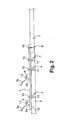
- the power supply return device according to the invention is shown schematically in FIG.
- This device applies to avionic avionics devices 1a, 1b arranged on a conductive composite structure 2 of a part of an aircraft such as a box or a tank.
- the conductive composite structures employed frequently contain carbon particles or are made of laminated material comprising aluminum foils.
- the invention solves the problem of the risks caused by this lack of conductivity of the structure, in particular by creating an electric current return device isolated from this structure.
- the device comprises at least one conductive metal bar 3.
- This bar secured to the conductive composite structure through insulating fixing means 4, will convey the return current of the equipment 1a, 1b to a metal structure 7 adapted to the passage strong currents and constituting a mass or zero reference electric potential, such a metal structure being called the primary electrical structure of the aircraft.
- the bar 3 is connected to this primary electrical structure 7 by an electrical connection element 6 which according to the example shown is also a fixing element 16, 16a, 16b of the metal bar 3 on the primary electrical structure 7, for example a screw of highly electrically conductive material.
- an electrical connection element 6 which according to the example shown is also a fixing element 16, 16a, 16b of the metal bar 3 on the primary electrical structure 7, for example a screw of highly electrically conductive material.
- the bar 3 is then positioned on an insulating support 12 and secured to the conductive composite structure 2 by insulating fixing means constituted according to the example shown in Figure 2 by screws 10 fixed in the conductive composite structure through insulating sleeves 11 or by any type of fixation (insulating members such as fixing clips for example).
- the bar may be straight or have a curved or sinuous profile to approach the embedded devices 1a, 1b to which it must be connected.
- the bar comprises at least one electrical connection member 5a, 5b for at least one onboard device 1a, 1b.
- a connecting member 9 consisting of a connecting plate for a return connection current 8a, 8b per onboard device can be provided.
- connection board comprises a base 9 for receiving a lug 13 connecting the connection 8a, 8b of the onboard devices.
- the bar may, depending on its length and the number of on-board equipment to be connected, comprise a plurality of electrical connection members 5a, 5b spaced in place longitudinally on the conductive metal bar 3 so as to connect several onboard devices 1a. , 1 b distant.
- the invention also makes it possible to provide an electrical return current feedback network running along at least one wall of an internal space of the aircraft, several conductive metal bars 3 forming part of the reported electrical network.
- the device according to the invention may for example be made from bars of predetermined size and having breakable sections to obtain bars of suitable length as a function of the distance of the equipment to the primary electrical structures of the aircraft.
- the network formed may for example go around an internal space of a housing such as an aircraft tank or a box consisting of panels 2 in conductive composite material while remaining electrically isolated from the panels constituting this internal space using the insulating fixing means 4 and the insulating support 12 disposed between the bars 3 of the network and the panels.
- the device according to the invention thus conveniently makes it possible to produce a primary electrical sub-structure reported in the caissons of an aircraft.
Landscapes
- Connections By Means Of Piercing Elements, Nuts, Or Screws (AREA)
- Structure Of Printed Boards (AREA)
- Cable Accessories (AREA)
- Selective Calling Equipment (AREA)
- Control Of Electric Motors In General (AREA)
- Percussion Or Vibration Massage (AREA)
- Connector Housings Or Holding Contact Members (AREA)
- Coupling Device And Connection With Printed Circuit (AREA)
- Vehicle Body Suspensions (AREA)
- Feeding And Watering For Cattle Raising And Animal Husbandry (AREA)
- Catching Or Destruction (AREA)
- Laminated Bodies (AREA)
Claims (9)
- Vorrichtung für die Rückleitung der Stromversorgung für Vorrichtungen (1a, 1b) an Bord von Flugzeugen, die auf einer leitenden Verbundstruktur (2) eines Flugzeugs angeordnet sind, dadurch gekennzeichnet, dass sie wenigstens einen leitenden Metallstab (3) umfasst, der mit der leitenden Verbundstruktur über isolierende Befestigungsmittel (4) verbunden ist, wobei der Stab (3) einerseits wenigstens ein elektrisches Verbindungsorgan (5a, 5b) für wenigstens eine der an Bord vorhandenen Vorrichtungen (1a, 1b) besitzt und andererseits ein elektrisches Verbindungselement (6) mit einer primären elektrischen Struktur (7) des Flugzeugs besitzt.
- Vorrichtung für die Rückleitung der Stromversorgung nach Anspruch 1, dadurch gekennzeichnet, dass das elektrische Verbindungsorgan (5a, 5b) aus einer Verbindungsplatine für einen Stromrückleitungsanschluss (8a, 8b) wenigstens einer an Bord vorhandenen Vorrichtung (1a, 1b) gebildet ist.
- Vorrichtung für die Rückleitung der Stromversorgung nach Anspruch 2, dadurch gekennzeichnet, dass die Verbindungsplatine wenigstens eine Grundfläche (9) für die Aufnahme einer Verbindungshülse (13) für den Anschluss (8a, 8b) aufweist.
- Vorrichtung für die Rückleitung der Stromversorgung nach einem der vorhergehenden Ansprüche, dadurch gekennzeichnet, dass sie mehrere Verbindungsorgane (5a, 5b) aufweist, die von einem Ort zum nächsten in Längsrichtung auf dem leitenden metallischen Stab (3) voneinander beabstandet sind, um mehrere in einem Abstand vorhandene Vorrichtungen (1a, 1b) an Bord zu verbinden.
- Vorrichtung für die Rückleitung der Stromversorgung nach einem der vorhergehenden Ansprüche, dadurch gekennzeichnet, dass das elektrische Verbindungselement (6) ein Element (16, 16a, 16b) für die Befestigung des Metallstabs (3) an der primären elektrischen Struktur (7) ist.
- Vorrichtung für die Rückleitung der Stromversorgung nach Anspruch 5, dadurch gekennzeichnet, dass das Befestigungselement (16, 16a, 16b) aus wenigstens einer Schraube aus einem Material, das Elektrizität gut leitet, gebildet ist.
- Vorrichtung für die Rückleitung der Stromversorgung nach einem der vorhergehenden Ansprüche, dadurch gekennzeichnet, dass die isolierenden Befestigungsmittel Schrauben (10) umfassen, die in der leitenden Verbundstruktur durch isolierende Muffen (11) hindurch befestigt sind.
- Vorrichtung für die Rückleitung der Stromversorgung nach einem der vorhergehenden Ansprüche, dadurch gekennzeichnet, dass der leitende metallische Stab (3) einen Teil eines angefügten elektrischen Netzes bildet, das wenigstens längs einer Wand eines Innenraums des Flugzeugs verläuft.
- Vorrichtung für die Rückleitung der Stromversorgung nach einem der vorhergehenden Ansprüche, dadurch gekennzeichnet, dass zwischen dem leitenden metallischen Stab (3) und der leitenden Verbundstruktur (2) ein isolierender Träger (12) angeordnet ist.
Applications Claiming Priority (2)
| Application Number | Priority Date | Filing Date | Title |
|---|---|---|---|
| FR0401935 | 2004-02-26 | ||
| FR0401935A FR2866991B1 (fr) | 2004-02-26 | 2004-02-26 | Dispositif de retour d'alimentation electrique pour equipements avioniques |
Publications (2)
| Publication Number | Publication Date |
|---|---|
| EP1569303A1 EP1569303A1 (de) | 2005-08-31 |
| EP1569303B1 true EP1569303B1 (de) | 2006-09-20 |
Family
ID=34746444
Family Applications (1)
| Application Number | Title | Priority Date | Filing Date |
|---|---|---|---|
| EP05101160A Expired - Lifetime EP1569303B1 (de) | 2004-02-26 | 2005-02-16 | Versorgungsrückleitungsvorrichtung für Flugzeugausrüstung |
Country Status (7)
| Country | Link |
|---|---|
| US (1) | US7485800B2 (de) |
| EP (1) | EP1569303B1 (de) |
| AT (1) | ATE340421T1 (de) |
| CA (1) | CA2495987C (de) |
| DE (1) | DE602005000133T2 (de) |
| ES (1) | ES2273307T3 (de) |
| FR (1) | FR2866991B1 (de) |
Families Citing this family (8)
| Publication number | Priority date | Publication date | Assignee | Title |
|---|---|---|---|---|
| US20090266935A1 (en) * | 2008-04-28 | 2009-10-29 | Paul Joern | Shell arrangement as well as aircraft or spacecraft |
| US8231080B2 (en) | 2009-02-26 | 2012-07-31 | The Boeing Company | Distributing power in systems having a composite structure |
| DE102009026686A1 (de) * | 2009-06-03 | 2010-12-23 | Airbus France | Anordnung zum Blitzschutz einer elektronischen Einheit |
| FR2948637B1 (fr) * | 2009-07-31 | 2012-01-20 | Airbus Operations Sas | Aeronef comprenant des equipements electriques et des pieces en materiau composite |
| FR2989468B1 (fr) * | 2012-04-17 | 2014-05-23 | Airbus Operations Sas | Procede de controle de la performance des jonctions electriques dans un reseau de retour de courant d'un aeronef. |
| FR3012527B1 (fr) * | 2013-10-30 | 2015-10-30 | Snecma | Metallisation d'un carter electriquement isolant d'un moteur aeronautique |
| FR3012516B1 (fr) * | 2013-10-30 | 2018-01-05 | Safran Aircraft Engines | Metallisation d'un carter d'un moteur aeronautique en materiau electriquement isolant |
| CA3043569A1 (en) * | 2016-11-11 | 2018-05-17 | Bombardier Inc. | Signal return network for composite aircraft |
Family Cites Families (6)
| Publication number | Priority date | Publication date | Assignee | Title |
|---|---|---|---|---|
| US3989984A (en) * | 1975-07-11 | 1976-11-02 | Mcdonnell Douglas Corporation | Aircraft lightning protection means |
| US4502092A (en) * | 1982-09-30 | 1985-02-26 | The Boeing Company | Integral lightning protection system for composite aircraft skins |
| FR2687195B1 (fr) * | 1992-02-12 | 1995-07-07 | Eurocopter France | Organe d'assemblage a tete fraisee, tel qu'un rivet, pour l'assemblage de pieces en materiau composite munies de revetements electriquement conducteurs, et structure obtenue par cet assemblage. |
| GB9807198D0 (en) * | 1998-04-04 | 1998-06-03 | British Aerospace | Adhesively bonded joints in carbon fibre composite structures |
| ES2162718A1 (es) * | 1998-07-29 | 2002-01-01 | Const Aeronauticas Sa | Un sistema de proteccion contra descargas electricas, especialmente rayos, de componentes estructurales de aviones. |
| DE19936640B4 (de) * | 1999-08-04 | 2008-01-10 | Airbus Deutschland Gmbh | Masseverbindung zwischen gelenkig miteinander verbundenen Bauteilen eines Flugzeuges |
-
2004
- 2004-02-26 FR FR0401935A patent/FR2866991B1/fr not_active Expired - Fee Related
-
2005
- 2005-02-04 CA CA2495987A patent/CA2495987C/fr not_active Expired - Fee Related
- 2005-02-16 AT AT05101160T patent/ATE340421T1/de not_active IP Right Cessation
- 2005-02-16 ES ES05101160T patent/ES2273307T3/es not_active Expired - Lifetime
- 2005-02-16 EP EP05101160A patent/EP1569303B1/de not_active Expired - Lifetime
- 2005-02-16 DE DE602005000133T patent/DE602005000133T2/de not_active Expired - Lifetime
- 2005-02-18 US US11/061,180 patent/US7485800B2/en not_active Expired - Fee Related
Also Published As
| Publication number | Publication date |
|---|---|
| EP1569303A1 (de) | 2005-08-31 |
| DE602005000133T2 (de) | 2007-09-13 |
| CA2495987A1 (fr) | 2005-08-26 |
| US7485800B2 (en) | 2009-02-03 |
| CA2495987C (fr) | 2012-12-18 |
| ES2273307T3 (es) | 2007-05-01 |
| ATE340421T1 (de) | 2006-10-15 |
| FR2866991A1 (fr) | 2005-09-02 |
| US20050190547A1 (en) | 2005-09-01 |
| DE602005000133D1 (de) | 2006-11-02 |
| FR2866991B1 (fr) | 2006-05-19 |
Similar Documents
| Publication | Publication Date | Title |
|---|---|---|
| FR2952762A1 (fr) | Ensemble de montage de contacteur avec caracteristiques thermiques ameliorees | |
| EP1569303B1 (de) | Versorgungsrückleitungsvorrichtung für Flugzeugausrüstung | |
| FR2982712A1 (fr) | Plaque de distribution d'energie electrique comprenant une barre de distribution protegee. | |
| EP3997759B1 (de) | Verbindungsvorrichtung zum erden eines elektrischen gerätes und/oder zur erzeugung einer äquipotenzialverbindung zwischen leitenden elementen | |
| EP0988228B1 (de) | Funkensichere struktur, insbesondere für flugzeuge | |
| EP1120659B1 (de) | Elektrischer Energiezähler | |
| EP2456014A3 (de) | Verbindungsklemme zwischen einer elektrischen umlaufenden Maschine eines Kraftfahrzeugs und einem Stromkreiskabel des besagten Fahrzeugs | |
| EP2131381A1 (de) | Sicherungsgehäuse mit geringem Platzbedarf | |
| FR2952905A1 (fr) | Dispositif d'attache de moyens raidisseurs a un element de cadre, et structure comportant un tel dispositif d'attache | |
| EP3592648A1 (de) | Elektrodynamische anordnung zum antreiben eines raumfahrzeugs in der umlaufbahn um einen stern mit einem magnetfeld | |
| EP4564671A1 (de) | Elektronisch schaltende schutzvorrichtung mit kühlkörper | |
| EP3331336B1 (de) | Kompaktes leistungselektroniksystem für elektrische motorantriebsanlage | |
| WO2017032814A1 (fr) | Élément de commutation pour plaque de distribution d'énergie électrique et boîtier de distribution d'énergie électrique doté d'un tel élément de commutation | |
| EP3727943B1 (de) | Elektrische anschlussleiste für eine elektrische anordnung | |
| FR3076091A1 (fr) | Piece de conduction electrique pour ensemble electrique | |
| FR3109032A1 (fr) | Boîtier de connexion électrique muni de relais déportés | |
| WO2018001891A1 (fr) | Connecteur de raccordement | |
| FR2786612A1 (fr) | Dispositif de raccordement electrique entre un systeme a barres et plusieurs cables conducteurs | |
| CA2338923A1 (fr) | Dispositif de distribution de puissace comportant des barres appliquees sur une platine | |
| EP4113767A1 (de) | Vorrichtung zur elektrischen verbindung von kabeln, die eine platte mit elektrisch isolierten kanälen umfasst, die sammelschienen umschliessen | |
| EP3176881B1 (de) | Elektrischer anschluss, der einen kühlkörper umfasst, und elektrisches gerät, das mit einem solchen anschluss ausgestattet ist | |
| EP0637826A1 (de) | Leistungswiderstand mit Vorrichtung zur Aufbringung unter Druck auf einer Wärmesenke | |
| FR2819112A1 (fr) | Barre conductrice et circuit de distribution de puissance la comportant | |
| EP1443602A1 (de) | Elektrischer Verbinder zum Verbinden eines Kabels zwischen zwei Wagen eines Schienenfahrzeuges | |
| EP0829927A1 (de) | Vorrichtung zur Verbindung einer Stromschiene mit einem elektrischen Leiter |
Legal Events
| Date | Code | Title | Description |
|---|---|---|---|
| PUAI | Public reference made under article 153(3) epc to a published international application that has entered the european phase |
Free format text: ORIGINAL CODE: 0009012 |
|
| AK | Designated contracting states |
Kind code of ref document: A1 Designated state(s): AT BE BG CH CY CZ DE DK EE ES FI FR GB GR HU IE IS IT LI LT LU MC NL PL PT RO SE SI SK TR |
|
| AX | Request for extension of the european patent |
Extension state: AL BA HR LV MK YU |
|
| 17P | Request for examination filed |
Effective date: 20060125 |
|
| GRAP | Despatch of communication of intention to grant a patent |
Free format text: ORIGINAL CODE: EPIDOSNIGR1 |
|
| AKX | Designation fees paid |
Designated state(s): AT BE BG CH CY CZ DE DK EE ES FI FR GB GR HU IE IS IT LI LT LU MC NL PL PT RO SE SI SK TR |
|
| GRAS | Grant fee paid |
Free format text: ORIGINAL CODE: EPIDOSNIGR3 |
|
| GRAA | (expected) grant |
Free format text: ORIGINAL CODE: 0009210 |
|
| AK | Designated contracting states |
Kind code of ref document: B1 Designated state(s): AT BE BG CH CY CZ DE DK EE ES FI FR GB GR HU IE IS IT LI LT LU MC NL PL PT RO SE SI SK TR |
|
| PG25 | Lapsed in a contracting state [announced via postgrant information from national office to epo] |
Ref country code: IE Free format text: LAPSE BECAUSE OF FAILURE TO SUBMIT A TRANSLATION OF THE DESCRIPTION OR TO PAY THE FEE WITHIN THE PRESCRIBED TIME-LIMIT Effective date: 20060920 Ref country code: AT Free format text: LAPSE BECAUSE OF FAILURE TO SUBMIT A TRANSLATION OF THE DESCRIPTION OR TO PAY THE FEE WITHIN THE PRESCRIBED TIME-LIMIT Effective date: 20060920 Ref country code: IT Free format text: LAPSE BECAUSE OF FAILURE TO SUBMIT A TRANSLATION OF THE DESCRIPTION OR TO PAY THE FEE WITHIN THE PRESCRIBED TIME-LIMIT;WARNING: LAPSES OF ITALIAN PATENTS WITH EFFECTIVE DATE BEFORE 2007 MAY HAVE OCCURRED AT ANY TIME BEFORE 2007. THE CORRECT EFFECTIVE DATE MAY BE DIFFERENT FROM THE ONE RECORDED. Effective date: 20060920 Ref country code: NL Free format text: LAPSE BECAUSE OF FAILURE TO SUBMIT A TRANSLATION OF THE DESCRIPTION OR TO PAY THE FEE WITHIN THE PRESCRIBED TIME-LIMIT Effective date: 20060920 Ref country code: SI Free format text: LAPSE BECAUSE OF FAILURE TO SUBMIT A TRANSLATION OF THE DESCRIPTION OR TO PAY THE FEE WITHIN THE PRESCRIBED TIME-LIMIT Effective date: 20060920 Ref country code: FI Free format text: LAPSE BECAUSE OF FAILURE TO SUBMIT A TRANSLATION OF THE DESCRIPTION OR TO PAY THE FEE WITHIN THE PRESCRIBED TIME-LIMIT Effective date: 20060920 Ref country code: LT Free format text: LAPSE BECAUSE OF FAILURE TO SUBMIT A TRANSLATION OF THE DESCRIPTION OR TO PAY THE FEE WITHIN THE PRESCRIBED TIME-LIMIT Effective date: 20060920 Ref country code: CZ Free format text: LAPSE BECAUSE OF FAILURE TO SUBMIT A TRANSLATION OF THE DESCRIPTION OR TO PAY THE FEE WITHIN THE PRESCRIBED TIME-LIMIT Effective date: 20060920 Ref country code: SK Free format text: LAPSE BECAUSE OF FAILURE TO SUBMIT A TRANSLATION OF THE DESCRIPTION OR TO PAY THE FEE WITHIN THE PRESCRIBED TIME-LIMIT Effective date: 20060920 Ref country code: RO Free format text: LAPSE BECAUSE OF FAILURE TO SUBMIT A TRANSLATION OF THE DESCRIPTION OR TO PAY THE FEE WITHIN THE PRESCRIBED TIME-LIMIT Effective date: 20060920 Ref country code: PL Free format text: LAPSE BECAUSE OF FAILURE TO SUBMIT A TRANSLATION OF THE DESCRIPTION OR TO PAY THE FEE WITHIN THE PRESCRIBED TIME-LIMIT Effective date: 20060920 |
|
| REG | Reference to a national code |
Ref country code: GB Ref legal event code: FG4D Free format text: NOT ENGLISH |
|
| REG | Reference to a national code |
Ref country code: CH Ref legal event code: EP |
|
| REG | Reference to a national code |
Ref country code: IE Ref legal event code: FG4D Free format text: LANGUAGE OF EP DOCUMENT: FRENCH |
|
| REF | Corresponds to: |
Ref document number: 602005000133 Country of ref document: DE Date of ref document: 20061102 Kind code of ref document: P |
|
| PG25 | Lapsed in a contracting state [announced via postgrant information from national office to epo] |
Ref country code: BG Free format text: LAPSE BECAUSE OF FAILURE TO SUBMIT A TRANSLATION OF THE DESCRIPTION OR TO PAY THE FEE WITHIN THE PRESCRIBED TIME-LIMIT Effective date: 20061220 Ref country code: DK Free format text: LAPSE BECAUSE OF FAILURE TO SUBMIT A TRANSLATION OF THE DESCRIPTION OR TO PAY THE FEE WITHIN THE PRESCRIBED TIME-LIMIT Effective date: 20061220 |
|
| REG | Reference to a national code |
Ref country code: SE Ref legal event code: TRGR |
|
| GBT | Gb: translation of ep patent filed (gb section 77(6)(a)/1977) |
Effective date: 20061227 |
|
| PG25 | Lapsed in a contracting state [announced via postgrant information from national office to epo] |
Ref country code: IS Free format text: LAPSE BECAUSE OF FAILURE TO SUBMIT A TRANSLATION OF THE DESCRIPTION OR TO PAY THE FEE WITHIN THE PRESCRIBED TIME-LIMIT Effective date: 20070120 |
|
| PG25 | Lapsed in a contracting state [announced via postgrant information from national office to epo] |
Ref country code: MC Free format text: LAPSE BECAUSE OF NON-PAYMENT OF DUE FEES Effective date: 20070228 |
|
| NLV1 | Nl: lapsed or annulled due to failure to fulfill the requirements of art. 29p and 29m of the patents act | ||
| PG25 | Lapsed in a contracting state [announced via postgrant information from national office to epo] |
Ref country code: PT Free format text: LAPSE BECAUSE OF FAILURE TO SUBMIT A TRANSLATION OF THE DESCRIPTION OR TO PAY THE FEE WITHIN THE PRESCRIBED TIME-LIMIT Effective date: 20070312 |
|
| REG | Reference to a national code |
Ref country code: IE Ref legal event code: FD4D |
|
| REG | Reference to a national code |
Ref country code: ES Ref legal event code: FG2A Ref document number: 2273307 Country of ref document: ES Kind code of ref document: T3 |
|
| PLBE | No opposition filed within time limit |
Free format text: ORIGINAL CODE: 0009261 |
|
| STAA | Information on the status of an ep patent application or granted ep patent |
Free format text: STATUS: NO OPPOSITION FILED WITHIN TIME LIMIT |
|
| 26N | No opposition filed |
Effective date: 20070621 |
|
| BERE | Be: lapsed |
Owner name: AIRBUS FRANCE Effective date: 20070228 |
|
| PG25 | Lapsed in a contracting state [announced via postgrant information from national office to epo] |
Ref country code: BE Free format text: LAPSE BECAUSE OF NON-PAYMENT OF DUE FEES Effective date: 20070228 |
|
| PG25 | Lapsed in a contracting state [announced via postgrant information from national office to epo] |
Ref country code: GR Free format text: LAPSE BECAUSE OF FAILURE TO SUBMIT A TRANSLATION OF THE DESCRIPTION OR TO PAY THE FEE WITHIN THE PRESCRIBED TIME-LIMIT Effective date: 20061221 |
|
| PG25 | Lapsed in a contracting state [announced via postgrant information from national office to epo] |
Ref country code: EE Free format text: LAPSE BECAUSE OF FAILURE TO SUBMIT A TRANSLATION OF THE DESCRIPTION OR TO PAY THE FEE WITHIN THE PRESCRIBED TIME-LIMIT Effective date: 20060920 |
|
| PGRI | Patent reinstated in contracting state [announced from national office to epo] |
Ref country code: IT Effective date: 20090401 |
|
| PG25 | Lapsed in a contracting state [announced via postgrant information from national office to epo] |
Ref country code: LU Free format text: LAPSE BECAUSE OF NON-PAYMENT OF DUE FEES Effective date: 20070216 Ref country code: CY Free format text: LAPSE BECAUSE OF FAILURE TO SUBMIT A TRANSLATION OF THE DESCRIPTION OR TO PAY THE FEE WITHIN THE PRESCRIBED TIME-LIMIT Effective date: 20060920 |
|
| PG25 | Lapsed in a contracting state [announced via postgrant information from national office to epo] |
Ref country code: TR Free format text: LAPSE BECAUSE OF FAILURE TO SUBMIT A TRANSLATION OF THE DESCRIPTION OR TO PAY THE FEE WITHIN THE PRESCRIBED TIME-LIMIT Effective date: 20060920 Ref country code: HU Free format text: LAPSE BECAUSE OF FAILURE TO SUBMIT A TRANSLATION OF THE DESCRIPTION OR TO PAY THE FEE WITHIN THE PRESCRIBED TIME-LIMIT Effective date: 20070321 |
|
| REG | Reference to a national code |
Ref country code: CH Ref legal event code: PL |
|
| PG25 | Lapsed in a contracting state [announced via postgrant information from national office to epo] |
Ref country code: CH Free format text: LAPSE BECAUSE OF NON-PAYMENT OF DUE FEES Effective date: 20090228 Ref country code: LI Free format text: LAPSE BECAUSE OF NON-PAYMENT OF DUE FEES Effective date: 20090228 |
|
| REG | Reference to a national code |
Ref country code: GB Ref legal event code: 732E Free format text: REGISTERED BETWEEN 20110721 AND 20110727 |
|
| REG | Reference to a national code |
Ref country code: FR Ref legal event code: TP Owner name: AIRBUS HOLDING, FR Effective date: 20110913 Ref country code: FR Ref legal event code: CJ Effective date: 20110916 Ref country code: FR Ref legal event code: CA Effective date: 20110916 Ref country code: FR Ref legal event code: CD Owner name: AIRBUS HOLDING, FR Effective date: 20110916 |
|
| REG | Reference to a national code |
Ref country code: ES Ref legal event code: PC2A Owner name: AIRBUS OPERATIONS SAS Effective date: 20120308 |
|
| REG | Reference to a national code |
Ref country code: DE Ref legal event code: R082 Ref document number: 602005000133 Country of ref document: DE Representative=s name: SPARING - ROEHL - HENSELER, DE |
|
| REG | Reference to a national code |
Ref country code: DE Ref legal event code: R082 Ref document number: 602005000133 Country of ref document: DE Representative=s name: SPARING - ROEHL - HENSELER, DE Effective date: 20120326 Ref country code: DE Ref legal event code: R081 Ref document number: 602005000133 Country of ref document: DE Owner name: AIRBUS OPERATIONS SAS, FR Free format text: FORMER OWNER: AIRBUS FRANCE, TOULOUSE, FR Effective date: 20120326 |
|
| PGFP | Annual fee paid to national office [announced via postgrant information from national office to epo] |
Ref country code: SE Payment date: 20130219 Year of fee payment: 9 |
|
| REG | Reference to a national code |
Ref country code: SE Ref legal event code: EUG |
|
| PG25 | Lapsed in a contracting state [announced via postgrant information from national office to epo] |
Ref country code: SE Free format text: LAPSE BECAUSE OF NON-PAYMENT OF DUE FEES Effective date: 20140217 |
|
| REG | Reference to a national code |
Ref country code: FR Ref legal event code: PLFP Year of fee payment: 12 |
|
| REG | Reference to a national code |
Ref country code: FR Ref legal event code: PLFP Year of fee payment: 13 |
|
| REG | Reference to a national code |
Ref country code: FR Ref legal event code: PLFP Year of fee payment: 14 |
|
| PGFP | Annual fee paid to national office [announced via postgrant information from national office to epo] |
Ref country code: FR Payment date: 20190124 Year of fee payment: 19 Ref country code: ES Payment date: 20190320 Year of fee payment: 15 |
|
| PGFP | Annual fee paid to national office [announced via postgrant information from national office to epo] |
Ref country code: GB Payment date: 20200219 Year of fee payment: 16 Ref country code: DE Payment date: 20200219 Year of fee payment: 16 |
|
| REG | Reference to a national code |
Ref country code: ES Ref legal event code: FD2A Effective date: 20210706 |
|
| PG25 | Lapsed in a contracting state [announced via postgrant information from national office to epo] |
Ref country code: ES Free format text: LAPSE BECAUSE OF NON-PAYMENT OF DUE FEES Effective date: 20200217 |
|
| REG | Reference to a national code |
Ref country code: DE Ref legal event code: R119 Ref document number: 602005000133 Country of ref document: DE |
|
| GBPC | Gb: european patent ceased through non-payment of renewal fee |
Effective date: 20210216 |
|
| PG25 | Lapsed in a contracting state [announced via postgrant information from national office to epo] |
Ref country code: IT Free format text: LAPSE BECAUSE OF FAILURE TO SUBMIT A TRANSLATION OF THE DESCRIPTION OR TO PAY THE FEE WITHIN THE PRESCRIBED TIME-LIMIT Effective date: 20200216 |
|
| PG25 | Lapsed in a contracting state [announced via postgrant information from national office to epo] |
Ref country code: DE Free format text: LAPSE BECAUSE OF NON-PAYMENT OF DUE FEES Effective date: 20210901 Ref country code: GB Free format text: LAPSE BECAUSE OF NON-PAYMENT OF DUE FEES Effective date: 20210216 Ref country code: FR Free format text: LAPSE BECAUSE OF NON-PAYMENT OF DUE FEES Effective date: 20210228 |