EP1569102B1 - Flash memory programming - Google Patents
Flash memory programming Download PDFInfo
- Publication number
- EP1569102B1 EP1569102B1 EP04388033A EP04388033A EP1569102B1 EP 1569102 B1 EP1569102 B1 EP 1569102B1 EP 04388033 A EP04388033 A EP 04388033A EP 04388033 A EP04388033 A EP 04388033A EP 1569102 B1 EP1569102 B1 EP 1569102B1
- Authority
- EP
- European Patent Office
- Prior art keywords
- memory
- updated
- program code
- module
- object module
- Prior art date
- Legal status (The legal status is an assumption and is not a legal conclusion. Google has not performed a legal analysis and makes no representation as to the accuracy of the status listed.)
- Expired - Lifetime
Links
- 230000015654 memory Effects 0.000 title claims abstract description 158
- 238000000034 method Methods 0.000 claims abstract description 54
- 230000001131 transforming effect Effects 0.000 claims abstract description 10
- 238000004891 communication Methods 0.000 claims description 22
- 238000012545 processing Methods 0.000 claims description 21
- 238000004590 computer program Methods 0.000 claims description 5
- 230000008569 process Effects 0.000 description 23
- 238000010586 diagram Methods 0.000 description 8
- 230000008901 benefit Effects 0.000 description 7
- 230000006870 function Effects 0.000 description 6
- 230000010267 cellular communication Effects 0.000 description 3
- 230000008859 change Effects 0.000 description 3
- 238000012986 modification Methods 0.000 description 3
- 230000004048 modification Effects 0.000 description 3
- 230000003466 anti-cipated effect Effects 0.000 description 2
- 238000003491 array Methods 0.000 description 2
- 230000007246 mechanism Effects 0.000 description 2
- 230000001413 cellular effect Effects 0.000 description 1
- 238000012937 correction Methods 0.000 description 1
- 230000001419 dependent effect Effects 0.000 description 1
- 230000000694 effects Effects 0.000 description 1
- 238000003780 insertion Methods 0.000 description 1
- 230000037431 insertion Effects 0.000 description 1
- 230000009191 jumping Effects 0.000 description 1
- 238000012795 verification Methods 0.000 description 1
Images

Classifications
-
- G—PHYSICS
- G06—COMPUTING; CALCULATING OR COUNTING
- G06F—ELECTRIC DIGITAL DATA PROCESSING
- G06F8/00—Arrangements for software engineering
- G06F8/60—Software deployment
- G06F8/65—Updates
- G06F8/654—Updates using techniques specially adapted for alterable solid state memories, e.g. for EEPROM or flash memories
-
- G—PHYSICS
- G06—COMPUTING; CALCULATING OR COUNTING
- G06F—ELECTRIC DIGITAL DATA PROCESSING
- G06F3/00—Input arrangements for transferring data to be processed into a form capable of being handled by the computer; Output arrangements for transferring data from processing unit to output unit, e.g. interface arrangements
- G06F3/12—Digital output to print unit, e.g. line printer, chain printer
- G06F3/1293—Printer information exchange with computer
- G06F3/1294—Status or feedback related to information exchange
-
- G—PHYSICS
- G06—COMPUTING; CALCULATING OR COUNTING
- G06F—ELECTRIC DIGITAL DATA PROCESSING
- G06F8/00—Arrangements for software engineering
- G06F8/40—Transformation of program code
- G06F8/41—Compilation
- G06F8/44—Encoding
- G06F8/443—Optimisation
-
- G—PHYSICS
- G06—COMPUTING; CALCULATING OR COUNTING
- G06F—ELECTRIC DIGITAL DATA PROCESSING
- G06F9/00—Arrangements for program control, e.g. control units
- G06F9/06—Arrangements for program control, e.g. control units using stored programs, i.e. using an internal store of processing equipment to receive or retain programs
- G06F9/44—Arrangements for executing specific programs
- G06F9/445—Program loading or initiating
-
- G—PHYSICS
- G11—INFORMATION STORAGE
- G11C—STATIC STORES
- G11C16/00—Erasable programmable read-only memories
- G11C16/02—Erasable programmable read-only memories electrically programmable
- G11C16/06—Auxiliary circuits, e.g. for writing into memory
- G11C16/10—Programming or data input circuits
- G11C16/102—External programming circuits, e.g. EPROM programmers; In-circuit programming or reprogramming; EPROM emulators
Definitions
- Flash memory is a popular type of memory in electronic devices, because it allows multiple rewrites. However, the write operations are limited to entire memory sectors, so-called pages, at a time.
- a typical page size of current flash memories is 64 kbyte.
- a code generation system comprises a compiler which compiles a source code and generates a number of object code modules, and a linker which generates the executable code.
- the linker resolves dependencies between the set of object code modules that constitute a software development project.
- the tasks of the linker generally include laying out the object modules in memory, i.e. assigning relative addresses to the different object modules in a corresponding address space. Hence, at the linker stage, the necessary information about the layout of the code in the memory space is available.
- the object module is typically represented as an object file in a low-level file format that is hardware and/or platform specific.
- the object file is generated by a compiler and serves as an input to the linker.
- An object module is typically relocatable and contains unresolved references.
- the optimisation process is performed at the linker stage.
- the input code comprises a number of object modules and the transforming comprises linking the number of object modules.
- the optimisation process comprises determining the layout of said object modules in memory.
- determining the layout of said object modules in memory comprises
- determining the layout of said object modules in memory comprises
- the method further comprises generating a delta file representative of differences between the current program code version and the updated program code version.
- the resulting delta file includes the differences between the current and updated versions, i.e. the information required for the device to generate the updated version from the current version stored in the device and the delta file. It is an advantage of this embodiment, that the size of the file that needs to be uploaded to the device is reduced, thereby further reducing the time required to perform a software update.
- processing means comprises any circuit and/or device suitably adapted to perform the above functions.
- processing means comprises general- or special-purpose programmable microprocessors, Digital Signal Processors (DSP), Application Specific Integrated Circuits (ASIC), Programmable Logic Arrays (PLA), Field Programmable Gate Arrays (FPGA), special purpose electronic circuits, etc., or a combination thereof.
- the present invention can be implemented in different ways including the method described above and in the following, a data processing system, and further product means, each yielding one or more of the benefits and advantages described in connection with the first-mentioned method, and each having one or more preferred embodiments corresponding to the preferred embodiments described in connection with the first-mentioned method.
- the invention relates to a data processing system for updating program code stored in a memory, the memory comprising a plurality of memory sectors, the data processing system being suitably programmed to perform the steps of the method described above and in the following.
- the term electronic device comprises any device comprising a memory such as a flash memory for storing program code.
- Examples of such devices include portable radio communications equipment and other handheld or portable devices.
- portable radio communications equipment includes all equipment such as mobile telephones, pagers, communicators, i.e. electronic organisers, smart phones, personal digital assistants (PDAs), handheld computers, or the like.
- the software updating system further comprises a processing unit 105, e.g. the CPU of a server computer, suitably programmed to control and perform the update process including the generation of the updated program code as described herein.
- the processing unit further comprises a version database 106 having stored therein memory images of at least a base version and an updated version of the software to be updated.
- the version database may further comprise additional information, e.g. a plurality of base versions and/or updated versions, e.g. for different models of mobile terminals, for different groups of customers, and/or the like.
- the linker module 302 further receives information about a previous build file 303, e.g. in the form of an image of the corresponding address space in a flash memory where the current build is stored.
- the linker 302 may also generate a text-file representation of the memory layout of the current build, a so-called map file.
- the map file may comprise a list of functions, the addresses assigned to them, their input parameters, etc.
- the information 303 about the previous build may comprise the corresponding map file of the previous build.
- the linker module receives both the map file and the memory image of the previous build.
- the linker module 302 further receives one or more optimisation parameters 304 for controlling the optimisation steps.
- the optimisation parameters may determine which optimisation steps the linker should perform.
- the optimisation parameters may determine a number of limitations or boundary conditions for one or more of the optimisation steps.
- the linker may be configured to reduce, preferably to minimize, the difference between the new build and the previous build within a number of limitations or boundary conditions determined by the optimisation parameters.
- Fig. 4 schematically illustrates the memory layout of a flash memory before and after a software update where the layout is optimised via an introduction of padding space.
- the layout may be optimised by merely adding a suitable padding space ensuring an unchanged base address of module B, i.e. without moving B.
- the above optimisation of the memory layout by adding a padding space reduces the number of necessary re-writes at the cost of an increased size of the memory image corresponding to the size of the additional padding space.
- this trade-off can be controlled by a optimisation parameter that determines the maximum size of padding space allowed to be inserted by the linker.
- Fig. 5a illustrates the structure of a part of the address space of a flash memory.
- the address space 501 is divided into a number of pages denoted P1, P2, P3, P4, P5, P6, P7, and P8.
- the pages have a predetermined size S.
- the determination of the layout of the object modules in memory comprises
Landscapes
- Engineering & Computer Science (AREA)
- Theoretical Computer Science (AREA)
- Software Systems (AREA)
- General Engineering & Computer Science (AREA)
- Physics & Mathematics (AREA)
- General Physics & Mathematics (AREA)
- Computer Security & Cryptography (AREA)
- Human Computer Interaction (AREA)
- Stored Programmes (AREA)
- Medicines Containing Plant Substances (AREA)
- Techniques For Improving Reliability Of Storages (AREA)
Abstract
Description
- This invention relates to the updating of program code stored in a memory, which memory comprises a plurality of memory sectors.
- Many modern electronic devices, e.g. embedded devices, are controlled by software stored on flash memory. Flash memory is a popular type of memory in electronic devices, because it allows multiple rewrites. However, the write operations are limited to entire memory sectors, so-called pages, at a time. A typical page size of current flash memories is 64 kbyte.
- When the software stored in a flash memory of an electronic device is updated, e.g. in order to add new features to the software and/or to correct errors in the current version of the software, some or all of the memory sectors of the flash memory are re-written or "re-flashed". In general, it is desirable to minimize the number of flash pages that are re-written during a software update, in order to minimize the time required for installing the software update.
- In particular, an application where update times are of great concern is the over-the-air (OTA) update of mobile terminals. In such applications, it is known to distribute only modifications to the current image to the mobile terminal rather than the entire updated image. The modifications are generally referred to as delta-files. In such systems, an update agent running on the mobile terminal applies the received modifications to the current image which is thereby transformed to the updated version. It is a particular problem of such update systems that the terminal is not functional during the update process. Hence, it is desirable to reduce the time required for reflashing the memory and, thus, the downtime of the system.
- However, due to the constraints of the flash memory mentioned above, even small updates of the source code of the software may cause a large portion of the flash pages to be updated, since changing even a single byte requires an entire page to be completely rewritten.
- International application
WO 03/009136 - Published
US application 2003/0142556 discloses a method of flash memory programming, wherein volatile information or volatile software components are stored at least near the end of the respective flash memory address space of the flash memory device to keep the need of changing or adjusting flash sectors as slight as possible. - However, the above prior art method requires information about the anticipated likelihood of changing the respective information components. Hence, the above prior art does not address the problem of reducing the number of required re-writes when updating program code in a memory with a plurality of memory sectors, without requiring information about the anticipated likelihood of future changes in the respective software components.
- The above and other problems are solved by a method for updating program code stored in a memory, which memory comprises a plurality of memory sectors, the method comprising
- transforming an updated input code into an updated program code version to be stored in a memory, which memory has stored thereon a current program code version occupying a first set of the memory sectors of the memory, wherein the updated program code version occupies a second set of memory sectors when stored in the memory;
- receiving a representation of the current program code version; and
- performing at least one optimisation step adapted to decrease the number of memory sectors of the second set of memory sectors occupied by the updated code version that are different from the corresponding memory sectors of the first set of memory sectors occupied by the current program code version.
- In particular, by receiving a representation of the current program code version; and performing at least one optimisation process adapted to decrease the number of memory sectors of the second set of memory sectors occupied by the updated code version that are different from the corresponding memory sectors of the first set of memory sectors occupied by the current program code version, the number of required re-writes is reduced.
- As the current program code version stored in the memory is generally known to the process that generates a software update, the above optimisation is based on information that is readily available to the updating process. In particular, the process is based on information about the currently installed version and the current update, whereas no information about the likelihood of any future updates is required.
- In a preferred embodiment, the representation of the current program code version comprises a current image of the first set of memory sectors and/or a map file description of the current image of the first set of memory sectors. Consequently, the representation comprises information about the layout of the program code components in the memory, thereby allowing the optimisation process to adapt the layout of the updated components as to reduce the differences between both versions.
- Typically, a code generation system comprises a compiler which compiles a source code and generates a number of object code modules, and a linker which generates the executable code. The linker resolves dependencies between the set of object code modules that constitute a software development project. The tasks of the linker generally include laying out the object modules in memory, i.e. assigning relative addresses to the different object modules in a corresponding address space. Hence, at the linker stage, the necessary information about the layout of the code in the memory space is available. The object module is typically represented as an object file in a low-level file format that is hardware and/or platform specific. The object file is generated by a compiler and serves as an input to the linker. An object module is typically relocatable and contains unresolved references.
- Here the term layout of the code in memory comprises the respective start or base addresses of the different object modules, i.e. their respective relative addresses within the address space occupied by the program code.
- Consequently, in a preferred embodiment of the invention, the optimisation process is performed at the linker stage. Hence, the input code comprises a number of object modules and the transforming comprises linking the number of object modules. Preferably, the optimisation process comprises determining the layout of said object modules in memory.
- In another preferred embodiment, the input code comprises at least one source code module; the transforming comprises
- compiling the at least one source code module resulting in a number of object modules; and
- linking the number of object modules;
- generating feedback data during the linking step; and
- re-compiling at least a subset of the source code modules based on the feedback data and resulting in a number of modified object modules; and
- performing the linking step based on the number of modified object modules.
- Consequently, according to this embodiment, the linker generates feedback to the compiler stage causing the compiler to re-compile at least a part of the source code. This has the advantage that the linker controls the resulting set of object modules, thereby increasing the degrees of freedom of re-arranging object code modules by the linker.
- In yet another preferred embodiment, the transforming further comprises controlling the optimisation process by at least one optimisation parameter. Hence, a mechanism for controlling the optimisation process is provided. In some embodiments the optimisation parameters determine one or more limitations for the optimisation process. For example, one or more of the optimisation parameters may determine a maximum allowed increase in size caused by the optimisation process such as a maximum size of padding space allowed to be added by the optimisation process. Alternatively or additionally, at least one optimisation parameter may include a parameter determining a maximum allowed number of relays introduced by the optimisation process.
- It is an advantage of the invention that the trade-off between the benefits - in terms of the required number of re-writes - and the costs - in terms of memory size, execution time, etc. - of the optimisation process may easily be controlled.
- Accordingly, in a preferred embodiment, determining the layout of said object modules in memory comprises
- detecting an updated first object module having a different size than a corresponding first current object module, and an updated second object module equal to a corresponding second current object module, which updated second object module has a base address larger than the base address of the updated first object module; and
- padding the detected updated first object module with a predetermined memory content of a predetermined padding size resulting in a padded updated first object module; wherein the padding size is selected to cause the base address of the updated second object module to be equal to the base address of the corresponding second current object module.
- In another preferred embodiment, determining the layout of said object modules in memory comprises
- detecting an updated first object module that is larger than a corresponding first current object module;
- moving a predetermined part of the updated first object module to a different memory sector resulting in a reduced updated first object module and a moved part of the updated first object module;
- inserting a relay to the moved part of the updated first object module in the reduced first updated memory sector.
- In yet another preferred embodiment, the method further comprises generating a delta file representative of differences between the current program code version and the updated program code version. Hence, the resulting delta file includes the differences between the current and updated versions, i.e. the information required for the device to generate the updated version from the current version stored in the device and the delta file. It is an advantage of this embodiment, that the size of the file that needs to be uploaded to the device is reduced, thereby further reducing the time required to perform a software update.
- Further preferred embodiments are disclosed in the dependant claims.
- It is noted that the features of the method described above and in the following may be implemented in software and carried out on a data processing system or other processing means caused by the execution of program code means such as computer-executable instructions. Here, and in the following, the term processing means comprises any circuit and/or device suitably adapted to perform the above functions. In particular, the term processing means comprises general- or special-purpose programmable microprocessors, Digital Signal Processors (DSP), Application Specific Integrated Circuits (ASIC), Programmable Logic Arrays (PLA), Field Programmable Gate Arrays (FPGA), special purpose electronic circuits, etc., or a combination thereof.
- For example, the program code means may be loaded in a memory, such as a RAM, from a storage medium or from another computer via a computer network. Alternatively, the described features may be implemented by hardwired circuitry instead of software or in combination with software.
- The present invention can be implemented in different ways including the method described above and in the following, a data processing system, and further product means, each yielding one or more of the benefits and advantages described in connection with the first-mentioned method, and each having one or more preferred embodiments corresponding to the preferred embodiments described in connection with the first-mentioned method.
- In particular, the invention relates to a data processing system for updating program code stored in a memory, the memory comprising a plurality of memory sectors, the data processing system being suitably programmed to perform the steps of the method described above and in the following.
- The invention further relates to a computer program product comprising program code means adapted to cause a data processing system to perform the method described above and in the following, when said program code means are executed on the data processing system. The computer program product may be embodied as a computer-readable medium having stored thereon said program code means.
- For the purpose of the present description, the term electronic device comprises any device comprising a memory such as a flash memory for storing program code. Examples of such devices include portable radio communications equipment and other handheld or portable devices. The term portable radio communications equipment includes all equipment such as mobile telephones, pagers, communicators, i.e. electronic organisers, smart phones, personal digital assistants (PDAs), handheld computers, or the like.
- The above and other aspects of the invention will be apparent and elucidated from the embodiments described in the following with reference to the drawing in which:
-
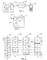
fig. 1 schematically shows a block diagram of an embodiment of a system for updating software in a mobile terminal; -
fig. 2 schematically shows a block diagram of a mobile terminal according to an embodiment of the invention; -
fig. 3 shows a block diagram of an embodiment of a software update process; -
fig. 4 schematically illustrates the memory layout of a flash memory before and after a software update where the layout is optimised via an introduction of padding space; -
fig. 5 schematically illustrates the memory layout of a flash memory before and after a software update where the layout is optimised via an introduction of a relay; -
fig. 6 shows a block diagram of another embodiment of a software update process; -
Fig. 1 schematically shows a block diagram of an embodiment of a system for updating software in an electronic device such as a mobile terminal. The system comprises amobile terminal 101, e.g. a mobile telephone or the like, asoftware updating system 102, and acommunications interface 103. - The
software updating system 102 may comprise a server computer having access to the communications network. In some embodiments, the functionality of the server computer may be distributed among a plurality of computers, e.g. computers connected via a computer network, e.g. a local area network, a wide area network, an Internet, or the like. Thesoftware updating system 102 comprises aninterface circuit 104 allowing the software updating system to communicate data via thecommunications interface 103. For example, the interface circuit may comprise a serial port, a parallel port, a short range wireless communications interface, e.g. an infrared port, a Bluetooth transceiver, or the like. Further examples of interface circuits include a network card, a DSL modem, a gateway computer, or the like. - The software updating system further comprises a
processing unit 105, e.g. the CPU of a server computer, suitably programmed to control and perform the update process including the generation of the updated program code as described herein. The processing unit further comprises aversion database 106 having stored therein memory images of at least a base version and an updated version of the software to be updated. In some embodiments, the version database may further comprise additional information, e.g. a plurality of base versions and/or updated versions, e.g. for different models of mobile terminals, for different groups of customers, and/or the like. - The
communications interface 103 may be any suitable wired or wireless communications interface for communicating data between thesoftware updating system 102 and themobile terminal 101. For example, in the case of a mobile telephone adapted to communicate via a cellular communications network, e.g. a GSM network, a UMTS network, a GPRS network, or the like, the communication between the software updating system and the mobile terminal in connection with a software update may be performed via that cellular communications network, thereby avoiding the need for additional communications interfaces in the mobile terminal. It is further understood that the communication between the mobile terminal and the software updating system may involve more than one communications networks. For example, the mobile phone may communicate via a base station and a cellular telecom network with a gateway system that, in turn, provides communication with the software updating system via the Internet. - Hence, in order to update software on the
mobile terminal 101, e.g. the firmware or operating system of the mobile terminal, the mobile terminal connects to thesoftware updating system 102. Alternatively, the software updating system may connect to the mobile terminal once an updated software version is available. Once connected to the software updating system, the mobile terminal sends information to the software updating system about its current software version. The communication is performed via a suitable updating protocol, e.g. a protocol built on top of a TCI/IP protocol. Based on the information received from the mobile terminal, the software updating system generates a dedicated updating message comprising updating instructions to the mobile terminal. In some embodiments, the updating instructions include the images of the memory sectors to be rewritten. In a differential updating system using delta files, the updating instructions are generated such that they enable the mobile terminal to generate the updated software version from the existing version already stored in the mobile terminal and from additional information included in the updating instructions. - In one embodiment, the update process is initiated by an update agent running on the mobile terminal. The update agent controls the reception and verification of the delta file. Subsequently, the update agent causes the mobile terminal to be disconnected from the network and rebooted in a patch mode. In patch mode, the changes in the delta file are applied incrementally until the new memory image is complete.
- The generation of the delta file generation may schematically be illustrated by the following operations

- Correspondingly, the actual generation of the new version may then be performed by the mobile terminal according to the following operation

- It is understood that the above operations of generating the delta file (denoted as "-" in the above notation) and generating the new version on the mobile terminal (denoted as "+" operation in the above notation) may comprise more or less complex operations.
- The delta file may be applied in-place, i.e. the changes are made by the mobile terminal on the existing image, thereby requiring little additional storage. Furthermore, since only the delta file needs to be loaded and since the delta file typically is considerably smaller than the new version, the loading time is reduced by the above method.
- Embodiments of the code generation process will be described in greater detail below.
-
Fig. 2 schematically shows a block diagram of an electronic device such as a mobile terminal. Themobile terminal 101 comprises acommunications block 210, aprocessing unit 211, ands memory unit 212. - The communications block 210 comprises circuitry and/or devices allowing radio-based communication of data via a cellular communications network. Hence, for the purpose of the present description, the communications block 210 comprises receiver circuitry and transmitter circuitry for receiving and transmitting data signals. The communications block may further comprise circuitry for suitably processing the signals, e.g. modulating, coding, amplifying, etc., the signals by suitable techniques well known in the art of radio communications.
- The mobile terminal further comprises a
processing unit 211, e.g. a suitably programmed microprocessor. The processing unit is adapted to determine the version of the software stored in the mobile terminal, to calculate checksums of the stored software, and to generate an updated version of the software upon receipt of corresponding update instructions. - The
memory unit 212 has stored thereon the software and/or other data in a predetermined version. For example, thememory 212 may comprise the firmware of the mobile terminal that implements the basic functions of the mobile terminal when loaded into and executed by theprocessing unit 210. The firmware may further comprise an operating system allowing application software to be executed. Accordingly, thememory 212 may further have stored thereon application software providing additional functionality. Thememory 212 is addressed using a suitable address space, thereby allowing the processing unit to access selected parts of the memory. In some embodiments thememory 212 may be logically or physically divided in a piuraiity of memory sectors. For example, thememory 212 may comprise flash memory allowing data to be written in sectors of a predetermined size. - In the following, it will be assumed that the
memory 212 is divided in a number of sectors of a predetermined size denoted P1, P2, P3, ..., PN. However, it is understood that any other addressing of the memory may be used, instead. It is further understood that the updating process described herein may be applied to theentire memory 212, e.g. if the entire image of the flash memory of a mobile phone is to be updated, or to only predetermined parts of the memory, e.g. if one or more software applications are to be updated. -
Fig. 3 shows a block diagram of an embodiment of a software update process. Thelinker module 302 receives a number of object files 301. Each of the object files 301 is compiled by a compiler (not shown), wherein some or all of the object files may be compiled separately from each other. Thelinker module 302 combines the object modules into anabsolute file 305 ready for execution. One of the tasks performed by thelinker module 302 is the resolution of cross-references among separately compiled object modules and the assigning of final addresses to create a singleexecutable program 305. Hence, theoutput 305 from the linker is a file that can directly be loaded into the flash memory. Theoutput 305 will also be referred to as a build file. - The
linker module 302 further receives information about aprevious build file 303, e.g. in the form of an image of the corresponding address space in a flash memory where the current build is stored. In another embodiment, thelinker 302 may also generate a text-file representation of the memory layout of the current build, a so-called map file. For example, the map file may comprise a list of functions, the addresses assigned to them, their input parameters, etc. In such an embodiment, theinformation 303 about the previous build may comprise the corresponding map file of the previous build. In yet another embodiment, the linker module receives both the map file and the memory image of the previous build. - The
linker module 302 is adapted to generate the memory image of thenew build 305 such that the new image resembles the memory image of theprevious build 303 as much as possible. Hence, the linker is adapted to perform a number of optimisation steps in order to reduce the differences between the memory images. Examples of such optimisation steps include: - The introduction of extra padding space between modules in order to avoid the need to move modules around relative to their location in the previous build. This will be illustrated in connection with
fig. 4 . - Splitting up an object module into two or more sub-modules with references between them, i.e. introducing so-called relays, as will be illustrated in connection with
fig. 5 . - Combinations of the above.
- The
linker module 302 further receives one ormore optimisation parameters 304 for controlling the optimisation steps. For example, the optimisation parameters may determine which optimisation steps the linker should perform. Furthermore, the optimisation parameters may determine a number of limitations or boundary conditions for one or more of the optimisation steps. Hence, the linker may be configured to reduce, preferably to minimize, the difference between the new build and the previous build within a number of limitations or boundary conditions determined by the optimisation parameters. - Example of optimisation parameters include
- a maximum bound on the allowed padding space that the linker is allowed to introduce,
- a maximum number of relays that the linker is allowed to introduce.
- It is understood that, in some embodiments, one or more of the above optimisation parameters may be pre-set to predetermined default values.
Fig. 4 schematically illustrates the memory layout of a flash memory before and after a software update where the layout is optimised via an introduction of padding space. -
Fig. 4a illustrates the structure of a part of the address space of a flash memory. Theaddress space 401 is divided into a number of pages denoted P1, P2, P3, P4, P5, P6, P7, and P8. The pages have a predetermined size S; in a typical conventional flash memory the page size is 64 kbyte. -
Fig. 4b illustrates an example of the memory layout of a program code version V1, generally referred to byreference numeral 402, stored in theaddress space 401. The program code version in this example comprises five object modules designated A, B, C, D, and E. The object modules have different sizes and are sequentially arranged in theaddress space 401. This layout is also referred to as a monolith. -
Fig. 4c illustrates an updated version V2 of the program code, generally designated 403. In this example, it is assumed that the only change between version V1 and version V2 is the replacement of module A by module A', where the module A' is assumed to be larger than the previous module A as illustrated by theadditional memory space 405 required for A'. The remaining modules B, C, D, and E are assumed to be unchanged, i.e. identical to the corresponding portion of version V1. However, as is illustrated byreference numeral 406 infig. 4c , when sequentially arranging the updated version V2, the entire content of memory pages P1 through P7 need to be rewritten. - Pages P1, P2, and P3 need to be rewritten, because the content of module A has changed to A', and the remaining pages need to be rewritten because the location of the modules B, C, D, and E is changed between versions V1 and V2.
-
Fig. 4d illustrates an optimised memory layout of the updated program version V2, generally designated 404. In the example offig. 4d , the linker has moved module B to the end of the monolith. Furthermore, the linker has inserted a padding space ofunused memory 407 between modules A' and C. The size of thepadding space 407 is determined as to allow the start address of module C in version V2 to be the same as in the previous version V1. Consequently, the memory image of modules C, D, and E is unchanged, assuming that they do not reference entities in module B, i.e. that no references are changed. Hence, when updating the memory with the optimised updated version V2 to replace the previous version V1, i.e. by reflashing the relevant pages of a flash memory, only pages P1, P2, P3, P7, and P8 need to be re-written, as illustrated byreference numeral 408. The remaining pages, i.e. pages P4, P5, and P6 need not be re-written. - It is understood that, in a situation where A' is smaller than A, the layout may be optimised by merely adding a suitable padding space ensuring an unchanged base address of module B, i.e. without moving B.
- It is further understood that the above optimisation of the memory layout by adding a padding space reduces the number of necessary re-writes at the cost of an increased size of the memory image corresponding to the size of the additional padding space. As mentioned above, this trade-off can be controlled by a optimisation parameter that determines the maximum size of padding space allowed to be inserted by the linker.
- It is further noted that the relocation of memory module B in the above example may induce changes in one or more of the modules C, D, and E, if they include references to functions in module B. Such references would be affected by a re-addressing of module B. Modules which no other functions in the unchanged modules refer to, may be freely moved, while a movement of a module that is reference by an otherwise unchanged module increases the cost in terms of the number of required re-writes. Consequently, it is preferred that the linker is configured to determine the total effect/cost of the movement of an object module in order to determine whether and which modules to move.
- Hence, in one embodiment, the determination of the layout of the object modules in memory comprises
- detecting an updated first object module having a different size than a corresponding first current object module, and an updated second object module equal to a corresponding second current object module, which updated second object module has a base address larger than the base address of the updated first object module; and
- padding the detected updated first object module with a predetermined memory content of a predetermined padding size resulting in a padded updated first object module; wherein the padding size is selected to cause the base address of the updated second object module to be equal to the base address of the corresponding second current object module.
-
Fig. 5 schematically illustrates the memory layout of a flash memory before and after a software update where the layout is optimised via an introduction of a relay. -
Fig. 5a illustrates the structure of a part of the address space of a flash memory. Theaddress space 501 is divided into a number of pages denoted P1, P2, P3, P4, P5, P6, P7, and P8. The pages have a predetermined size S. -
Fig. 5b illustrates an example of the memory layout of a program code version V1, generally referred to byreference numeral 502, stored in theaddress space 501. As in the previous example, the program code version comprises five object modules designated A, B, C, D, and E. The object modules have different sizes and are sequentially arranged in theaddress space 501. -
Fig. 5c illustrates an updated version V2 of the program code, generally designated 503. Again, it is assumed that the only change between version V1 and version V2 is that module A is replaced by module A', where the module A' is assumed to be larger than the previous module A as illustrated by theadditional memory space 505 required for A'. The remaining modules B, C, D, and E are assumed to be unchanged, i.e. identical to the corresponding portion of version V1. However, as is illustrated byreference numeral 506 infig. 5c , when sequentially arranging the updated version V2, the entire content of memory pages P1 through P7 need to be rewritten. Pages P1, P2, and P3 need to be rewritten, because the content of module A has changed to A', and the remaining pages need to be rewritten because the location of the modules B, C, D, and E is changed between versions V1 and V2. -
Fig. 5d illustrates an optimised memory layout of the updated program version V2, generally designated 504. In the example offig. 5 , it is assumed that a part of the object module A' is only referenced from within A', i.e. not from any of the other modules. This part of A' is denoted A2'. The remaining part of A', denoted A1', is referenced from one or more of the other modules. Consequently, as illustrated infig. 5d , the linker module may split up module A' into A1' and A2', and move module A2' to the end of the monolith and change the internal references in A1' to A2' accordingly, i.e. by introducing a relay. Furthermore, the linker inserts apadding space 507 such that the start address of module B remains unchanged compared to the previous version V1. Consequently, the memory image of modules B, C, D, and E is unchanged. Hence, when uploading the optimised updated version V2 to replace the previous version V1, only pages P1, P2, P7, and P8 need to be re-written, as illustrated byreference numeral 508. The remaining pages, i.e. pages P3, P4, P5, and P6 need not be re-written. - Hence, in this embodiment, the determination of the layout of the object modules in memory comprises
- detecting an updated first object module that is larger than a corresponding first current object module;
- moving a predetermined part of the updated first object module to a different memory sector resulting in a reduced updated first object module and a moved part of the updated first object module;
- inserting a relay to the moved part of the updated first object module in the reduced first updated memory sector.
- It is understood that the above optimisation of the memory layout by relaying reduces the number of necessary re-writes at the cost of an execution time penalty due to the relay. As mentioned above, this trade-off can be controlled by a optimisation parameter that determines the maximum number of relays allowed to be inserted by the linker.
- It is further noted that in the example of
fig. 5 , the introduction of a relay is combined with the insertion of padding space. - It is further understood that, in other embodiments, the splitting up of a module in two separate modules is performed by a compiler rather than the linker itself. Such an embodiment, in which the linker sends a feedback signal to the compiler, will be described in the following:
-
Fig. 6 shows a block diagram of another embodiment of a software update process. This embodiment is similar to the embodiment described in connection withfig. 3 , where like reference numerals refer to the same components. In the embodiment offig. 6 , thelinker 302 further generates afeedback signal 608 to thecompiler 606 that has generated the object files 301 from a corresponding set of source files 607. The feedback signal causes the compiler to re-compile one or more of the source files resulting in modified object files that are more suitable for the generation of the optimised memory layout by the linker. In the situation illustrated infig. 5 for example, thelinker 302 may request thecompiler 606 to generate object modules A1' and A2' instead of A'. In one embodiment, thefeedback signal 608 may even include information about which functions to include in each of the sub-modules. - Hence, in the above, a linker is disclosed that is configured to reduce the number of rewrites required when updating program code in a flash memory.
- The invention can be implemented by means of hardware comprising several distinct elements, and by means of a suitably programmed computer. In the device claims enumerating several means, several of these means can be embodied by one and the same item of hardware, e.g. a suitably programmed microprocessor or computer, and/or one or more communications interfaces as described herein. The mere fact that certain measures are recited in mutually different dependent claims or described in different embodiments does not indicate that a combination of these measures cannot be used to advantage.
- It should be emphasized that the term "comprises/comprising" when used in this specification is taken to specify the presence of stated features, integers, steps or components but does not preclude the presence or addition of one or more other features, integers, steps, components or groups thereof.
Claims (14)
- A method for updating program code stored in a non-volatile memory (212), which memory comprises a plurality of memory sectors (P1, P2, P3, P4, P5, P6, P7, P8), the method comprising transforming (606, 302) at least one updated source code module (607) into an updated program code version (305) to be stored in a memory (212), which memory has stored thereon a current program code version occupying a first set of the memory sectors of the memory, wherein the updated program code version occupies a second set of memory sectors when stored in the memory;
wherein the transforming further comprises- compiling (606) the at least one source code module resulting in a number of object modules (301);- receiving a representation (303) of the current program code version; and- performing (302) at least one optimisation step adapted to decrease the number of memory sectors of the second set of memory sectors occupied by the updated code version that are different from the corresponding memory sectors of the first set of memory sectors occupied by the current program code version;characterised in that performing at least one optimisation step comprises- generating feedback data (608) during a linking step (302) for linking the number of object modules;- re-compiling (606) at least a subset of the source code modules based on the feedback data and resulting in a number of modified object modules; and- performing a linking step (302) based on the number of modified object modules. - A method according to claim 1, wherein the representation of the current program code version comprises at least one of a current image of the first set of memory sectors and a map file description of the current image of the first set of memory sectors.
- A method according to claim 1 or 2, wherein the optimisation step comprises determining a layout of said object modules in memory.
- A method according to claim 3, wherein determining the layout of said object modules in memory comprises- detecting an updated first object module having a different size than a corresponding first current object module, and an updated second object module equal to a corresponding second current object module, which updated second object module has a base address larger than the base address of the updated first object module; and- padding the detected updated first object module with a predetermined memory content of a predetermined padding size resulting in a padded updated first object module; wherein the padding size is selected to case the base address of the updated second object module to be equal to the base address of the corresponding second current object module.
- A method according to claim 3 or 4, wherein determining the layout of said object modules in memory comprises- detecting an updated first object module that is larger than a corresponding first current object module;- moving a predetermined part of the updated first object module to a different memory sector resulting in a reduced updated first object module and a moved part of the updated first object module;- inserting a reference to the moved part of the updated first object module in the reduced first updated memory sector.
- A method according to any one of claims 1 through 5, wherein the transforming further comprises controlling the optimisation step by at least one optimisation parameter (304).
- A method according to claim 6, wherein the at least one optimisation parameter includes a parameter determining a maximum allowed increase in size caused by the optimisation step.
- A method according to claim 6 or 7, wherein the at least one optimisation parameter includes a parameter determining a maximum allowed number of references introduced by the optimisation step.
- A method according to any one of claims 1 through 8, further comprising generating a delta file representative of differences between the current program code version and the updated program code version.
- A method according to any one of claims 1 through 9, wherein the memory is a flash memory.
- A method according to any one of claims 1 through 10, wherein the memory is a memory of a portable radio communications equipment (101).
- A data processing system (102) for updating program code stored in a non-volatile memory (212), the memory comprising a plurality of memory sectors, the data processing system being suitably programmed to perform the steps of the method according to any one of claims 1 through 11.
- A computer program product comprising program code means adapted to cause a data processing system (102) to perform the method according to any one of claims 1 through 11, when said program code means are executed on the data processing system.
- A computer program product according to claim 13, wherein the computer program product comprises a linker module.
Priority Applications (6)
| Application Number | Priority Date | Filing Date | Title |
|---|---|---|---|
| CNB2005800128201A CN100449486C (en) | 2004-02-27 | 2005-01-07 | Flash memory programming |
| PCT/EP2005/000190 WO2005085996A1 (en) | 2004-02-27 | 2005-01-07 | Flash memory programming |
| JP2007500074A JP4903686B2 (en) | 2004-02-27 | 2005-01-07 | Flash memory programming |
| KR1020067017293A KR101088192B1 (en) | 2004-02-27 | 2005-01-07 | A method and system for flash memory programming |
| US10/598,332 US8255892B2 (en) | 2004-02-27 | 2005-01-07 | Flash memory programming |
| HK07111197.1A HK1106036A1 (en) | 2004-02-27 | 2007-10-17 | Flash memory programming |
Applications Claiming Priority (2)
| Application Number | Priority Date | Filing Date | Title |
|---|---|---|---|
| US54884104P | 2004-02-27 | 2004-02-27 | |
| US548841P | 2004-02-27 |
Publications (2)
| Publication Number | Publication Date |
|---|---|
| EP1569102A1 EP1569102A1 (en) | 2005-08-31 |
| EP1569102B1 true EP1569102B1 (en) | 2010-04-28 |
Family
ID=34749073
Family Applications (1)
| Application Number | Title | Priority Date | Filing Date |
|---|---|---|---|
| EP04388033A Expired - Lifetime EP1569102B1 (en) | 2004-02-27 | 2004-05-11 | Flash memory programming |
Country Status (9)
| Country | Link |
|---|---|
| US (1) | US8255892B2 (en) |
| EP (1) | EP1569102B1 (en) |
| JP (1) | JP4903686B2 (en) |
| KR (1) | KR101088192B1 (en) |
| CN (1) | CN100449486C (en) |
| AT (1) | ATE466334T1 (en) |
| DE (1) | DE602004026822D1 (en) |
| HK (1) | HK1106036A1 (en) |
| WO (1) | WO2005085996A1 (en) |
Cited By (1)
| Publication number | Priority date | Publication date | Assignee | Title |
|---|---|---|---|---|
| FR3139216A1 (en) * | 2022-08-29 | 2024-03-01 | Stmicroelectronics (Rousset) Sas | Method for generating an update file and corresponding server device, update method and corresponding client device, update method and corresponding system. |
Families Citing this family (45)
| Publication number | Priority date | Publication date | Assignee | Title |
|---|---|---|---|---|
| US7409685B2 (en) | 2002-04-12 | 2008-08-05 | Hewlett-Packard Development Company, L.P. | Initialization and update of software and/or firmware in electronic devices |
| US8479189B2 (en) | 2000-11-17 | 2013-07-02 | Hewlett-Packard Development Company, L.P. | Pattern detection preprocessor in an electronic device update generation system |
| US8555273B1 (en) | 2003-09-17 | 2013-10-08 | Palm. Inc. | Network for updating electronic devices |
| US7873956B2 (en) * | 2003-09-25 | 2011-01-18 | Pantech & Curitel Communications, Inc. | Communication terminal and communication network for partially updating software, software update method, and software creation device and method therefor |
| US7694291B2 (en) * | 2004-04-06 | 2010-04-06 | Hewlett-Packard Development Company, L.P. | Build optimizer tool for efficient management of software builds for mobile devices |
| US7904895B1 (en) | 2004-04-21 | 2011-03-08 | Hewlett-Packard Develpment Company, L.P. | Firmware update in electronic devices employing update agent in a flash memory card |
| JP4505265B2 (en) * | 2004-06-09 | 2010-07-21 | シスメックス株式会社 | Sample analyzer and external storage medium used for sample analyzer |
| US8526940B1 (en) | 2004-08-17 | 2013-09-03 | Palm, Inc. | Centralized rules repository for smart phone customer care |
| US7716661B2 (en) * | 2005-03-16 | 2010-05-11 | Microsoft Corporation | Embedded device update service |
| TWI345175B (en) * | 2005-06-08 | 2011-07-11 | Winbond Electronics Corp | Method for updating firmware of memory card |
| DE102005059319A1 (en) * | 2005-12-09 | 2007-06-14 | Robert Bosch Gmbh | File device operating method, involves storing data, which is stored on segment, and providing data for data conditions, where portion of data is converted, and converted data is stored on another segment during operation of device |
| JP2007164242A (en) * | 2005-12-09 | 2007-06-28 | Nec Electronics Corp | Program rewrite data creating device, program and program rewrite data creating method |
| US20070156841A1 (en) * | 2005-12-31 | 2007-07-05 | Govind Balakrishnan | Platform independent user interface for a mobile device |
| US7660558B2 (en) * | 2005-12-31 | 2010-02-09 | Adobe Systems Incorporated | Interrupting and resuming a media player |
| US20070157194A1 (en) * | 2005-12-31 | 2007-07-05 | Govind Balakrishnan | Post-deployment user interface update in a mobile device |
| US7603113B2 (en) | 2005-12-31 | 2009-10-13 | Adobe Systems Incorporated | Using local codecs |
| EP2025095A2 (en) | 2006-06-08 | 2009-02-18 | Hewlett-Packard Development Company, L.P. | Device management in a network |
| EP2047420A4 (en) | 2006-07-27 | 2009-11-18 | Hewlett Packard Development Co | User experience and dependency management in a mobile device |
| KR20080025957A (en) * | 2006-09-19 | 2008-03-24 | 삼성전자주식회사 | Apparatus and method for upgrading of software in portable terminal |
| US20080119178A1 (en) * | 2006-11-21 | 2008-05-22 | Samsung Electronics Co., Ltd. | Allocating Compression-Based Firmware Over the Air |
| US20080117991A1 (en) * | 2006-11-21 | 2008-05-22 | Samsung Electronics Co., Ltd. | Partitioning Compression-Based Firmware Over the Air |
| US20130167024A1 (en) | 2006-12-05 | 2013-06-27 | Adobe Systems Incorporated | Embedded document within an application |
| US7681009B2 (en) | 2006-12-28 | 2010-03-16 | Motorola, Inc. | Dynamically updateable and moveable memory zones |
| US7743339B1 (en) | 2007-02-01 | 2010-06-22 | Adobe Systems Incorporated | Rendering text in a brew device |
| US8589779B2 (en) | 2007-03-08 | 2013-11-19 | Adobe Systems Incorporated | Event-sensitive content for mobile devices |
| US8806439B1 (en) * | 2007-04-30 | 2014-08-12 | AT & T Intellectual Property II, LP | System and method for program stack security |
| EP2012230A1 (en) * | 2007-07-05 | 2009-01-07 | Samsung Electronics Co., Ltd. | Partitioning compression-based firmware over the air |
| ATE522861T1 (en) | 2007-12-13 | 2011-09-15 | Ericsson Telefon Ab L M | FIRMWARE UPDATE ON AN ELECTRONIC DEVICE |
| US8312447B2 (en) * | 2008-09-25 | 2012-11-13 | Microsoft Corporation | Managing updates using compiler and linker information |
| CN101686340A (en) * | 2008-09-26 | 2010-03-31 | 深圳市朗科科技股份有限公司 | Method and system for expanding function of image communication equipment |
| KR20130142119A (en) * | 2010-10-28 | 2013-12-27 | 톰슨 라이센싱 | Method for non-volatile memory reallocation for information storage |
| JP5660386B2 (en) * | 2011-05-26 | 2015-01-28 | 日本電気株式会社 | Memory allocation management device, memory allocation management method, memory allocation management program, and program creation system |
| US9069966B2 (en) | 2011-10-11 | 2015-06-30 | International Business Machines Corporation | Code updates in processing systems |
| JP2013218388A (en) * | 2012-04-05 | 2013-10-24 | Sharp Corp | Program update device, method, program, and recording medium |
| US20140058532A1 (en) * | 2012-08-23 | 2014-02-27 | GM Global Technology Operations LLC | Method for partial flashing of ecus |
| US9268552B1 (en) * | 2013-06-18 | 2016-02-23 | Ayla Networks, Inc. | Patching improvement for executables in memory constrained devices |
| US9552192B2 (en) * | 2014-11-05 | 2017-01-24 | Oracle International Corporation | Context-based generation of memory layouts in software programs |
| US10353793B2 (en) | 2014-11-05 | 2019-07-16 | Oracle International Corporation | Identifying improvements to memory usage of software programs |
| US10275154B2 (en) | 2014-11-05 | 2019-04-30 | Oracle International Corporation | Building memory layouts in software programs |
| US11329683B1 (en) * | 2015-06-05 | 2022-05-10 | Life365, Inc. | Device configured for functional diagnosis and updates |
| US10162547B1 (en) * | 2015-09-16 | 2018-12-25 | Marvell International Ltd. | Memory expansion in a linking process |
| US9946533B2 (en) * | 2015-09-30 | 2018-04-17 | Apple Inc. | Software updating |
| WO2017158663A1 (en) * | 2016-03-15 | 2017-09-21 | パナソニックIpマネジメント株式会社 | Data generation apparatus, incorporated terminal, firmware update system, and data generation method |
| CN109496301A (en) * | 2017-05-19 | 2019-03-19 | 深圳配天智能技术研究院有限公司 | Method, embedded device and its storage medium of file are managed in embedded system |
| KR20210079601A (en) * | 2019-12-20 | 2021-06-30 | 주식회사 실리콘웍스 | Touch system and method for updating firmware |
Family Cites Families (21)
| Publication number | Priority date | Publication date | Assignee | Title |
|---|---|---|---|---|
| JPH033036A (en) * | 1989-05-31 | 1991-01-09 | Nec Corp | Method for correcting load module |
| EP0472812B1 (en) | 1990-08-28 | 1998-05-06 | Landis & Gyr Technology Innovation AG | Method to change an object code version of a first program stored in the computer of an appliance into an object code version of a second program which was derived by at least one change to the first program |
| US5699275A (en) * | 1995-04-12 | 1997-12-16 | Highwaymaster Communications, Inc. | System and method for remote patching of operating code located in a mobile unit |
| US6077315A (en) * | 1995-04-17 | 2000-06-20 | Ricoh Company Ltd. | Compiling system and method for partially reconfigurable computing |
| US5920723A (en) * | 1997-02-05 | 1999-07-06 | Hewlett-Packard Company | Compiler with inter-modular procedure optimization |
| US7409694B2 (en) * | 1998-09-09 | 2008-08-05 | Microsoft Corporation | Highly componentized system architecture with loadable virtual memory manager |
| US6401182B1 (en) * | 1999-02-10 | 2002-06-04 | International Business Machines Corporation | Method and apparatus for memory management |
| JP2000293366A (en) * | 1999-04-06 | 2000-10-20 | Mitsubishi Electric Corp | Method for updating module for set top box |
| US20010047512A1 (en) * | 2000-03-23 | 2001-11-29 | Leland Szewerenko | Method and system for linking multiple processors having shared memory |
| US6560703B1 (en) * | 2000-04-18 | 2003-05-06 | International Business Machines Corporation | Redundant updatable self-booting firmware |
| JP2001344109A (en) * | 2000-05-31 | 2001-12-14 | Sony Corp | Program generating method, program generating device, and memory medium |
| CA2414281C (en) * | 2000-11-17 | 2009-06-02 | Bitfone Corporation | System and method for updating and distributing information |
| CN1529847A (en) * | 2001-07-16 | 2004-09-15 | 任宇清 | Embedded software update system |
| CA2357382A1 (en) * | 2001-09-17 | 2003-03-17 | Soma Networks, Inc. | Software update method, apparatus and system |
| JP2003108397A (en) * | 2001-09-27 | 2003-04-11 | Nec Eng Ltd | Firmware rewriting method |
| EP2148334B1 (en) * | 2002-01-29 | 2011-11-09 | Agere Systems Inc. | Differential flash memory programming technique |
| JP3801545B2 (en) * | 2002-08-02 | 2006-07-26 | 松下電器産業株式会社 | COMPILER PROGRAM, COMPILER DEVICE, AND COMPILING METHOD |
| US7275242B2 (en) * | 2002-10-04 | 2007-09-25 | Hewlett-Packard Development Company, L.P. | System and method for optimizing a program |
| JP4063076B2 (en) * | 2002-12-27 | 2008-03-19 | ソニー株式会社 | Optical recording method and optical recording apparatus |
| ATE543135T1 (en) * | 2003-04-11 | 2012-02-15 | Hewlett Packard Development Co | INITIALIZING AND UPDATING SOFTWARE AND/OR FIRMWARE IN ELECTRONIC DEVICES |
| US7089270B2 (en) * | 2003-06-20 | 2006-08-08 | Innopath Software | Processing software images for use in generating difference files |
-
2004
- 2004-05-11 DE DE602004026822T patent/DE602004026822D1/en not_active Expired - Lifetime
- 2004-05-11 AT AT04388033T patent/ATE466334T1/en not_active IP Right Cessation
- 2004-05-11 EP EP04388033A patent/EP1569102B1/en not_active Expired - Lifetime
-
2005
- 2005-01-07 US US10/598,332 patent/US8255892B2/en not_active Expired - Fee Related
- 2005-01-07 WO PCT/EP2005/000190 patent/WO2005085996A1/en active Application Filing
- 2005-01-07 KR KR1020067017293A patent/KR101088192B1/en active IP Right Grant
- 2005-01-07 JP JP2007500074A patent/JP4903686B2/en not_active Expired - Fee Related
- 2005-01-07 CN CNB2005800128201A patent/CN100449486C/en not_active Expired - Fee Related
-
2007
- 2007-10-17 HK HK07111197.1A patent/HK1106036A1/en not_active IP Right Cessation
Cited By (1)
| Publication number | Priority date | Publication date | Assignee | Title |
|---|---|---|---|---|
| FR3139216A1 (en) * | 2022-08-29 | 2024-03-01 | Stmicroelectronics (Rousset) Sas | Method for generating an update file and corresponding server device, update method and corresponding client device, update method and corresponding system. |
Also Published As
| Publication number | Publication date |
|---|---|
| JP2007524171A (en) | 2007-08-23 |
| KR101088192B1 (en) | 2011-11-30 |
| KR20060127161A (en) | 2006-12-11 |
| US20070220504A1 (en) | 2007-09-20 |
| ATE466334T1 (en) | 2010-05-15 |
| CN1954291A (en) | 2007-04-25 |
| US8255892B2 (en) | 2012-08-28 |
| DE602004026822D1 (en) | 2010-06-10 |
| HK1106036A1 (en) | 2008-02-29 |
| JP4903686B2 (en) | 2012-03-28 |
| EP1569102A1 (en) | 2005-08-31 |
| WO2005085996A1 (en) | 2005-09-15 |
| CN100449486C (en) | 2009-01-07 |
Similar Documents
| Publication | Publication Date | Title |
|---|---|---|
| EP1569102B1 (en) | Flash memory programming | |
| EP1755034B1 (en) | Object code generation for increasing the performance of delta files | |
| US8296535B2 (en) | Generating incremental program updates | |
| US7836444B2 (en) | Mobile communication terminal having embedded system for software download and method for software download | |
| EP2229625B1 (en) | Updating firmware of an electronic device | |
| US7673300B2 (en) | Segmented linker using spatial locality of reference for over-the-air software updates | |
| US7716414B2 (en) | Method for updating a mobile device using an update package obtained from a remote server | |
| US20070294686A1 (en) | Program upgrade system and method for ota-capable device | |
| EP1755039B1 (en) | Feedback linker for increased delta performance | |
| US20080119178A1 (en) | Allocating Compression-Based Firmware Over the Air | |
| CN104991793A (en) | Method, device and system used for application program subpackage | |
| CN1791859A (en) | Methods and apparatus for generating upgraded software from initial software and software upgrade packages | |
| US20060200815A1 (en) | Electronic Device and Method for Updating Related Programs | |
| CN1973262A (en) | Dynamic addressing (DA) using a centralized DA manager | |
| KR20210041972A (en) | Apparatus for updating vehicle ECU software | |
| US9367482B2 (en) | Systems and methods to extend ROM functionality | |
| CN106648578A (en) | Desktop layout sharing method, sending terminal and receiving terminal | |
| KR100622816B1 (en) | System software update method and system in mobile terminal | |
| KR20020089812A (en) | Method for updating of flash memory in mobile communication system | |
| CN118276896A (en) | Software upgrading method and device and related equipment | |
| CN117527779A (en) | Method for issuing upgrade package, server, terminal and storage medium | |
| JP2002297388A (en) | Down loading method for system part program, system used for the same and system part program |
Legal Events
| Date | Code | Title | Description |
|---|---|---|---|
| PUAI | Public reference made under article 153(3) epc to a published international application that has entered the european phase |
Free format text: ORIGINAL CODE: 0009012 |
|
| AK | Designated contracting states |
Kind code of ref document: A1 Designated state(s): AT BE BG CH CY CZ DE DK EE ES FI FR GB GR HU IE IT LI LU MC NL PL PT RO SE SI SK TR |
|
| AX | Request for extension of the european patent |
Extension state: AL HR LT LV MK |
|
| 17P | Request for examination filed |
Effective date: 20060118 |
|
| AKX | Designation fees paid |
Designated state(s): AT BE BG CH CY CZ DE DK EE ES FI FR GB GR HU IE IT LI LU MC NL PL PT RO SE SI SK TR |
|
| GRAP | Despatch of communication of intention to grant a patent |
Free format text: ORIGINAL CODE: EPIDOSNIGR1 |
|
| GRAS | Grant fee paid |
Free format text: ORIGINAL CODE: EPIDOSNIGR3 |
|
| GRAA | (expected) grant |
Free format text: ORIGINAL CODE: 0009210 |
|
| AK | Designated contracting states |
Kind code of ref document: B1 Designated state(s): AT BE BG CH CY CZ DE DK EE ES FI FR GB GR HU IE IT LI LU MC NL PL PT RO SE SI SK TR |
|
| REG | Reference to a national code |
Ref country code: GB Ref legal event code: FG4D |
|
| REG | Reference to a national code |
Ref country code: CH Ref legal event code: EP |
|
| REG | Reference to a national code |
Ref country code: IE Ref legal event code: FG4D |
|
| REF | Corresponds to: |
Ref document number: 602004026822 Country of ref document: DE Date of ref document: 20100610 Kind code of ref document: P |
|
| REG | Reference to a national code |
Ref country code: NL Ref legal event code: VDEP Effective date: 20100428 |
|
| PG25 | Lapsed in a contracting state [announced via postgrant information from national office to epo] |
Ref country code: SE Free format text: LAPSE BECAUSE OF FAILURE TO SUBMIT A TRANSLATION OF THE DESCRIPTION OR TO PAY THE FEE WITHIN THE PRESCRIBED TIME-LIMIT Effective date: 20100428 Ref country code: ES Free format text: LAPSE BECAUSE OF FAILURE TO SUBMIT A TRANSLATION OF THE DESCRIPTION OR TO PAY THE FEE WITHIN THE PRESCRIBED TIME-LIMIT Effective date: 20100808 Ref country code: NL Free format text: LAPSE BECAUSE OF FAILURE TO SUBMIT A TRANSLATION OF THE DESCRIPTION OR TO PAY THE FEE WITHIN THE PRESCRIBED TIME-LIMIT Effective date: 20100428 |
|
| PG25 | Lapsed in a contracting state [announced via postgrant information from national office to epo] |
Ref country code: SI Free format text: LAPSE BECAUSE OF FAILURE TO SUBMIT A TRANSLATION OF THE DESCRIPTION OR TO PAY THE FEE WITHIN THE PRESCRIBED TIME-LIMIT Effective date: 20100428 Ref country code: FI Free format text: LAPSE BECAUSE OF FAILURE TO SUBMIT A TRANSLATION OF THE DESCRIPTION OR TO PAY THE FEE WITHIN THE PRESCRIBED TIME-LIMIT Effective date: 20100428 Ref country code: AT Free format text: LAPSE BECAUSE OF FAILURE TO SUBMIT A TRANSLATION OF THE DESCRIPTION OR TO PAY THE FEE WITHIN THE PRESCRIBED TIME-LIMIT Effective date: 20100428 |
|
| PG25 | Lapsed in a contracting state [announced via postgrant information from national office to epo] |
Ref country code: PL Free format text: LAPSE BECAUSE OF FAILURE TO SUBMIT A TRANSLATION OF THE DESCRIPTION OR TO PAY THE FEE WITHIN THE PRESCRIBED TIME-LIMIT Effective date: 20100428 Ref country code: MC Free format text: LAPSE BECAUSE OF NON-PAYMENT OF DUE FEES Effective date: 20100531 Ref country code: GR Free format text: LAPSE BECAUSE OF FAILURE TO SUBMIT A TRANSLATION OF THE DESCRIPTION OR TO PAY THE FEE WITHIN THE PRESCRIBED TIME-LIMIT Effective date: 20100729 Ref country code: CY Free format text: LAPSE BECAUSE OF FAILURE TO SUBMIT A TRANSLATION OF THE DESCRIPTION OR TO PAY THE FEE WITHIN THE PRESCRIBED TIME-LIMIT Effective date: 20100428 |
|
| REG | Reference to a national code |
Ref country code: CH Ref legal event code: PL |
|
| PG25 | Lapsed in a contracting state [announced via postgrant information from national office to epo] |
Ref country code: EE Free format text: LAPSE BECAUSE OF FAILURE TO SUBMIT A TRANSLATION OF THE DESCRIPTION OR TO PAY THE FEE WITHIN THE PRESCRIBED TIME-LIMIT Effective date: 20100428 Ref country code: PT Free format text: LAPSE BECAUSE OF FAILURE TO SUBMIT A TRANSLATION OF THE DESCRIPTION OR TO PAY THE FEE WITHIN THE PRESCRIBED TIME-LIMIT Effective date: 20100830 Ref country code: DK Free format text: LAPSE BECAUSE OF FAILURE TO SUBMIT A TRANSLATION OF THE DESCRIPTION OR TO PAY THE FEE WITHIN THE PRESCRIBED TIME-LIMIT Effective date: 20100428 |
|
| PG25 | Lapsed in a contracting state [announced via postgrant information from national office to epo] |
Ref country code: SK Free format text: LAPSE BECAUSE OF FAILURE TO SUBMIT A TRANSLATION OF THE DESCRIPTION OR TO PAY THE FEE WITHIN THE PRESCRIBED TIME-LIMIT Effective date: 20100428 Ref country code: RO Free format text: LAPSE BECAUSE OF FAILURE TO SUBMIT A TRANSLATION OF THE DESCRIPTION OR TO PAY THE FEE WITHIN THE PRESCRIBED TIME-LIMIT Effective date: 20100428 Ref country code: LI Free format text: LAPSE BECAUSE OF NON-PAYMENT OF DUE FEES Effective date: 20100531 Ref country code: CH Free format text: LAPSE BECAUSE OF NON-PAYMENT OF DUE FEES Effective date: 20100531 Ref country code: BE Free format text: LAPSE BECAUSE OF FAILURE TO SUBMIT A TRANSLATION OF THE DESCRIPTION OR TO PAY THE FEE WITHIN THE PRESCRIBED TIME-LIMIT Effective date: 20100428 Ref country code: CZ Free format text: LAPSE BECAUSE OF FAILURE TO SUBMIT A TRANSLATION OF THE DESCRIPTION OR TO PAY THE FEE WITHIN THE PRESCRIBED TIME-LIMIT Effective date: 20100428 |
|
| PLBE | No opposition filed within time limit |
Free format text: ORIGINAL CODE: 0009261 |
|
| STAA | Information on the status of an ep patent application or granted ep patent |
Free format text: STATUS: NO OPPOSITION FILED WITHIN TIME LIMIT |
|
| 26N | No opposition filed |
Effective date: 20110131 |
|
| PG25 | Lapsed in a contracting state [announced via postgrant information from national office to epo] |
Ref country code: IE Free format text: LAPSE BECAUSE OF NON-PAYMENT OF DUE FEES Effective date: 20100511 |
|
| PG25 | Lapsed in a contracting state [announced via postgrant information from national office to epo] |
Ref country code: FR Free format text: LAPSE BECAUSE OF NON-PAYMENT OF DUE FEES Effective date: 20100628 |
|
| PG25 | Lapsed in a contracting state [announced via postgrant information from national office to epo] |
Ref country code: BG Free format text: LAPSE BECAUSE OF FAILURE TO SUBMIT A TRANSLATION OF THE DESCRIPTION OR TO PAY THE FEE WITHIN THE PRESCRIBED TIME-LIMIT Effective date: 20100428 Ref country code: HU Free format text: LAPSE BECAUSE OF FAILURE TO SUBMIT A TRANSLATION OF THE DESCRIPTION OR TO PAY THE FEE WITHIN THE PRESCRIBED TIME-LIMIT Effective date: 20101029 Ref country code: LU Free format text: LAPSE BECAUSE OF NON-PAYMENT OF DUE FEES Effective date: 20100511 |
|
| PG25 | Lapsed in a contracting state [announced via postgrant information from national office to epo] |
Ref country code: TR Free format text: LAPSE BECAUSE OF FAILURE TO SUBMIT A TRANSLATION OF THE DESCRIPTION OR TO PAY THE FEE WITHIN THE PRESCRIBED TIME-LIMIT Effective date: 20100428 |
|
| PG25 | Lapsed in a contracting state [announced via postgrant information from national office to epo] |
Ref country code: BG Free format text: LAPSE BECAUSE OF FAILURE TO SUBMIT A TRANSLATION OF THE DESCRIPTION OR TO PAY THE FEE WITHIN THE PRESCRIBED TIME-LIMIT Effective date: 20100728 |
|
| PGFP | Annual fee paid to national office [announced via postgrant information from national office to epo] |
Ref country code: PL Payment date: 20190524 Year of fee payment: 9 |
|
| PG25 | Lapsed in a contracting state [announced via postgrant information from national office to epo] |
Ref country code: IT Free format text: LAPSE BECAUSE OF NON-PAYMENT OF DUE FEES Effective date: 20200511 |
|
| PGFP | Annual fee paid to national office [announced via postgrant information from national office to epo] |
Ref country code: GB Payment date: 20220527 Year of fee payment: 19 Ref country code: DE Payment date: 20220527 Year of fee payment: 19 |
|
| REG | Reference to a national code |
Ref country code: DE Ref legal event code: R119 Ref document number: 602004026822 Country of ref document: DE |
|
| GBPC | Gb: european patent ceased through non-payment of renewal fee |
Effective date: 20230511 |
|
| PG25 | Lapsed in a contracting state [announced via postgrant information from national office to epo] |
Ref country code: DE Free format text: LAPSE BECAUSE OF NON-PAYMENT OF DUE FEES Effective date: 20231201 Ref country code: GB Free format text: LAPSE BECAUSE OF NON-PAYMENT OF DUE FEES Effective date: 20230511 |