JP4063076B2 - Optical recording method and optical recording apparatus - Google Patents
Optical recording method and optical recording apparatus Download PDFInfo
- Publication number
- JP4063076B2 JP4063076B2 JP2002382283A JP2002382283A JP4063076B2 JP 4063076 B2 JP4063076 B2 JP 4063076B2 JP 2002382283 A JP2002382283 A JP 2002382283A JP 2002382283 A JP2002382283 A JP 2002382283A JP 4063076 B2 JP4063076 B2 JP 4063076B2
- Authority
- JP
- Japan
- Prior art keywords
- management information
- area
- recording
- data
- recorded
- Prior art date
- Legal status (The legal status is an assumption and is not a legal conclusion. Google has not performed a legal analysis and makes no representation as to the accuracy of the status listed.)
- Expired - Fee Related
Links
Images


Classifications
-
- G—PHYSICS
- G11—INFORMATION STORAGE
- G11B—INFORMATION STORAGE BASED ON RELATIVE MOVEMENT BETWEEN RECORD CARRIER AND TRANSDUCER
- G11B20/00—Signal processing not specific to the method of recording or reproducing; Circuits therefor
- G11B20/10—Digital recording or reproducing
-
- G—PHYSICS
- G11—INFORMATION STORAGE
- G11B—INFORMATION STORAGE BASED ON RELATIVE MOVEMENT BETWEEN RECORD CARRIER AND TRANSDUCER
- G11B27/00—Editing; Indexing; Addressing; Timing or synchronising; Monitoring; Measuring tape travel
- G11B27/10—Indexing; Addressing; Timing or synchronising; Measuring tape travel
- G11B27/19—Indexing; Addressing; Timing or synchronising; Measuring tape travel by using information detectable on the record carrier
- G11B27/28—Indexing; Addressing; Timing or synchronising; Measuring tape travel by using information detectable on the record carrier by using information signals recorded by the same method as the main recording
- G11B27/32—Indexing; Addressing; Timing or synchronising; Measuring tape travel by using information detectable on the record carrier by using information signals recorded by the same method as the main recording on separate auxiliary tracks of the same or an auxiliary record carrier
- G11B27/327—Table of contents
- G11B27/329—Table of contents on a disc [VTOC]
-
- G—PHYSICS
- G11—INFORMATION STORAGE
- G11B—INFORMATION STORAGE BASED ON RELATIVE MOVEMENT BETWEEN RECORD CARRIER AND TRANSDUCER
- G11B19/00—Driving, starting, stopping record carriers not specifically of filamentary or web form, or of supports therefor; Control thereof; Control of operating function ; Driving both disc and head
- G11B19/02—Control of operating function, e.g. switching from recording to reproducing
- G11B19/04—Arrangements for preventing, inhibiting, or warning against double recording on the same blank or against other recording or reproducing malfunctions
-
- G—PHYSICS
- G11—INFORMATION STORAGE
- G11B—INFORMATION STORAGE BASED ON RELATIVE MOVEMENT BETWEEN RECORD CARRIER AND TRANSDUCER
- G11B27/00—Editing; Indexing; Addressing; Timing or synchronising; Monitoring; Measuring tape travel
- G11B27/02—Editing, e.g. varying the order of information signals recorded on, or reproduced from, record carriers
- G11B27/031—Electronic editing of digitised analogue information signals, e.g. audio or video signals
- G11B27/034—Electronic editing of digitised analogue information signals, e.g. audio or video signals on discs
-
- G—PHYSICS
- G11—INFORMATION STORAGE
- G11B—INFORMATION STORAGE BASED ON RELATIVE MOVEMENT BETWEEN RECORD CARRIER AND TRANSDUCER
- G11B27/00—Editing; Indexing; Addressing; Timing or synchronising; Monitoring; Measuring tape travel
- G11B27/36—Monitoring, i.e. supervising the progress of recording or reproducing
-
- G—PHYSICS
- G11—INFORMATION STORAGE
- G11B—INFORMATION STORAGE BASED ON RELATIVE MOVEMENT BETWEEN RECORD CARRIER AND TRANSDUCER
- G11B31/00—Arrangements for the associated working of recording or reproducing apparatus with related apparatus
-
- G—PHYSICS
- G11—INFORMATION STORAGE
- G11B—INFORMATION STORAGE BASED ON RELATIVE MOVEMENT BETWEEN RECORD CARRIER AND TRANSDUCER
- G11B7/00—Recording or reproducing by optical means, e.g. recording using a thermal beam of optical radiation by modifying optical properties or the physical structure, reproducing using an optical beam at lower power by sensing optical properties; Record carriers therefor
- G11B7/004—Recording, reproducing or erasing methods; Read, write or erase circuits therefor
- G11B7/0045—Recording
-
- G—PHYSICS
- G11—INFORMATION STORAGE
- G11B—INFORMATION STORAGE BASED ON RELATIVE MOVEMENT BETWEEN RECORD CARRIER AND TRANSDUCER
- G11B2220/00—Record carriers by type
- G11B2220/20—Disc-shaped record carriers
- G11B2220/25—Disc-shaped record carriers characterised in that the disc is based on a specific recording technology
- G11B2220/2537—Optical discs
- G11B2220/2562—DVDs [digital versatile discs]; Digital video discs; MMCDs; HDCDs
Description
【0001】
【発明の属する技術分野】
本発明は、DVD−R(DVD Recordable)又はDVD−RW(DVD Re-recordable)等のデータの記録再生が可能な光記録媒体にデータを記録する光ディスク記録装置及び方法に関する。
【0002】
【従来の技術】
現在、大容量型光ディスクのひとつであるDVD(Digital Versatile Disc)において、データの記録が可能なDVD−R(DVD Recordable)と、記録したデータの書換えが可能なDVD−RW(DVD Re-recordable)及びDVD−RAM(DVD Random Access Memory)等が提供されている。DVD−R又はDVD−RW等で記録したデータは、DVD−Videoフォーマットにのみ対応する再生装置及びPC(パーソナルコンピュータ)等ではフォーマットが不適合なために再生をすることができない。上記再生装置及びPC等でDVD−R又はDVD−RW等(以下、DVD−R/−RWという。)に記録したデータを再生するためには、DVD−R/−RWに記録したデータをDVD−Videoフォーマットに準拠した所定のフォーマットに変換する必要がある。なお、PC等でDVD−R/−RWに記録したデータを再生するためには、DVD−R/−RWに記録したデータをユニバーサルディスクフォーマット(UDF:Universal Disk Format)の規格に適合させる必要がある。
【0003】
このような光ディスクに動画を書き込む記録方式としては、Incremental Recording方式(以下、INC方式という。)又はRestricted Overwrite方式(以下、ROW方式という。)がある。INC方式は、主にDVD−R等に採用されており、シーケンシャルに動画を記録する方式であり、ROW方式は、主にDVD−RW等に採用されており、ランダムに動画を記録する方式である。ただし、ROW方式においても、未記録領域にデータを記録する場合には、シーケンシャルに動画を記録する必要がある。これらINC方式及びROW方式においては、リードインよりも内周側に設けられたRMA(Recording Management Area)により、記録領域の予約と次に記録するアドレスなど光ディスク全体の記録管理情報が保持されるようになされている。
【0004】
【発明が解決しようとする課題】
ところで、上述の如きINC方式、ROW方式いずれの場合も再生専用の光ディスクとの互換性を確保するためにファイナライズ処理が必要である。
【0005】
ところが、このファイナライズ処理を行う中で、70mmまでのパディングライト、各タイトルの管理情報からVMGの作成、リードイン、リードアウト等の記録を行うために、ファイナライズ処理に時間を要してしまう。このとき、ポータブル機器のような電池で動作するシステムを考えたとき、ファイナライズの途中で電池がなくなった場合、そのメディアは追記可能な中間状態でもなくファイナライズ状態でもない中途半端な状態となり、以降の記録再生に支障を来してしまうという問題があった。
【0006】
そこで、本発明の目的は、上述の如き問題点に鑑み、光記録媒体に対してファイナライズ処理を確実に行うことができるようにした光記録方法及び光記録装置を提供することにある。
【0007】
【課題を解決するための手段】
本発明は、データゾーンがファイルシステムエリアである第1の管理情報領域、データ領域に記録されているリアルタイムデータの再生管理システムを記録する第2の管理情報領域及びリアルタイムデータが記録されるデータ領域に区分される光記録媒体に対してデータの記録を行う記録装置における光記録方法であって、
ファイナライズ処理を、所定の最終記録位置までパディング記録を行うパディング処理と、第2の管理情報領域に記録された再生管理情報及びデータ領域に記録されたリアルタイムデータ全体を管理する情報を含むファイルシステムを他のファイルシステムとの互換性を確保したフォーマットで作成して上記第1の管理情報領域に記録する第1の管理情報処理と、データ領域に記録されたリアルタイムデータ全体を再生管理する再生管理情報を含む再生管理システムを作成して上記第2の管理情報領域に記録する第2の管理情報処理と、リードイン領域とリードアウト領域に対する書き込み処理とに分割し、上記再生管理情報を作成する毎に、作成した再生管理情報の書き込み処理の開始前に電池の残量を確認して、その電池残量で実行する書き込み処理が終了するか判断し、電池残量が十分な場合に、その書き込み処理を実行し、1つの再生管理情報の書き込み処理の終了毎にその旨を不揮発性メモリに記憶しておき、電池残量が十分でない場合に、その書き込み処理で上記ファイナライズ処理を中断し、電池残量が十分になった時点で、上記不揮発性メモリに記録された書き込み処理以降から上記ファイナライズ処理を再開する
ことを特徴とする。
【0008】
また、本発明は、データゾーンがファイルシステムエリアである第1の管理情報領域、データ領域に記録されているリアルタイムデータの再生管理システムを記録する第2の管理情報領域及びリアルタイムデータが記録されるデータ領域に区分される光記録媒体に対してデータの記録を行う記録装置であって、ファイナライズ処理を、所定の最終記録位置までパディング記録を行うパディング処理と、第2の管理情報領域に記録された再生管理情報及びデータ領域に記録されたリアルタイムデータ全体を管理する情報を含むファイルシステムを他のファイルシステムとの互換性を確保したフォーマットで作成して上記第1の管理情報領域に記録する第1の管理情報処理と、データ領域に記録されたリアルタイムデータ全体を再生管理する再生管理情報を含む再生管理システムを作成して上記第2の管理情報領域に記録する第2の管理情報処理と、リードイン領域とリードアウト領域に対する書き込み処理とに分割し、処理毎の開始前に電池の残量を確認して、その電池残量で実行する処理が終了するか判断し、電池残量が十分な場合に、その処理を実行し、1つの処理の終了毎にその旨を不揮発性メモリに記憶しておき、電池残量が十分でない場合に、その処理で上記ファイナライズ処理を中断し、電池残量が十分になった時点で、上記不揮発性メモリに記録された処理以降から上記ファイナライズ処理を再開する制御手段を備え、上記制御手段は、上記再生管理情報を作成する毎に、作成した再生管理情報の書き込み処理の開始前に電池の残量を確認して、その電池残量で実行する書き込み処理が終了するか判断し、電池残量が十分な場合に、その書き込み処理を実行し、1つの再生管理情報の書き込み処理の終了毎にその旨を不揮発性メモリに記憶しておき、電池残量が十分でない場合に、その書き込み処理で上記ファイナライズ処理を中断し、電池残量が十分になった時点で、上記不揮発性メモリに記録された処理以降から上記ファイナライズ処理を再開することを特徴とする。
【0013】
【発明の実施の形態】
以下、本発明の実施の形態について図面を参照しながら詳細に説明する。
【0014】
本発明は、例えば図1に示すような構成の光ディスク記録/再生装置100に適用される。
【0015】
光ディスク記録/再生装置100は、入力されたストリームデータをランダムアクセスメモリ15に記憶し、上記ランダムアクセスメモリ15に記憶されたストリームデータを所定量ごとに読み出し、読み出した所定量ごとのストリームデータを光ディスク2に記録し、上記光ディスク2に記録した所定量ごとのストリームデータを上記光ディスク2から再生する際に利用する再生管理情報を生成して、生成した再生管理情報をランダムアクセスメモリ22に記憶し、上記ランダムアクセスメモリ22に記憶されている再生管理情報を読み出し、読み出した再生管理情報を不揮発性の記憶媒体であるフラッシュメモリ16に記憶する。このような構成にすることで、光ディスク記録/再生装置100は、所定量ごとのストリームデータを光ディスクに記録しているときに、当該光ディスク記録/再生装置100の電源の供給が遮断され、ランダムアクセスメモリ15に記憶されている再生管理情報が光ディスク2に記録される前に消失され、上記光ディスク2に不完全にストリームデータが記録された場合に、フラッシュメモリ16に記憶されている再生管理情報に基づき上記不完全に記録されたストリームデータを修復することができる。
【0016】
図1に示した光ディスク記録/再生装置100は、DVD−R(DVD Recordable)又はDVD−RW(DVD Re-recordable)の光ディスク2に撮像結果を記録するようにしたものである。
【0017】
この光ディスク記録/装置100は、携帯型のカメラ一体型ビデオレコーダであり、DVD−R(DVD Recordable)の光ディスク2に撮像結果をINC方式で記録するようにしたものである。
【0018】
この光ディスク記録/再生装置100は、映像入力部3と、オーディオ入力部5と、圧縮/伸長処理部6と、ヘッダー情報処理部7と、ランダムアクセスメモリ(RAM)9と、システムコントローラ10と、操作部11と、モニタ部12と、ビデオ/オーディオエンコーダ13と、DVD信号処理部14と、ランダムアクセスメモリ15と、フラッシュメモリ16と、アナログフロントエンド部17と、モータ駆動制御部18と、光学ヘッド19と、スピンドルモータ20と、スレッドモータ21、ランダムアクセスメモリ22とを備える。上記圧縮/伸長処理部6は、ビデオ処理部61と、オーディオ処理部62と、多重化処理部63からなる。
【0019】
この光ディスク記録/再生装置100において、映像入力部3は、図示しない撮像手段より得られる撮像結果である映像信号、又は、外部機器から入力される映像信号をディジタル信号に変換することによりビデオデータを生成して、圧縮/伸長処理部6、モニタ部12及びビデオ/オーディオエンコーダ13に供給する。なお、内蔵されている撮像手段は、システムコントローラ10による制御により、撮像結果を出力するようになされ、これにより、この映像入力部3は、システムコントローラ10による撮像手段の制御に応じてビデオデータを入力するようになされている。
【0020】
オーディオ入力部5は、マイクロフォンで取得される音声信号、又は外部入力による音声信号をディジタル信号に変換することによりオーディオデータを生成して、圧縮/伸長処理部6、モニタ部12及びビデオ/オーディオエンコーダ13に供給する。
【0021】
圧縮/伸長処理部6は、システムコントローラ10の制御により動作が切り換えられ、記録時には、ランダムアクセスメモリ9を用いて、ビデオデータ及びオーディオデータをデータ圧縮して多重化処理し、ヘッダー情報処理部7に出力する。また、再生時、ランダムアクセスメモリ9を用いて、ヘッダー情報処理部7より得られるデータをビデオデータ及びオーディオデータに分離した後、それぞれデータ伸長してモニタ部12及びビデオ/オーディオエンコーダ13に出力する。
【0022】
すなわち圧縮/伸長処理部6において、ビデオ処理部61は、システムコントローラ10の制御により、記録時に、映像入力部3から出力されるビデオデータをMPEG2のフォーマットでデータ圧縮して出力する。
【0023】
また、ビデオ処理部61は、再生時に、多重化処理部63から出力されるビデオデータをそのデータ圧縮フォーマットに対応してデータ伸長して出力する。また、オーディオ処理部62は、記録時に、オーディオ入力部5から入力されるオーディオデータをMPEG、ドルビーオーディオ、又はリニアPCM等のフォーマットによりデータ圧縮して出力する。また、再生時には、多重化処理部63から得られるオーディオデータをデータ伸長して出力する。さらに、多重化処理部63は、記録時に、ビデオ処理部61から出力されるビデオデータ、オーディオ処理部62から出力されるオーディオデータを時分割多重化してヘッダー情報処理部7に出力する。また、再生時には、ヘッダー情報処理部7から出力される時分割多重化データよりビデオデータ及びオーディオデータを分離し、それぞれビデオ処理部61及びオーディオ処理部62に出力する。
【0024】
モニタ部12は、映像入力部3から入力されるビデオデータ、オーディオ入力部5から入力されるオーディオデータ、又は圧縮/伸長処理部6から出力されるビデオデータ及びオーディオデータをモニタする表示機構と、音声処理機構とにより構成されている。光ディスク記録/再生装置100では、モニタ部12により撮像結果と再生結果をモニタすることができる。
【0025】
ビデオ/オーディオエンコーダ13は、オーディオ入力部5から入力されるビデオデータ及びオーディオデータ、又は圧縮/伸長処理部6から出力されるビデオデータ及びオーディオデータを所定フォーマットでデータ圧縮して外部機器に出力する。これによりこの光ディスク記録/再生装置100では、撮像結果と再生結果を外部機器でモニタできるようになされている。
【0026】
ヘッダー情報処理部7は、記録時に、圧縮/伸長処理部6から出力される時分割多重化データを受け、システムコントローラ10の制御により、DVDに固有のヘッダー情報や拡張ファイルのヘッダー情報等を付加して出力する。また、システムコントローラ10からの情報により、UDF、VMG及びVTSI等のデータを生成してDVD信号処理部14に出力する。また、ヘッダー情報処理部7は、再生時には、DVD信号処理部14の出力データから、記録時に付加したヘッダー情報を分離して圧縮/伸長処理部6に出力する。さらに、ヘッダー情報処理部7は、この分離したヘッダー情報をシステムコントローラ10に通知する。
【0027】
システムコントローラは、ランダムアクセスメモリ22に記憶した再生管理情報をDVD信号処理部14に出力し、DVD信号処理部14は、記録時に、ランダムアクセスメモリ15を用いて、ヘッダー情報処理部7の出力データよりエラー訂正符号を生成し、このエラー訂正符号をこの出力データに付加する。また、スクランブル処理及び8/15変調等の処理を実行し、その処理結果によるデータ列をシリアルデータ列によりアナログフロントエンド部17に出力する。システムコントローラはDVD信号処理部14に出力するとともに、フラッシュメモリ16に同様の内容を記憶させる。なお、フラッシュメモリは不揮発であれば他の記憶媒体でも良い。
【0028】
また、DVD信号処理部14は、再生時には、上述した記録動作とは逆に、アナログフロントエンド部17の出力データを復号処理、デスクランブル処理及びエラー訂正処理し、処理結果をヘッダー情報処理部7に出力する。また、DVD信号処理部14は、システムコントローラ10から出力されるスピンドル制御用、トラッキング制御用、フォーカス制御用及びスレッド制御用の各種駆動情報をディジタルアナログ変換処理してこれらの駆動信号を生成し、生成した駆動信号をモータ駆動制御部18に出力する。
【0029】
アナログフロントエンド部17は、光学ヘッド19から光ディスク2に照射するレーザービームについて、光量制御信号を生成して出力する。アナログフロントエンド部17は、再生時には、この光量制御信号により光学ヘッド19から光ディスク2に照射するレーザービームの光量を再生用の一定光量に保持するのに対し、記録時には、DVD信号処理部14からの出力データに応じてこの光量制御信号の信号レベルを変化させ、これによりこのDVD信号処理部14からの出力データに応じてレーザービームの光量を再生時の光量から記録の光量に間欠的に立ち上げる。
【0030】
また、アナログフロントエンド部17は、光学ヘッド19から得られる戻り光の受光結果を増幅して演算処理することにより、光ディスク2に形成されたピット列に対応して信号レベルが変化する再生信号を生成し、この再生信号に所定の処理を行い2値識別結果である再生データをDVD信号処理部14に出力する。また、この演算処理により、トラッキングエラー量及びフォーカスエラー量に応じて信号レベルが変化するトラッキングエラー信号及びフォーカスエラー信号等を生成し、これらの信号をディジタル信号によりシステムコントローラ10に出力する。
【0031】
モータ駆動制御部18は、DVD信号処理部14から出力される各種駆動信号により、それぞれに対応する機構を駆動する。すなわち、モータ駆動制御部18は、これらの駆動信号のうち、スピンドル制御用の駆動信号によりスピンドルモータ20を駆動し、スレッド制御用の駆動信号によりスレッドモータ21を駆動する。また、トラッキング制御用の駆動信号及びフォーカス制御用の駆動信号により光学ヘッド19に搭載されているアクチュエータを駆動する。
【0032】
スピンドルモータ20は、光ディスク2をチャッキングして所定の回転速度により回転駆動する。スレッドモータ21は、光学ヘッド19を光ディスク2の半径方向に可動させる。
【0033】
光学ヘッド19は、アナログフロントエンド部17から出力される光量制御信号により内蔵されている半導体レーザーからレーザービームを出射し、対物レンズを介してこのレーザービームを光ディスク2の情報記録面に集光する。また、このレーザービームの照射により光ディスク2から得られる戻り光をこの対物レンズを介して所定の受光素子に導き、この受光素子の受光結果をアナログフロントエンド部17に出力する。光学ヘッド19は、この対物レンズがトラッキング制御用の駆動信号及びフォーカス制御用の駆動信号により駆動されるアクチュエータにより可動するようになされ、これによりトラッキング制御及びフォーカス制御できるようになされている。また、レーザービームの光量が光量制御信号により間欠的に立ち上げられ、これにより光ディスク2の情報記録面を局所的に温度上昇させて所望のデータを記録するようになされている。
【0034】
システムコントローラ10は、この光ディスク記録/再生装置100全体の動作を制御するコンピュータからなり、この光ディスク記録/再生装置100に事前にインストールされた処理プログラムを実行することにより、操作部11を介して得られるユーザーの操作入力により、さらには、アナログフロントエンド部17で検出される各種信号等により、各部の動作を制御する。すなわち、システムコントローラ10は、アナログフロントエンド部17で検出されるトラッキングエラー信号、フォーカスエラー信号により、トラッキング制御用の駆動情報及びフォーカス制御用の駆動情報を生成し、DVD信号処理部14でアナログ信号に変換してモータ駆動制御部18に出力し、これによりトラッキング制御の処理及びフォーカス制御の処理を実行する。また、ヘッダー情報処理部7で検出されるヘッダー情報等によりレーザービーム照射位置を検出し、この検出結果よりスレッド制御用の駆動情報を生成してDVD信号処理部14に出力し、これによりシーク等の処理を実行する。また、同様にしてスピンドル制御の処理を実行する。
【0035】
ここで、DVD−Videoフォーマットの概要を図2に示す。
【0036】
図2は、データをDVD−Videoフォーマットに準拠した論理フォーマットであるDVD−Video Format Recording方式で記録した光ディスクのデータ構造の概要を示す図である。DVD−Videoフォーマットに対応した光ディスクの情報記録面には、スパイラル上に記録された情報を模式的に帯状に表した図2(A)に示すように、先頭側である最内側より、情報の記録開始を示すリードイン(Lead in)領域、データゾーン(Data Zone)、そして最外周には情報のリードアウト(Lead out)領域が割り当てられている。上記データゾーンには、所望の実データが記録される。
【0037】
ここで、データゾーンは、リードイン領域側より、UDFブリッジ構成が記述されたファイルシステムエリアであるUDF(Universal Disk Format)領域A1、DVD管理情報エリアであるVMG(Video Manager)領域A2及びリアルタイムデータが記録されているVTS(Video Title Set)領域A3に区分される。
【0038】
UDF領域A1及びVMG領域A2は、VTS領域A3に記録されたビデオデータを管理する情報を記録するための領域である。また、UDF領域A1は、第1の管理情報領域と呼ばれ、VMG領域A2は、第2の管理情報領域と呼ばれている。第2の管理情報領域であるVMG領域A2は、DVD−Videoフォーマットに固有の再生管理システムに対応する領域であり、VTS記録領域A3に記録されたビデオデータ全体を再生管理する情報が記録される。これに対して第1の管理情報領域であるUDF領域A1は、PC等によるファイル管理システムに対応する領域であり、PC等におけるファイルシステムとの互換性を確保するためのUDF等のフォーマットによりVMG領域A2に記録された再生管理情報及びVTS記録領域A3に記録されたビデオデータ全体を管理する情報が記録される。これにより、VMG領域A2の先頭を検索するための情報もUDF領域A1に含まれている。
【0039】
さらに、VMGは、図2(B)に示すように、VMGI(Video Manager Information)、VMGM_VOBS(Video Object Set for Video Manager Menu)とバックアップのためのVMGI_BUPからなる。
【0040】
VMGIは、DVDビデオゾーン全体についての制御情報であり、図2(C)に示すように、各VTSメニューへのリンクを持ったVMGM_PGCI(VMG Menu Program Chain Information)群からなっている。
【0041】
VMGM_VOBSは、タイトル選択メニューのためのビデオ情報であり、図2(D)に示すように、それぞれがタイトルメニューに対応した複数のCELLから構成されている。VMGI_BUPは、VMGIの完全なコピーである。
【0042】
VTSは図2(E)に示すようにVTSI(Video Title Set Information)、VTSM_VOBS(Video Object Set for the VTS Menu)、VTSTT_VOBS(Video Object Set for Titles in a VTS)とVTSIのバックアップのためのVTSI_BUP(Backup of VTSI)から構成されている。
【0043】
VTSIはそれぞれのVTSの制御情報が格納されており、図2(F)に示すように、各VTSM_VOBS内の区切りへのリンクを持ったVTSM_PGCI(VTS Menu Program Chain Information)群及び各VTSTT_VOBS内の区切りへのリンクを持ったVTS_PGCI(VTS Program Chain Information)群からなっている。
【0044】
TSM_VOBS(Video Object Set For Video Title Set Menu)は図2(G)に示すように、それぞれがルートメニュー画面の各ページに対応した複数のCELLから構成されている。なお、VTSM_VOBSは、オプションである。
【0045】
VTSTT_VOBS領域には、実データであるMPEG(Moving Picture Experts Group)2のフォーマットによるビデオデータすなわち実際のコンテンツとしてのビデオデータが、所定量ごとのパケット化されたデータにより形成されており、同じく図2(G)に示すように、複数のCELLの集合として格納されている。
【0046】
VTSI_BUP領域は、VTSIのバックアップ用のデータが記録される領域である。
【0047】
上述したデータ構造を有する光ディスクをPC等によりアクセスする場合、UDF領域A1により所望するファイルを検索して再生することができるようになされ、DVDプレイヤーにより再生する場合には、UDF領域A1によりVMG領域の先頭を検索し、VMG領域A2の情報により所望するタイトルを検索して再生することができるようになされている。
【0048】
既に、広く普及しているDVD再生専用機は、上記の構造を満たしている限り、正しく再生することができる。DVD−R/DVD−RW等の追記や上書き可能なメディアに対して上記構造を構築できるような手順で記録することで記録可能なメディアでも再生専用機で再生可能とすることができる。すなわち、記録中においては上記構造が構築できる形で記録しておき、記録の最後にファイナライズという処理を施すことで、完全にDVD−Videoフォーマットに一致させることで、既存のDVD再生専用機でも再生可能なメディアを作成できる。この記録方式をDVD−Video Format Recordingと呼ぶ。
【0049】
この実施の形態における光ディスク記録/再生装置100は、これらの光ディスク2に関する処理を前提として、電源の立ち上げにより図3に示す処理手順を実行する。なお、以下の処理手順においては、光ディスク2としてDVD−Rを用いている。
【0050】
システムコントローラ10は、電源が立ち上げられると、ステップSP1において、図示しない光ディスク2の検出機構による検出結果より光ディスク2の有無を判断する。ここで否定結果が得られると、システムコントローラ10は、ステップSP1を繰り返す。これに対して光ディスク2が装填された状態で電源が立ち上げられた場合、さらには電源を立ち上げた後、光ディスク2が装填されると、ステップSP1で肯定結果が得られることにより、ステップSP1からステップSP2に移る。なお、システムコントローラ10は、このステップSP1の繰り返しにおいて、電源が立ち下げられると、ステップSP3に直接移ってこの処理手順を終了する。
【0051】
ステップSP2において、システムコントローラ10は、スレッドモータ21を駆動して光学ヘッド19を光ディスク2の最内周に移動させ、この最内周側の再生結果をDVD信号処理部14から取得することにより、VMGのデータを取得する。これは、ファイナライズ処理されている光ディスク2の場合であったが、光ディスク2が未だファイナライズ処理されていない場合には、VMGのデータが生成されていないのでRMAの情報を取得する。また、このRMAの情報により、光ディスク2のVTS記録領域A3に既にデータが記録されていると判断される場合には、光ディスク2をサーチして各VTSのVTSI、仮VMGI(TMP_VMGI:Temporary Video Manager Information)及びVTSM_VOBSのデータを取得する。これによりシステムコントローラ10は、通常のDVDを記録再生する光ディスク装置と同様に、光ディスク2の記録再生に必要な光ディスク2の管理用情報を取得するようになされている。
【0052】
ここで、TMP_VMGIについて説明する。TMP_VMGIは、1つのVTSの記録が終了した時点でVTSIとともに記録される仮のVMGIであり、光ディスク2に記録されたVTSの数やディスクネームの情報及び99個分のVTSの物理配置やVTSのネームの情報等を含んでいる。このTMP_VMGIには、TMP_VMGIの記録時点で、これまでに記録した全てのVTSに対する最新の情報が含まれている。複数のタイトルをDVD−Rに記録した場合、複数のTMP_VMGIは複数箇所に記録されることになるが、一番外周側にあるTMP_VMGIが最新のTMP_VMGIとなっている。
【0053】
この処理において、システムコントローラ10は、VMGのデータに加えて、UDFのデータも併せて取得する。また、VTS記録領域A3の再生において、中間管理情報が記録されている場合には、この中間管理情報も併せて取得する。これによりシステムコントローラ10は、DVD−ビデオフォーマットで定義されていない拡張ファイルに関しても光ディスク2より再生可能に、この拡張ファイルの管理用情報についても併せて取得するようになされている。システムコントローラ10は、このようにして取得した一連の管理用情報を内蔵されているメモリに記録して保持する。
【0054】
続いてシステムコントローラ10は、ステップSP3に移り、ユーザーにより光ディスク2の排出が指示されたか否かを判断し、ここで肯定結果が得られると、光ディスク2の排出を図示しないローディング機構に指示した後、ステップSP1に戻る。
【0055】
これに対してユーザーより光ディスク2の排出以外の指示が得られると、ステップSP3からステップSP4に移り、このユーザーによる操作が記録を指示する操作か(RECにより示す)、再生を指示する操作か(PBにより示す)、電源の立ち下げを指示する操作か(Power OFFにより示す)を判断する。ここで、ユーザーによる操作が再生を指示する操作の場合、システムコントローラ10は、ステップSP4からステップSP5に移り、光ディスク2に記録されたファイルを再生する再生処理手順を実行してステップSP3に戻る。
【0056】
これに対してユーザーによる操作が記録を指示する操作の場合、システムコントローラ10は、ステップSP4からステップSP6に移り、光ディスク2にビデオデータを記録する記録処理手順を実行してステップSP3に戻る。なお、システムコントローラ10は、光ディスク2がデータを記録できないようにファイナライズ処理されてUDF及びVMGが形成されている場合には、記録処理手順を省略してステップSP3に戻る。
【0057】
これに対してユーザーによる操作が電源を立ち下げる操作の場合、システムコントローラ10は、ステップSP4からステップSP7に移り、電源立ち下げの処理を実行し、この処理手順を終了する。
【0058】
システムコントローラ10は、図4のフローチャートに示す手順に従って記録処理を行う。光ディスク2がDVD−Rの場合、INC方式によりビデオデータのファイルを記録する。
【0059】
図4のフローチャートに示す記録処理手順において、システムコントローラ10は、先ず最初のステップSP11において、ユーザーによる記録の指示が画像の記録に係るものか、ファイナライズの処理に係るものか判断する。
【0060】
ここでユーザーによる記録の指示が画像の記録に係るものの場合、システムコントローラ10は、ステップSP12に移り、ユーザーにより記録の開始が指示されたか否か判断する。ここで否定結果が得られると、システムコントローラ10は、ステップSP12を繰り返すのに対し、肯定結果が得られると、ステップSP12からステップSP13に移り、実データによるVTSTT_VOBSを記録する。
【0061】
さらにステップSP14に移り、ユーザーにより記録の停止が指示されたか否か判断し、ここで否定結果が得られると、ステップSP13に戻る。これによりシステムコントローラ10は、ステップSP13−SP14−SP13の処理手順を繰り返し、順次、実データを記録し、ステップSP14で肯定結果が得られると、実データVTSTT_VOBSの記録を完了する。
【0062】
続いてシステムコントローラ10は、ステップSP15に移り、VTSI_BUP、VTSI、VTSM_VOBSを順次形成し、これにより1つのVTSを記録し、TMP_VMGIを更新して、この記録処理手順を終了する。
【0063】
これに対してユーザーにより記録の指示がファイナライズの処理に係るものの記録の場合、システムコントローラ10は、ステップSP11からステップSP16に移り、ユーザーにより記録の開始が指示されたか否か判断する。ここで否定結果が得られると、システムコントローラ10は、ステップSP16を繰り返すのに対し、肯定結果が得られると、ステップSP16からステップSP17に移り、ファイナライズの処理を実行し、この処理手順を終了する。
【0064】
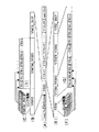
図5は、光ディスク2が何らファイルを記録していない、いわゆるブランクディスクの場合を例にとって、このINC方式によりビデオデータの記録処理の説明に供する図である。
【0065】
INC方式においては、一度に書き込むエリアは最大3つまでと定義されており、このエリアをそれぞれRzoneと呼び、各RzoneをRMAで管理する。
【0066】
システムコントローラ10は、図5(A)に示すように、光ディスク2より取得してメモリに保持したRMAの情報を更新することによりRzone1をリザーブする。さらに、RMAの情報を更新することによりRzone2及びInvisible Rzoneをリザーブし、実データであるビデオデータを順次Invisible Rzoneに記録してVTSTT_VOBSを生成する。
【0067】
すなわち、動画を記録する場合、INC方式においては、図5(A)に示すように、始めにRzoneをリザーブする。ここで、Rzoneのリザーブは、管理情報を記録する領域であるUDF領域A1及びVMG領域A2を形成するRzone1の領域を定義し、続いてVTS記録領域A3を形成する未記録領域に、先頭のVTSのVTSI、VTSM_VOBS、及び仮VMGI(TMP_VMGI:emporary Video Manager Information)を記録するRzone2の領域を定義し、残る未記録領域をInvisible Rzoneの領域と定義して、実行される。
【0068】
そして、INC方式においては、Invisible Rzoneの先頭側より順次動画を記録することにより、実データによるVTSTT_VOBSを形成する。さらにユーザーの指示により、1つのVTSについて実データの記録が完了すると、図5(B)に示すように、この実データの記録に続いてVTSI_BUPを記録し、また、図5(C)に示すように、先頭側に戻ってRzone2にVTSI及びTMP_VMGIを形成し、Rzone2を閉じる。図示はしないがオプションであるVTSM_VOBSが必要な場合は、この領域に記録する。また、上記VTSのVTSI、VTSM_VOBS、TMP_VMGIに対応するように、管理用情報をメモリに記録し、メモリに保持したRMAの情報を更新する。INC方式においては、このようにして先頭のVTS#1を光ディスクに記録する。
【0069】
続けて次のVTS#2を記録する場合、INC方式においては、システムコントローラ10は、同様にメモリに保持したRMAの情報を更新して、図5(D)に示すように、残りの未記録領域にRzone3をリザーブしてVTSI、VTSM_VOBS、及びTMP_VMGIの領域を確保し、Invisible Rzoneを定義する。さらに続いて、図5(E)に示すように、実データの記録によりVTSTT_VOBSを形成した後、VTSI_BUPを形成し、図5(F)に示すように、先に確保した領域にVTSI、VTSM_VOBS、及びTMP_VMGIを記録する。これにより光ディスクでは、図5(G)に示すように、続くVTS#2が記録される。
【0070】
INC方式においては、引き続きVTSを記録する場合、同様に未記録領域を定義して順次VTSが記録される。
【0071】
これによりシステムコントローラ10は、INC方式により順次タイトルを記録するようになされている。また、未だファイナライズされていない光ディスク2が装填され、この光ディスク2に動画を追記する場合には、図3のステップSP1で取得したRMAのデータであって、メモリに保持してあるRMAのデータにより、既に記録済のタイトルの末尾より、同様の処理を実行し、これにより撮像結果である動画を追記する。
【0072】
このようしてINC方式でVTSが順次記録され、VTS記録領域A3が形成された光ディスクは、ファイナライズ処理等によるフォーマット変換を行わなければ、DVD−Videoフォーマットに対応する再生装置等で再生することができない。
【0073】
ここで、図5(H)を用いて、ファイナライズ処理について説明する。
【0074】
例えば、光ディスクは、最後にDVD−Videoフォーマットに合致させるため、記録最終位置を内周から70mmに合うようにパディングライトを行った後、図5(H)に示すように、ファイナライズ処理によりRzone1にUDF領域A2及びVMG領域A3が形成され、最内周にリードイン(Lead In)領域が形成され、最外周にリードアウト(Lead Out)領域が形成される。このファイナライズ処理により、再生専用の光ディスクDVD-ROMに使用されるDVD−Videoフォーマットとの互換性を確保することができる。なお、このUDF領域A1及びVMG領域A2の形成においては、TMP_VMGIのデータより、UDF領域A1及びVMG領域A2に記録するデータを生成し、このデータをRzone1に記録してRzone1を閉じる作業が行われる。
【0075】
すなわち、ファイナライズ処理においては、図5(H)に示すように、このようにして生成してメモリに保持した管理用情報によりRzone1のUDF及びVMGを生成し、リードイン及びリードアウトを生成する。なお、未だファイナライズされていない光ディスク2に追記した場合には、既に光ディスク2に記録済のVTSについては、図3のステップSP2で取得したTMP_VMGIにより、これらVTSについてのUDF及びVMGのデータを生成することは、言うまでもない。
【0076】
これらにより、この光ディスク記録/再生装置100では、動画のファイルについては、INC方式を用いたDVD−Video Format Recordingにより記録するようになされている。
【0077】
ここで、この光ディスク記録/再生装置100におけるファイナライズ処理について説明する。
【0078】
この光ディスク記録/再生装置100では、ファイナライズ処理をいくつかの処理に分割し、1つの処理の終了毎にその旨をフラッシュメモリ16に記憶しておき、また、処理毎の開始前に電池の残量を確認して、その電池残量で今から行おうとする処理が終了するか判断し、処理が終了しそうにない場合は充電された電池に交換されるまで一切の処理を禁止しておき、十分に容量のある電池に交換されたとき、これを検出して、フラッシュメモリ16に記録された処理以降からファイナライズを再開する。
【0079】
これにより、ファイナライズ途中で電池がなくなったとしても、ファイナライズを再開することで完全なDVD−Videoフォーマットに合致したメディアとすることができる。
【0080】
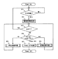
ユーザーがファイナライズを指示して以降の処理に注目すると、その大まかな処理手順は、図6のフローチャートに示すようにステップS1〜S4を有するものとなる。
【0081】
ステップS1では、70mmパディング処理を行う。
【0082】
ステップS2では、UDFを作成処理を行う。
ステップS3では、VMGを作成処理を行う。
ステップS4では、Lead In/Lead Outの書き込み処理を行う。
【0083】
なお、ファイナライズ処理前にファイナライズ処理を開始したことをフラッシュメモリ16に覚えておく(ステップS0)。これにより次回電源投入時、この値を参照することでファイナライズ処理中であったかどうかを判断することができる。また、ファイナライズ処理の最後では必ずファイナライズ処理が完全に終了したことをフラッシュメモリ16に書き戻しておく(ステップS5)。
【0084】
さらに、これらのそれぞれの処理の間に、その処理が終了したことをフラッシュメモリ16に格納するとともに、電池の残容量を確認する。このとき電池の容量が次の処理を行うだけの容量残っていれば次のステップに進み、そうでない場合はユーザーに電池の交換を促し、電源をOFFする。さらに次回電源ONではフラッシュメモリ16の内容を確認することで、ファイナライズが上記のいずれのステップまで終了したかを認識し、その次のステップからファイナライズ処理を再開する。
【0085】
70mmパディング処理は、例えば1ECCブロック毎に分割し記録最終位置が内周から70mmを超えるまで繰り返し行われる。このとき、1ECCブロックの処理が終了するその旨をフラッシュメモリ16に格納するとともに、電池の残容量を確認する。ここで、電池の残容量が一定量以下であれば、この段階でファイナライズを中断する。
【0086】
上記ステップS1の70mmパディング処理は、図7のフローチャートに示す手順に従って実行される。
【0087】
すなわち、上記ステップS1の70mmパディング処理が指示されると、先ず、フラッシュメモリ16に格納されている情報を参照して、70mmパディングが必要か否かを判定する(ステップS10)。
【0088】
このステップS10における判定の結果、70mmパディング処理の要/不要を示す情報はフラッシュメモリ16に格納されていない場合には、記録最終位置に基づいて70mmパディングが必要か否かを判定して(ステップS10A)、70mmパディング処理の要/不要を示す情報をフラッシュメモリ16に格納する(ステップS10B,S10C)。
【0089】
上記ステップS10における判定の結果、70mmパディングが必要である場合には、ステップS11に進む。
【0090】
また、上記ステップS10における判定の結果、記録最終位置がディスク内周から70mmに達しており、70mmパディングが不要である場合には、そのまま70mmパディング処理を行うことなく、処理を終了とする。
【0091】
ステップS11では、70mmパディングを開始しているか否かをフラッシュメモリ16に格納されている情報に基づいて判定する。
【0092】
このステップS11の判定結果がNOすなわち70mmパディングが開始されていない場合には、70mmパディングが開始されたことを示す情報をフラッシュメモリ16へ格納し(ステップS12)、フラッシュメモリ16上の書き込み位置を初期化して(ステップS13)、ステップS15に進む。
【0093】
また、上記ステップS11の判定結果がYESすなわち70mmパディングが既に開始されている場合には、70mmパディングが終了しているか否かをフラッシュメモリ16に格納されている情報に基づいて判定する(ステップS14)。
【0094】
そして、このステップS14の判定結果がNOすなわち70mmパディングが終了していない場合にはステップS15に進み、また、判定結果がYESすなわち70mmパディングが終了している場合には、70mmパディング処理を終了する。
【0095】
ステップS15では、記録最終位置をディスク内周から70mm内にあるかフラッシュメモリ16に格納されている情報に基づいて否かを判定する。
【0096】
そして、このステップS15における判定結果がNOすなわち、記録最終位置をディスク内周から70mm内にある場合には、電池の残容量が一定量以上あるか否かを判定して(ステップS16)、その判定結果がNOすなわち電池の残容量が一定量未満のときには、この段階でファイナライズを中断する。
【0097】
そして、上記ステップS16における判定結果がYESすなわち電池の残容量がパディングライトを行うのに必要な一定量以上あればパディングライトを行い(ステップS17)、フラッシュメモリ16の書き込み位置を更新して(ステップS18)、上記ステップS15の判定処理に戻って、記録最終位置が内周から70mmを超えるまでパディングライトを行い繰り返し行う。
【0098】
また、上記ステップS15における判定結果がYESすなわち、記録最終位置をディスク内周から70mmに達した場合には、70mmパディングが終了したことを示す情報をフラッシュメモリ16に格納して(ステップS19)、上記ステップS1の70mmパディング処理を終了する。
【0099】
また、上述のステップS2のUDFの作成処理は、分割できないので、図8のフローチャートに示すように、一気に行う。
【0100】
すなわち、UDFの作成処理では、先ず、フラッシュメモリ16に格納されている情報に基づいて、UDFの作成を終了しているか否かを判定し(ステップS21)、その判定結果がNOすなわちUDFの作成が終了している場合には、そのまま処理を終了とする。
【0101】
また、上記ステップS21の判定結果がNOすなわちUDFを作成する必要がある場合には、UDFの書き込みを行う前に電池の残容量がUDFの書き込みに必要な所定量以上あるか否かを判定する(ステップS22)。
【0102】
上記ステップS22における判定結果がNOすなわち電池の残容量がUDFの書き込みを行うのに十分でないときには、この段階でファイナライズを中断する。
【0103】
また、上記ステップS22における判定結果がYESすなわち電池の残容量がUDFの書き込みを行うのに十分ある場合に、UDFを作成し(ステップS23)、UDFの作成が終了したことを示す情報をフラッシュメモリ16に格納して(ステップS24)、上述のステップS2のUDFの作成処理を終了する。
【0104】
また、上述のステップS3のVMGの作成処理は、図9のフローチャートに示すように、VMGIの作成及び書き込み処理(ステップS31)、VMGM_VOBSの作成及び書き込み処理(ステップS32)及び VMGI_BUPの書き込み処理(ステップS33)からなる。
【0105】
ここで、それぞれの処理を実行する前に電池の残容量を確認し、その容量がその処理の終了までに十分でなければ、その段階でファイナライズを中断する。容量が十分あればその処理を実行し、その旨をフラッシュメモリ16に格納しておく。
【0106】
VMGIの作成及び書き込み処理(ステップS31)では、先ず、フラッシュメモリ16に格納されている情報に基づいて、VMGIの作成を終了しているか否かを判定し(ステップS31A)、その判定結果がNOすなわちVMGIを作成する必要がある場合には、VMGIの書き込みを行う前に電池の残容量がVMGIの書き込みに必要な所定量以上あるか否かを判定する(ステップS31B)。
【0107】
上記ステップS31Bにおける判定結果がNOすなわち電池の残容量がVMGIの書き込みを行うのに十分でない場合には、この段階でファイナライズ処理を中断する。
【0108】
上記ステップS31Bにおける判定結果がYESすなわち電池の残容量がVMGIの書き込みを行うのに十分ある場合には、VMGIを作成し(ステップS31C)、VMGIの作成が終了したことを示す情報をフラッシュメモリ16に格納して(ステップS31D)、VMGM_VOBSの作成及び書き込み処理(ステップS32)に進む。
【0109】
また、上記ステップS31Aの判定結果がYESすなわちVMGIの書き込みが終了している場合には、VMGM_VOBSの作成及び書き込み処理(ステップS32)に進む。
【0110】
VMGM_VOBSの作成及び書き込み処理(ステップS32)では、先ず、フラッシュメモリ16に格納されている情報に基づいて、VMGM_VOBSの作成を終了しているか否かを判定し(ステップS32A)、その判定結果がNOすなわちVMGM_VOBSを作成する必要がある場合には、VMGM_VOBSの書き込みを行う前に電池の残容量がVMGM_VOBSの書き込みに必要な所定量以上あるか否かを判定する(ステップS32B)。
【0111】
上記ステップS32Bにおける判定結果がNOすなわち電池の残容量がVMGM_VOBSの書き込みを行うのに十分でない場合には、この段階でファイナライズ処理を中断する。
【0112】
上記ステップS32Bにおける判定結果がYESすなわち電池の残容量がVMGM_VOBSの書き込みを行うのに十分ある場合に、N枚目のVMGM_VOBS用メニュー画面N枚目の作成して書き込む(ステップS32C)、N枚目のVMGM_VOBS用メニュー画面の作成が終了したことを示す情報をフラッシュメモリ16に格納して(ステップS32D)、最後のメニューの作成が終了したか否かを判定する(ステップS32E)。
【0113】
そして、上記ステップS32Eの判定結果がNOすなわち作成すべきVMGM_VOBS用メニュー画面がある場合には、上記ステップS32Bに戻って、電池の残容量が次のVMGM_VOBSの書き込みを行うのに十分ある場合に次のVMGM_VOBS用メニュー画面を作成して記録するという処理を繰り返し行い、上記ステップS32Eの判定結果がYESすなわち最後のメニューの作成を終了したら、VMGI_BUPの書き込み処理(ステップS33)に進む。
【0114】
VMGI_BUPの書き込み処理(ステップS33)では、先ず、フラッシュメモリ16に格納されている情報に基づいて、VMGI_BUPの書き込みを終了したか否かを判定し(ステップS33A)、その判定結果がYESすなわちVMGM_VOBSの書き込みを終了している場合には、そのまま処理を終了する。
【0115】
また、上記ステップS33Aの判定結果がNOすなわちVMGM_VOBSを作成する必要がある場合には、VMGI_BUPの書き込みを行う前に電池の残容量がVMGI_BUPの書き込みに必要な所定量以上あるか否かを判定する(ステップS33B)。
【0116】
上記ステップS33Bにおける判定結果がNOすなわち電池の残容量がVMGI_BUPの書き込みを行うのに十分でない場合には、この段階でファイナライズ処理を中断する。
【0117】
上記ステップS33Bにおける判定結果がYESすなわち電池の残容量がVMGI_BUPの書き込みを行うのに十分である場合に、VMGI_BUPを作成して書き込み(ステップS33C)、VMGI_BUの書き込みが終了したことを示す情報をフラッシュメモリ16に格納して(ステップS33D)、上述のステップS3のVMGの作成処理を終了する。
【0118】
さらに、上述のステップS4のLead In/Lead Outの書き込み処理は、分割できないので、図10のフローチャートに示すように、一気に行う。
【0119】
すなわち、Lead In/Lead Outの書き込み処理では、先ず、フラッシュメモリ16に格納されている情報に基づいて、Lead In/Lead Outの書き込みを終了しているか否かを判定し(ステップS41)、その判定結果がNOすなわちLead In/Lead Outの書き込みを終了している場合には、そのまま処理を終了とする。
【0120】
そして、上記ステップS41の判定結果がNOすなわちLead In/Lead Outの書き込み行う必要がある場合には、Lead In/Lead Outの書き込みを行う前に電池の残容量がLead In/Lead Outの書き込みに必要な所定量以上あるか否かを判定する(ステップS42)。
【0121】
上記ステップS42における判定結果がNOすなわち電池の残容量がUDFの書き込みを行うのに十分でないときには、この段階でファイナライズを中断する。
【0122】
そして、上記ステップS42における判定結果がYESすなわち電池の残容量がLead In/Lead Outの書き込みを行うのに十分ある場合に、Lead In/Lead Outを書き込み(ステップS43)、Lead In/Lead Outの書き込みが終了したことを示す情報をフラッシュメモリ16に格納して(ステップS43)、上述のステップS4のLead In/Lead Outの書き込み処理を終了する。
【0123】
図11は、以上のようにしてビデオデータを光ディスク2に記録する上記光ディスク記録/再生装置100における再生処理の手順を示すフローチャートである。システムコントローラ10は、この再生処理手順を開始すると、ステップSP31において、システムコントローラ10は、ユーザーにより再生の開始が指示されたか否か判断する。ここで否定結果が得られると、システムコントローラ10は、ステップSP31を繰り返すのに対し、肯定結果が得られると、ステップSP31からステップSP32に移る。ここで、システムコントローラ10は、フラッシュメモリ16に記録して保持した管理用情報を基準にして、ユーザーにより指示された画像のファイルを再生するように全体の動作を制御する。
【0124】
すなわち、光ディスク2がファイナライズ処理された光ディスクの場合、フラッシュメモリ16に保持したVMGのデータにより対応するタイトルの再生位置を検出し、この再生位置からの再生を光ディスク記録/再生装置100の各部に指示する。これに対して光ディスク2がファイナライズ処理されていない光ディスクの場合、フラッシュメモリ16に保持したTMP_VMGI及び各タイトルのVTSI、VTSTT_VOBSにより対応するタイトルの再生位置を検出し、この再生位置からの再生を光ディスク記録/再生装置100の各部に指示する。
【0125】
このように再生を指示すると、システムコントローラ10は、続いてステップSP33に移り、ユーザーにより再生の停止が指示されたか否か判断し、ここで否定結果が得られると、ステップSP32に戻る。これによりシステムコントローラ10は、ステップSP32−SP33−SP32の処理手順を繰り返し、順次、ユーザーにより指示された動画のファイルを再生する。これに対してステップSP33で肯定結果が得られると、再生の動作を終了し、この再生処理手順を終了する。
【0126】
なお、以上の説明では、DVD−RにINC方式でビデオデータを記録する場合について述べたが、DVD−RWでROW方式によりビデオデータを記録するようにしてもよい。
【0127】
ROW方式によるDVD−Video Format Recordingの記録手順を図12に示す。ROW方式においては、図12(A)に示すように、リードイン、UDF領域、VMG領域、先頭VTSのVTSI及びVTSM_VOBSの記録領域をパディング(Padding)により事前に確保する。ここでパディングとは、NULL等のダミーデータを記録して領域を確保する処理のことである。
【0128】
このようにしてこれらの領域を確保すると、ROW方式においては、図12(B)に示すように、順次画像を記録することにより、実データによるVTSTT_VOBSが形成され、1つのVTSについて実データの記録が完了すると、続いてVTSI_BUPが記録され、さらに続くVTSのVTSI及びVTSM_VOBSの記録領域の確保のために、パディングの処理が実行される。また、続いて先頭側に戻って、図12(C)に示すように、この実データの記録に対応するVTSI及びVTSM_VOBSが形成される。さらに、TMP_VMGIをUDF用領域とVMG用領域の間に記録する。この時点で第1のタイトル(VTS#1)が完成する。このようにしてROW方式においては、1つのVTS#1が光ディスクに記録される。
【0129】
また、続けて次のVTSを記録する場合、ROW方式においては、図12(D)に示すように、直前のVTSにより形成したパディングの領域に続いて、実データが記録されることによりVTSTT_VOBS及びVTSI_BUPが形成され、続くVTSのVTSI及びVTSM_VOBSの記録領域の確保のために、パディングの処理が実行される。また、続いて、図12(E)に示すように、VTSI及びVTSM_VOBSが形成され、さらに、UDF用領域とVMG用領域の間のTMP_VMGIを上書きする。この時点で第2のタイトル(VTS#2)が完成する。このようにしてROW方式においては、図12(F)に示すように、続くVTS#2が光ディスクに記録される。
【0130】
ROW方式においては、引き続きVTSを記録する場合、同様にパディング等の処理が実行されて順次VTSが記録される。
【0131】
ここで、上記ROW方式でVTSが順次記録され、VTS記録領域A3が形成された光ディスクは、図6〜図10を参照して説明したINC方式と同様なファイナライズ処理によるフォーマット変換を行うことにより、DVD−Videoフォーマットにのみ対応する再生装置等で再生することができる。
【0132】
すなわち、ファイナライズ処理では、図12(G)に示すように、DVD−Videoフォーマットに合致させるため、記録最終位置を内周から70mmにあうようにパディングライトを行った後、各タイトルの管理情報からUDF及びVMGを作成し、最初にパディングしたUDF領域、VMG領域に記録することによりUDF領域及びVMG領域が形成され、さらに、最内周にリードイン情報を記録することによりリードイン(Lead In)領域が形成され、最外周にリードアウト情報を記録するによりリードアウト(Lead Out)領域が形成される。
【0133】
このファイナライズ処理の施された光ディスクは、再生専用の光ディスクDVD−ROMで使用されるDVD−Videoフォーマットとの互換性を確保ことができる。
【0134】
【発明の効果】
以上詳細に説明したように、本発明によれば、ファイナライズ処理をいくつかの処理に分割し、1つの処理の終了毎にその旨を不揮発性のメモリに記憶しておき、また、処理毎の開始前に電池の残量を確認して、その電池残量で今から行おうとする処理が終了するか判断し、処理が終了しそうにない場合は充電された電池に交換されるまで一切の処理を禁止しておき、十分に容量のある電池に交換されたとき、これを検出して、不揮発性メモリに記録された処理以降からファイナライズを再開することにより、ファイナライズ途中で電池がなくなったとしても、ファイナライズを再開することで完全なDVD−Videoフォーマットに合致したメディアとすることができる。すなわち、ファイナライズの途中で電池の残量がたりなくなっても十分に容量のある電池に入れ替えることでファイナライズを再開することにより、追記も再生もできない中途半端な状態のメディアになることを防ぐことができる。
【図面の簡単な説明】
【図1】本発明を適用した光ディスク記録/再生装置の構成を示すブロック図である。
【図2】DVD−ビデオフォーマットの説明に供する図である。
【図3】上記光ディスク記録/再生装置において電源の立ち上げ時に実行される処理の手順を示すフローチャートである。
【図4】上記光ディスク記録/再生装置における画像ファイルの記録処理の手順を示すフローチャートである。
【図5】上記光ディスク記録/再生装置におけるINC方式による動画ファイルの記録処理の説明に供する図である。
【図6】上記光ディスク記録/再生装置におけるファイナライズ処理の概要を示すフローチャートである。
【図7】上記ファイナライズ処理における70mmパディング処理の手順を示すフローチャートである。
【図8】上記ファイナライズ処理におけるUDFの作成処理の手順を示すフローチャートである。
【図9】上記ファイナライズ処理におけるVMGの作成処理の手順を示すフローチャートである。
【図10】上記ファイナライズ処理におけるLead In/Lead Outの書き込み処理の手順を示すフローチャートである。
【図11】上記光ディスク記録/再生装置における画像ファイルの再生処理の手順を示すフローチャートである。
【図12】上記光ディスク記録/再生装置におけるROW方式による動画ファイルの記録処理の説明に供する図である。
【符号の説明】
2 光ディスク、3 映像入力部、5 オーディオ入力部、6 圧縮/伸長処理部、7 ヘッダー情報処理部、9,15,22 ランダムアクセスメモリ、10 システムコントローラ、11 操作部、12 モニタ部、13 ビデオ/オーディオエンコーダ、14 DVD信号処理部、16 フラッシュメモリ、17アナログフロントエンド部、18 モータ駆動制御部、19 光学ヘッド、20 スピンドルモータ、21 スレッドモータ、61 ビデオ処理部、62 オーディオ処理部、63 多重化処理部、100 光ディスク記録/再生装置[0001]
BACKGROUND OF THE INVENTION
The present invention relates to an optical disk recording apparatus and method for recording data on an optical recording medium capable of recording and reproducing data such as DVD-R (DVD Recordable) or DVD-RW (DVD Re-recordable).
[0002]
[Prior art]
Currently, DVD-R (DVD Recordable) capable of recording data and DVD-RW (DVD Re-recordable) capable of rewriting recorded data in a DVD (Digital Versatile Disc) which is one of large-capacity optical disks. In addition, DVD-RAM (DVD Random Access Memory) and the like are provided. Data recorded on a DVD-R or DVD-RW cannot be played back because the format is incompatible with a playback device, a PC (personal computer), or the like that supports only the DVD-Video format. In order to reproduce data recorded on a DVD-R or DVD-RW or the like (hereinafter referred to as DVD-R / -RW) with the above-described reproducing apparatus or PC, the data recorded on the DVD-R / -RW is recorded on a DVD. -It is necessary to convert to a predetermined format conforming to the Video format. In order to play back data recorded on a DVD-R / -RW with a PC or the like, it is necessary to conform the data recorded on the DVD-R / -RW to the Universal Disk Format (UDF) standard. is there.
[0003]
As a recording method for writing a moving image on such an optical disc, there is an incremental recording method (hereinafter referred to as an INC method) or a restricted overwrite method (hereinafter referred to as a ROW method). The INC method is mainly used for DVD-R and the like, and is a method for recording moving images sequentially. The ROW method is mainly used for DVD-RW and the like, and is a method for recording moving images at random. is there. However, even in the ROW method, when data is recorded in an unrecorded area, it is necessary to record a moving image sequentially. In these INC system and ROW system, RMA (Recording Management Area) provided on the inner circumference side from the lead-in holds the recording management information of the entire optical disk such as recording area reservation and next recording address. Has been made.
[0004]
[Problems to be solved by the invention]
By the way, in both the INC system and the ROW system as described above, finalization processing is necessary to ensure compatibility with a reproduction-only optical disk.
[0005]
However, during this finalizing process, it takes time for finalizing process to record padding light up to 70 mm, VMG creation from each title management information, lead-in, lead-out, and the like. At this time, when considering a battery-operated system such as a portable device, if the battery runs out during finalization, the media is in an intermediate state that is neither in an intermediate state that can be appended nor finalized. There was a problem that the recording / reproduction was hindered.
[0006]
In view of the above-described problems, an object of the present invention is to provide an optical recording method and an optical recording apparatus capable of reliably performing a finalizing process on an optical recording medium.
[0007]
[Means for Solving the Problems]
The present inventionThe data zone is divided into a first management information area that is a file system area, a second management information area that records a reproduction management system for real-time data recorded in the data area, and a data area that records real-time data.An optical recording method in a recording apparatus for recording data on an optical recording medium,
Finalization processA file system including padding processing for performing padding recording to a predetermined final recording position, reproduction management information recorded in the second management information area, and information for managing the entire real-time data recorded in the data area. Includes first management information processing created in a format ensuring compatibility with the file system and recorded in the first management information area, and reproduction management information for reproducing and managing the entire real-time data recorded in the data area Each time the reproduction management information is created by dividing the second management information processing for creating the reproduction management system and recording it in the second management information area and the writing process for the lead-in area and the lead-out area, Check the remaining battery level before starting the process to write the created playback management information, and the write process to be executed with that remaining battery charge will end. If the remaining battery level is sufficient, the writing process is executed, and that fact is stored in the non-volatile memory every time one playback management information writing process is completed, and the remaining battery level is sufficient. Otherwise, the finalizing process is interrupted in the writing process, and the finalizing process is resumed from the writing process recorded in the non-volatile memory when the remaining battery level becomes sufficient.
It is characterized by that.
[0008]
Also,The present invention provides a first management information area whose data zone is a file system area, a second management information area for recording a reproduction management system for real-time data recorded in the data area, and a data area for recording real-time data A recording apparatus for recording data on an optical recording medium classified into: a finalizing process, a padding process for performing padding recording to a predetermined final recording position, and a reproduction recorded in the second management information area A file system including management information and information for managing the entire real-time data recorded in the data area is created in a format ensuring compatibility with other file systems and recorded in the first management information area Management information processing and playback management information that plays back and manages the entire real-time data recorded in the data area Is divided into a second management information processing for creating a reproduction management system including the above and recording it in the second management information area, and a writing process for the lead-in area and the lead-out area. Check the remaining battery level, determine whether the process to be executed with the remaining battery level is completed, and execute the process when the remaining battery level is sufficient. If the remaining battery level is not sufficient, the finalizing process is interrupted in that process, and when the remaining battery level becomes sufficient, the finalizing process is started after the process recorded in the non-volatile memory. Each time the playback management information is created, the control means checks the remaining battery level before starting the process of writing the created playback management information, and executes the remaining battery level. Writing When the remaining battery level is sufficient, the writing process is executed, and that information is stored in the non-volatile memory every time one playback management information writing process is completed. When the remaining amount is not enough, the finalizing process is interrupted in the writing process, and when the remaining battery level becomes sufficient, the finalizing process is restarted after the process recorded in the nonvolatile memory. And
[0013]
DETAILED DESCRIPTION OF THE INVENTION
Hereinafter, embodiments of the present invention will be described in detail with reference to the drawings.
[0014]
The present invention is applied to, for example, an optical disc recording / reproducing
[0015]
The optical disc recording / reproducing
[0016]
An optical disk recording / reproducing
[0017]
This optical disk recording /
[0018]
The optical disc recording / reproducing
[0019]
In the optical disc recording / reproducing
[0020]
The
[0021]
The operation of the compression / decompression processing unit 6 is switched under the control of the system controller 10, and at the time of recording, the random access memory 9 is used to compress and multiplex video data and audio data, and the header information processing unit 7 Output to. During reproduction, the random access memory 9 is used to separate the data obtained from the header information processing unit 7 into video data and audio data, and then the data is decompressed and output to the
[0022]
That is, in the compression / decompression processing unit 6, the
[0023]
Also, the
[0024]
The
[0025]
The video /
[0026]
The header information processing unit 7 receives time-division multiplexed data output from the compression / decompression processing unit 6 at the time of recording, and adds header information unique to the DVD, header information of the extension file, and the like under the control of the system controller 10 And output. Further, based on information from the system controller 10, data such as UDF, VMG, and VTSI is generated and output to the DVD
[0027]
The system controller outputs the reproduction management information stored in the
[0028]
Further, at the time of reproduction, the DVD
[0029]
The analog
[0030]
Further, the analog
[0031]
The motor
[0032]
The
[0033]
The
[0034]
The system controller 10 includes a computer that controls the operation of the entire optical disc recording / reproducing
[0035]
Here, an outline of the DVD-Video format is shown in FIG.
[0036]
FIG. 2 is a diagram showing an outline of the data structure of an optical disc in which data is recorded by the DVD-Video Format Recording method, which is a logical format compliant with the DVD-Video format. On the information recording surface of the optical disc corresponding to the DVD-Video format, the information recorded on the spiral is schematically shown in a band shape as shown in FIG. A lead-in area indicating the start of recording, a data zone, and an information lead-out area are allocated to the outermost periphery. Desired actual data is recorded in the data zone.
[0037]
Here, from the lead-in area side, the data zone is a UDF (Universal Disk Format) area A1 which is a file system area in which a UDF bridge configuration is described, a VMG (Video Manager) area A2 which is a DVD management information area, and real-time data. Are recorded in a VTS (Video Title Set) area A3.
[0038]
The UDF area A1 and the VMG area A2 are areas for recording information for managing video data recorded in the VTS area A3. The UDF area A1 is called a first management information area, and the VMG area A2 is called a second management information area. The VMG area A2, which is the second management information area, is an area corresponding to a reproduction management system specific to the DVD-Video format, and information for reproducing and managing the entire video data recorded in the VTS recording area A3 is recorded. . On the other hand, the UDF area A1, which is the first management information area, is an area corresponding to a file management system such as a PC, and VMG has a format such as UDF for ensuring compatibility with the file system on the PC. Playback management information recorded in the area A2 and information for managing the entire video data recorded in the VTS recording area A3 are recorded. Thereby, information for searching for the head of the VMG area A2 is also included in the UDF area A1.
[0039]
Further, as shown in FIG. 2B, the VMG includes a VMGI (Video Manager Information), a VMGM_VOBS (Video Object Set for Video Manager Menu), and a VMGI_BUP for backup.
[0040]
The VMGI is control information for the entire DVD video zone, and includes a VMGM_PGCI (VMG Menu Program Chain Information) group having links to the respective VTS menus as shown in FIG.
[0041]
VMGM_VOBS is video information for a title selection menu, and as shown in FIG. 2D, each is composed of a plurality of CELLs corresponding to the title menu. VMGI_BUP is a complete copy of VMGI.
[0042]
As shown in FIG. 2 (E), the VTS has VTSI (Video Title Set Information), VTSM_VOBS (Video Object Set for the VTS Menu), VTSTT_VOBS (Video Object Set for Titles in a VTS), and VTSI_BUP ( Backup of VTSI).
[0043]
The control information of each VTS is stored in the VTSI. As shown in FIG. 2F, a VTSM_PGCI (VTS Menu Program Chain Information) group having a link to a delimiter in each VTSM_VOBS and a delimiter in each VTSTT_VOBS VTS_PGCI (VTS Program Chain Information) group having a link to
[0044]
As shown in FIG. 2G, the TSM_VOBS (Video Object Set For Video Title Set Menu) is composed of a plurality of CELLs, each corresponding to each page of the root menu screen. Note that VTSM_VOBS is an option.
[0045]
In the VTSTT_VOBS area, video data in the format of MPEG (Moving Picture Experts Group) 2 which is actual data, that is, video data as actual content is formed by packetized data for each predetermined amount. As shown in (G), it is stored as a set of a plurality of CELLs.
[0046]
The VTSI_BUP area is an area where VTSI backup data is recorded.
[0047]
When accessing the optical disk having the above-described data structure by a PC or the like, a desired file can be searched for and reproduced by the UDF area A1, and when reproduced by a DVD player, the VMG area is obtained by the UDF area A1. Is searched for, and a desired title can be searched and reproduced based on the information in the VMG area A2.
[0048]
Already widely used DVD playback machines can correctly play back as long as the above-described structure is satisfied. A recordable medium can be played back by a playback-only machine by recording in a procedure capable of constructing the above-described structure on a recordable or overwritable medium such as a DVD-R / DVD-RW. In other words, during recording, the above structure is recorded so that it can be constructed, and finalization is performed at the end of recording, so that it is completely matched with the DVD-Video format, so that it can also be played back on an existing DVD player. Create possible media. This recording method is called DVD-Video Format Recording.
[0049]
The optical disc recording / reproducing
[0050]
When the power is turned on, the system controller 10 determines the presence / absence of the
[0051]
In step SP2, the system controller 10 drives the
[0052]
Here, TMP_VMGI will be described. TMP_VMGI is a temporary VMGI that is recorded together with VTSI at the time when recording of one VTS is completed. Information on the number of VTSs and disk names recorded on the
[0053]
In this process, the system controller 10 acquires UDF data in addition to VMG data. When intermediate management information is recorded in the reproduction of the VTS recording area A3, this intermediate management information is also acquired. As a result, the system controller 10 can also acquire management information of the extension file so that the extension file not defined in the DVD-video format can be reproduced from the
[0054]
Subsequently, the system controller 10 proceeds to step SP3, determines whether or not the user has instructed to eject the
[0055]
On the other hand, when an instruction other than the ejection of the
[0056]
On the other hand, if the operation by the user is an operation for instructing recording, the system controller 10 moves from step SP4 to step SP6, executes a recording processing procedure for recording video data on the
[0057]
On the other hand, when the operation by the user is an operation to turn off the power, the system controller 10 moves from step SP4 to step SP7, executes the power-off processing, and ends this processing procedure.
[0058]
The system controller 10 performs a recording process according to the procedure shown in the flowchart of FIG. When the
[0059]
In the recording processing procedure shown in the flowchart of FIG. 4, the system controller 10 first determines in step SP11 whether the user's recording instruction relates to image recording or finalization processing.
[0060]
If the recording instruction by the user is related to image recording, the system controller 10 proceeds to step SP12 and determines whether or not the user has instructed to start recording. If a negative result is obtained here, the system controller 10 repeats step SP12, whereas if a positive result is obtained, the system controller 10 moves from step SP12 to step SP13 and records VTSTT_VOBS based on actual data.
[0061]
Further, the process proceeds to step SP14, where it is determined whether or not the user has instructed to stop recording. If a negative result is obtained, the process returns to step SP13. Thereby, the system controller 10 repeats the processing procedure of steps SP13-SP14-SP13, sequentially records the actual data, and when a positive result is obtained in step SP14, the recording of the actual data VTSTT_VOBS is completed.
[0062]
Subsequently, the system controller 10 proceeds to step SP15 to sequentially form VTSI_BUP, VTSI, and VTSM_VOBS, thereby recording one VTS, updating TMP_VMGI, and ending this recording processing procedure.
[0063]
On the other hand, when the recording instruction is related to the finalizing process by the user, the system controller 10 proceeds from step SP11 to step SP16 and determines whether or not the user has instructed the start of recording. If a negative result is obtained here, the system controller 10 repeats step SP16, whereas if a positive result is obtained, the system controller 10 proceeds from step SP16 to step SP17, executes finalization processing, and ends this processing procedure. .
[0064]
FIG. 5 is a diagram for explaining the video data recording process by the INC method, taking as an example a so-called blank disc in which no file is recorded on the
[0065]
In the INC system, it is defined that up to three areas are written at a time. Each of these areas is called Rzone, and each Rzone is managed by RMA.
[0066]
As shown in FIG. 5A, the system controller 10 reserves Rzone1 by updating RMA information acquired from the
[0067]
That is, when recording a moving image, in the INC method, as shown in FIG. 5A, Rzone is reserved first. Here, the Rzone reserve defines the RDF1 area that forms the UDF area A1 and the VMG area A2, which are areas for recording management information, and then the first VTS in the unrecorded area that forms the VTS recording area A3. This is executed by defining an Rzone2 area for recording VTSI, VTSM_VOBS, and temporary VMGI (TMP_VMGI: temporary Video Manager Information), and defining the remaining unrecorded area as an Invisible Rzone area.
[0068]
In the INC system, moving images are sequentially recorded from the head of the Invisible Rzone to form VTSTT_VOBS using actual data. Further, when the recording of actual data for one VTS is completed by the user's instruction, VTSI_BUP is recorded following the recording of the actual data as shown in FIG. 5B, and also shown in FIG. Thus, returning to the head side, VTSI and TMP_VMGI are formed in Rzone2, and Rzone2 is closed. Although not shown, when an optional VTSM_VOBS is required, it is recorded in this area. Also, management information is recorded in the memory so as to correspond to the VTSI, VTSM_VOBS, and TMP_VMGI of the VTS, and the RMA information held in the memory is updated. In the INC system, the
[0069]
When the
[0070]
In the INC method, when VTS is continuously recorded, VTSs are sequentially recorded by similarly defining an unrecorded area.
[0071]
As a result, the system controller 10 sequentially records titles by the INC method. Further, when an
[0072]
The optical disc on which the VTS is sequentially recorded by the INC method and the VTS recording area A3 is formed can be reproduced by a reproducing apparatus or the like corresponding to the DVD-Video format unless format conversion is performed by finalizing processing or the like. Can not.
[0073]
Here, the finalizing process will be described with reference to FIG.
[0074]
For example, the optical disc is padded and written so that the final recording position is 70 mm from the inner periphery in order to finally conform to the DVD-Video format. Then, as shown in FIG. A UDF region A2 and a VMG region A3 are formed, a lead-in region is formed on the innermost periphery, and a lead-out region is formed on the outermost periphery. By this finalizing process, compatibility with the DVD-Video format used for the reproduction-only optical disc DVD-ROM can be ensured. In the formation of the UDF area A1 and the VMG area A2, data to be recorded in the UDF area A1 and the VMG area A2 is generated from the TMP_VMGI data, and this data is recorded in Rzone1 to close Rzone1. .
[0075]
That is, in the finalizing process, as shown in FIG. 5H, the UDF and VMG of
[0076]
Thus, in the optical disc recording / reproducing
[0077]
Here, the finalizing process in the optical disc recording / reproducing
[0078]
In this optical disc recording / reproducing
[0079]
As a result, even if the battery runs out during finalization, by resuming finalization, it is possible to obtain a medium that conforms to the complete DVD-Video format.
[0080]
When a user pays attention to the subsequent processing after instructing finalization, the rough processing procedure includes steps S1 to S4 as shown in the flowchart of FIG.
[0081]
In step S1, a 70 mm padding process is performed.
[0082]
In step S2, UDF creation processing is performed.
In step S3, a VMG creation process is performed.
In step S4, a lead-in / lead-out write process is performed.
[0083]
Note that the
[0084]
Further, during each of these processes, the fact that the process has been completed is stored in the
[0085]
The 70 mm padding process is repeated, for example, for each ECC block until the final recording position exceeds 70 mm from the inner periphery. At this time, the fact that the processing of one ECC block is completed is stored in the
[0086]
The 70 mm padding process in step S1 is executed according to the procedure shown in the flowchart of FIG.
[0087]
That is, when the 70 mm padding process in step S1 is instructed, first, it is determined whether or not 70 mm padding is necessary with reference to the information stored in the flash memory 16 (step S10).
[0088]
If the result of determination in step S10 is that information indicating the necessity / unnecessity of 70 mm padding processing is not stored in the
[0089]
If 70 mm padding is necessary as a result of the determination in step S10, the process proceeds to step S11.
[0090]
If the final recording position has reached 70 mm from the inner periphery of the disc as a result of the determination in step S10 and 70 mm padding is not required, the processing is terminated without performing the 70 mm padding process.
[0091]
In step S11, it is determined based on information stored in the
[0092]
If the determination result in step S11 is NO, that is, if 70 mm padding has not started, information indicating that 70 mm padding has started is stored in the flash memory 16 (step S12), and the write position on the
[0093]
If the determination result in step S11 is YES, that is, if 70 mm padding has already been started, whether or not 70 mm padding has been completed is determined based on the information stored in the flash memory 16 (step S14). ).
[0094]
If the determination result in step S14 is NO, that is, if 70 mm padding is not completed, the process proceeds to step S15. If the determination result is YES, that is, 70 mm padding is completed, the 70 mm padding process is terminated. .
[0095]
In step S15, it is determined based on the information stored in the
[0096]
If the determination result in step S15 is NO, that is, if the final recording position is within 70 mm from the inner periphery of the disc, it is determined whether or not the remaining capacity of the battery is greater than a certain amount (step S16). If the determination result is NO, that is, if the remaining battery capacity is less than a certain amount, finalization is interrupted at this stage.
[0097]
If the determination result in step S16 is YES, that is, if the remaining capacity of the battery exceeds a certain amount necessary for padding write, padding write is performed (step S17), and the write position in the
[0098]
If the determination result in step S15 is YES, that is, if the final recording position has reached 70 mm from the inner circumference of the disc, information indicating that 70 mm padding has been completed is stored in the flash memory 16 (step S19). The 70 mm padding process in step S1 is completed.
[0099]
Further, since the UDF creation process in step S2 cannot be divided, it is performed at once as shown in the flowchart of FIG.
[0100]
That is, in the UDF creation process, first, based on the information stored in the
[0101]
If the determination result in step S21 is NO, that is, if it is necessary to create a UDF, it is determined whether or not the remaining capacity of the battery is greater than or equal to a predetermined amount required for UDF writing before UDF writing is performed. (Step S22).
[0102]
When the determination result in step S22 is NO, that is, when the remaining capacity of the battery is not sufficient for writing UDF, finalization is interrupted at this stage.
[0103]
If the determination result in step S22 is YES, that is, if the remaining battery capacity is sufficient to write UDF, UDF is created (step S23), and information indicating that creation of UDF is completed is stored in the flash memory. 16 (step S24), and the UDF creation process in step S2 is terminated.
[0104]
Further, the VMG creation process in step S3 described above includes the VMGI creation and write process (step S31), the VMGM_VOBS creation and write process (step S32), and the VMGI_BUP write process (step S31), as shown in the flowchart of FIG. S33).
[0105]
Here, the remaining capacity of the battery is confirmed before executing each process, and if the capacity is not sufficient by the end of the process, finalization is interrupted at that stage. If the capacity is sufficient, the process is executed and the fact is stored in the
[0106]
In the VMGI creation and writing process (step S31), first, based on the information stored in the
[0107]
If the determination result in step S31B is NO, that is, if the remaining battery capacity is not sufficient to write VMGI, the finalizing process is interrupted at this stage.
[0108]
If the determination result in step S31B is YES, that is, if the remaining capacity of the battery is sufficient to perform writing of VMGI, VMGI is created (step S31C), and information indicating that the creation of VMGI has ended is stored in
[0109]
On the other hand, if the determination result in step S31A is YES, that is, the writing of VMGI has ended, the process proceeds to VMGM_VOBS creation and writing processing (step S32).
[0110]
In the VMGM_VOBS creation and writing process (step S32), first, based on the information stored in the
[0111]
If the determination result in step S32B is NO, that is, if the remaining battery capacity is not sufficient for writing VMGM_VOBS, the finalizing process is interrupted at this stage.
[0112]
If the determination result in step S32B is YES, that is, if the remaining capacity of the battery is sufficient to write VMGM_VOBS, the Nth VMGM_VOBS menu screen is created and written (step S32C). Information indicating that the creation of the VMGM_VOBS menu screen has been completed is stored in the flash memory 16 (step S32D), and it is determined whether or not the creation of the last menu has been completed (step S32E).
[0113]
If the determination result in step S32E is NO, that is, if there is a VMGM_VOBS menu screen to be created, the process returns to step S32B, and if the remaining battery capacity is sufficient to write the next VMGM_VOBS, The process of creating and recording the VMGM_VOBS menu screen is repeatedly performed, and if the determination result in step S32E is YES, that is, the creation of the last menu is completed, the process proceeds to the VMGI_BUP writing process (step S33).
[0114]
In the VMGI_BUP write process (step S33), first, based on the information stored in the
[0115]
If the determination result in step S33A is NO, that is, if VMGM_VOBS needs to be created, it is determined whether or not the remaining capacity of the battery is greater than or equal to a predetermined amount necessary for writing VMGI_BUP before writing VMGI_BUP. (Step S33B).
[0116]
If the determination result in step S33B is NO, that is, if the remaining battery capacity is not sufficient for writing VMGI_BUP, the finalizing process is interrupted at this stage.
[0117]
If the determination result in step S33B is YES, that is, if the remaining battery capacity is sufficient to write VMGI_BUP, VMGI_BUP is created and written (step S33C), and information indicating that the writing of VMGI_BU is completed is flashed The process is stored in the memory 16 (step S33D), and the VMG creation process in step S3 described above is terminated.
[0118]
Further, since the write processing of Lead In / Lead Out in step S4 cannot be divided, it is performed at a time as shown in the flowchart of FIG.
[0119]
That is, in the Lead In / Lead Out writing process, first, based on the information stored in the
[0120]
If the determination result in step S41 is NO, that is, if it is necessary to write Lead In / Lead Out, the remaining capacity of the battery is written to Lead In / Lead Out before writing Lead In / Lead Out. It is determined whether or not there is a necessary predetermined amount or more (step S42).
[0121]
If the determination result in step S42 is NO, that is, if the remaining battery capacity is not sufficient to perform UDF writing, finalization is interrupted at this stage.
[0122]
If the determination result in step S42 is YES, that is, if the remaining capacity of the battery is sufficient for writing Lead In / Lead Out, Lead In / Lead Out is written (Step S43), and Lead In / Lead Out is determined. Information indicating the end of writing is stored in the flash memory 16 (step S43), and the above-described Lead In / Lead Out writing processing in step S4 is ended.
[0123]
FIG. 11 is a flowchart showing the procedure of the reproducing process in the optical disc recording / reproducing
[0124]
That is, when the
[0125]
When the reproduction is instructed in this way, the system controller 10 subsequently moves to step SP33, determines whether or not the user has instructed to stop the reproduction, and when a negative result is obtained here, the system controller 10 returns to step SP32. Thereby, the system controller 10 repeats the processing procedure of steps SP32-SP33-SP32, and sequentially reproduces the moving image file instructed by the user. On the other hand, if a positive result is obtained in step SP33, the reproduction operation is terminated, and the reproduction processing procedure is terminated.
[0126]
In the above description, the video data is recorded on the DVD-R by the INC method. However, the video data may be recorded on the DVD-RW by the ROW method.
[0127]
FIG. 12 shows a recording procedure of DVD-Video Format Recording by the ROW method. In the ROW method, as shown in FIG. 12A, the lead-in, UDF area, VMG area, VTSI of the first VTS, and the recording area of VTSM_VOBS are reserved in advance by padding. Here, the padding is a process of recording dummy data such as NULL to secure an area.
[0128]
When these areas are secured in this way, in the ROW method, as shown in FIG. 12B, by sequentially recording images, VTSTT_VOBS is formed by actual data, and the actual data is recorded for one VTS. Is completed, VTSI_BUP is subsequently recorded, and further padding processing is performed to secure recording areas for the VTSI and VTSM_VOBS of the subsequent VTS. Subsequently, returning to the head side, as shown in FIG. 12C, VTSI and VTSM_VOBS corresponding to the recording of the actual data are formed. Further, TMP_VMGI is recorded between the UDF area and the VMG area. At this point, the first title (VTS # 1) is completed. Thus, in the ROW method, one
[0129]
When the next VTS is continuously recorded, in the ROW method, as shown in FIG. 12D, the actual data is recorded after the padding area formed by the immediately preceding VTS, so that VTSTT_VOBS and A VTSI_BUP is formed, and a padding process is executed to secure recording areas for the VTSI and VTSM_VOBS of the subsequent VTS. Subsequently, as shown in FIG. 12E, VTSI and VTSM_VOBS are formed, and TMP_VMGI between the UDF area and the VMG area is overwritten. At this point, the second title (VTS # 2) is completed. In this way, in the ROW method, as shown in FIG. 12F, the
[0130]
In the ROW method, when VTS is continuously recorded, processing such as padding is similarly performed to sequentially record VTS.
[0131]
Here, the optical disc on which the VTS is sequentially recorded by the ROW method and the VTS recording area A3 is formed is subjected to format conversion by the finalizing process similar to the INC method described with reference to FIGS. It can be played back by a playback device or the like that supports only the DVD-Video format.
[0132]
That is, in the finalizing process, as shown in FIG. 12 (G), in order to match the DVD-Video format, after the padding write is performed so that the final recording position is 70 mm from the inner periphery, the management information of each title is used. UDF and VMG are created and recorded in the padded UDF area and VMG area to form UDF area and VMG area, and lead-in information is recorded in the innermost circumference (Lead In). A region is formed, and a lead-out region is formed by recording lead-out information on the outermost periphery.
[0133]
This finalized optical disc can ensure compatibility with the DVD-Video format used in the read-only optical disc DVD-ROM.
[0134]
【The invention's effect】
As described above in detail, according to the present invention, the finalizing process is divided into several processes, and that effect is stored in a non-volatile memory at the end of each process. Before starting, check the remaining battery level, determine if the remaining battery level will end the process, and if the process is unlikely to end, do everything until the battery is replaced. Even if the battery runs out during finalization by detecting this when it is replaced with a battery with sufficient capacity, and resuming finalization after processing recorded in the non-volatile memory By resuming finalization, it is possible to obtain a medium that conforms to the complete DVD-Video format. In other words, even if the battery runs out during finalization, resuming finalization by replacing it with a battery with sufficient capacity prevents the media from becoming a halfway state that cannot be added or played back. it can.
[Brief description of the drawings]
FIG. 1 is a block diagram showing a configuration of an optical disc recording / reproducing apparatus to which the present invention is applied.
FIG. 2 is a diagram for explaining a DVD-video format;
FIG. 3 is a flowchart showing a procedure of processing executed when power is turned on in the optical disc recording / reproducing apparatus.
FIG. 4 is a flowchart showing a procedure of image file recording processing in the optical disc recording / reproducing apparatus.
FIG. 5 is a diagram for explaining recording processing of a moving image file by the INC method in the optical disc recording / reproducing apparatus.
FIG. 6 is a flowchart showing an outline of finalization processing in the optical disc recording / reproducing apparatus.
FIG. 7 is a flowchart showing a procedure of 70 mm padding processing in the finalizing processing.
FIG. 8 is a flowchart showing a UDF creation process procedure in the finalization process;
FIG. 9 is a flowchart showing a procedure of VMG creation processing in the finalization processing;
FIG. 10 is a flowchart showing a procedure of a lead-in / lead-out write process in the finalize process.
FIG. 11 is a flowchart showing a procedure of image file reproduction processing in the optical disc recording / reproducing apparatus.
FIG. 12 is a diagram for explaining recording processing of a moving image file by a ROW method in the optical disc recording / reproducing apparatus.
[Explanation of symbols]
2 optical disc, 3 video input unit, 5 audio input unit, 6 compression / decompression processing unit, 7 header information processing unit, 9, 15, 22 random access memory, 10 system controller, 11 operation unit, 12 monitor unit, 13 video / Audio encoder, 14 DVD signal processing unit, 16 flash memory, 17 analog front end unit, 18 motor drive control unit, 19 optical head, 20 spindle motor, 21 thread motor, 61 video processing unit, 62 audio processing unit, 63 multiplexing Processing unit, 100 optical disc recording / reproducing apparatus
Claims (2)
ファイナライズ処理を、所定の最終記録位置までパディング記録を行うパディング処理と、第2の管理情報領域に記録された再生管理情報及びデータ領域に記録されたリアルタイムデータ全体を管理する情報を含むファイルシステムを他のファイルシステムとの互換性を確保したフォーマットで作成して上記第1の管理情報領域に記録する第1の管理情報処理と、データ領域に記録されたリアルタイムデータ全体を再生管理する再生管理情報を含む再生管理システムを作成して上記第2の管理情報領域に記録する第2の管理情報処理と、リードイン領域とリードアウト領域に対する書き込み処理とに分割し、
上記再生管理情報を作成する毎に、作成した再生管理情報の書き込み処理の開始前に電池の残量を確認して、その電池残量で実行する書き込み処理が終了するか判断し、
電池残量が十分な場合に、その書き込み処理を実行し、1つの再生管理情報の書き込み処理の終了毎にその旨を不揮発性メモリに記憶しておき、
電池残量が十分でない場合に、その書き込み処理で上記ファイナライズ処理を中断し、
電池残量が十分になった時点で、上記不揮発性メモリに記録された書き込み処理以降から上記ファイナライズ処理を再開することを特徴とする光記録方法。 The data zone is divided into a first management information area that is a file system area, a second management information area that records a reproduction management system for real-time data recorded in the data area, and a data area that records real-time data. An optical recording method in a recording apparatus for recording data on an optical recording medium,
A file system including a padding process for performing padding recording up to a predetermined final recording position, reproduction management information recorded in the second management information area, and information for managing the entire real-time data recorded in the data area First management information processing created in a format ensuring compatibility with other file systems and recorded in the first management information area, and reproduction management information for reproducing and managing the entire real-time data recorded in the data area Is divided into a second management information processing for creating a reproduction management system including the above and recording it in the second management information area, and a writing process for the lead-in area and the lead-out area,
Each time the above-mentioned reproduction management information is created, the remaining battery level is checked before starting the writing process of the created reproduction management information, and it is determined whether or not the writing process to be executed with the remaining battery level is completed.
When the remaining battery level is sufficient, the writing process is executed, and at the end of one reproduction management information writing process, that fact is stored in the nonvolatile memory,
If the battery level is not enough, the finalizing process is interrupted during the writing process,
An optical recording method comprising: resuming the finalizing process after the writing process recorded in the non-volatile memory when the remaining battery level becomes sufficient .
ファイナライズ処理を、所定の最終記録位置までパディング記録を行うパディング処理と、第2の管理情報領域に記録された再生管理情報及びデータ領域に記録されたリアルタイムデータ全体を管理する情報を含むファイルシステムを他のファイルシステムとの互換性を確保したフォーマットで作成して上記第1の管理情報領域に記録する第1の管理情報処理と、データ領域に記録されたリアルタイムデータ全体を再生管理する再生管理情報を含む再生管理システムを作成して上記第2の管理情報領域に記録する第2の管理情報処理と、リードイン領域とリードアウト領域に対する書き込み処理とに分割し、処理毎の開始前に電池の残量を確認して、その電池残量で実行する処理が終了するか判断し、電池残量が十分な場合に、その処理を実行し、1つの処理の終了毎にその旨を不揮発性メモリに記憶しておき、電池残量が十分でない場合に、その処理で上記ファイナライズ処理を中断し、電池残量が十分になった時点で、上記不揮発性メモリに記録された処理以降から上記ファイナライズ処理を再開する制御手段を備え、 A file system including a padding process for performing padding recording up to a predetermined final recording position, reproduction management information recorded in the second management information area, and information for managing the entire real-time data recorded in the data area First management information processing created in a format ensuring compatibility with other file systems and recorded in the first management information area, and reproduction management information for reproducing and managing the entire real-time data recorded in the data area Is divided into a second management information processing for creating a reproduction management system including the above and recording it in the second management information area, and a writing process for the lead-in area and the lead-out area. Check the remaining battery level, determine whether the process to be executed with that battery level is complete, and execute the process when the remaining battery level is sufficient. When that process is completed, the fact is stored in the non-volatile memory. When the remaining battery level is insufficient, the finalizing process is interrupted in the process, and when the remaining battery level becomes sufficient. And a control means for restarting the finalizing process from the process recorded in the non-volatile memory.
上記制御手段は、上記再生管理情報を作成する毎に、作成した再生管理情報の書き込み処理の開始前に電池の残量を確認して、その電池残量で実行する書き込み処理が終了するか判断し、電池残量が十分な場合に、その書き込み処理を実行し、1つの再生管理情報の書き込み処理の終了毎にその旨を不揮発性メモリに記憶しておき、電池残量が十分でない場合に、その書き込み処理で上記ファイナライズ処理を中断し、電池残量が十分になった時点で、上記不揮発性メモリに記録された処理以降から上記ファイナライズ処理を再開することを特徴とする光記録装置。 Each time the control unit creates the playback management information, the control unit checks the remaining battery level before starting the writing process of the created playback management information, and determines whether the writing process to be executed with the remaining battery level ends. When the remaining battery level is sufficient, the writing process is executed and stored in the non-volatile memory at the end of one playback management information writing process, and the remaining battery level is insufficient. An optical recording apparatus, wherein the finalizing process is interrupted by the writing process, and the finalizing process is resumed from the process recorded in the non-volatile memory when the remaining battery level becomes sufficient.
Priority Applications (8)
| Application Number | Priority Date | Filing Date | Title |
|---|---|---|---|
| JP2002382283A JP4063076B2 (en) | 2002-12-27 | 2002-12-27 | Optical recording method and optical recording apparatus |
| EP03774058A EP1577891A4 (en) | 2002-12-27 | 2003-11-19 | Optical recording method and optical recording device |
| KR1020047013344A KR100994329B1 (en) | 2002-12-27 | 2003-11-19 | Optical recording method and optical recording device |
| CA2477522A CA2477522C (en) | 2002-12-27 | 2003-11-19 | Optical recording method and optical recording device |
| US10/505,797 US7333411B2 (en) | 2002-12-27 | 2003-11-19 | Optical recording method and optical recording device |
| PCT/JP2003/014745 WO2004061844A1 (en) | 2002-12-27 | 2003-11-19 | Optical recording method and optical recording device |
| AU2003284576A AU2003284576A1 (en) | 2002-12-27 | 2003-11-19 | Optical recording method and optical recording device |
| CN2003801003312A CN1692436B (en) | 2002-12-27 | 2003-11-19 | Optical recording method and optical recording device |
Applications Claiming Priority (1)
| Application Number | Priority Date | Filing Date | Title |
|---|---|---|---|
| JP2002382283A JP4063076B2 (en) | 2002-12-27 | 2002-12-27 | Optical recording method and optical recording apparatus |
Publications (3)
| Publication Number | Publication Date |
|---|---|
| JP2004213769A JP2004213769A (en) | 2004-07-29 |
| JP2004213769A5 JP2004213769A5 (en) | 2005-04-07 |
| JP4063076B2 true JP4063076B2 (en) | 2008-03-19 |
Family
ID=32708587
Family Applications (1)
| Application Number | Title | Priority Date | Filing Date |
|---|---|---|---|
| JP2002382283A Expired - Fee Related JP4063076B2 (en) | 2002-12-27 | 2002-12-27 | Optical recording method and optical recording apparatus |
Country Status (8)
| Country | Link |
|---|---|
| US (1) | US7333411B2 (en) |
| EP (1) | EP1577891A4 (en) |
| JP (1) | JP4063076B2 (en) |
| KR (1) | KR100994329B1 (en) |
| CN (1) | CN1692436B (en) |
| AU (1) | AU2003284576A1 (en) |
| CA (1) | CA2477522C (en) |
| WO (1) | WO2004061844A1 (en) |
Families Citing this family (17)
| Publication number | Priority date | Publication date | Assignee | Title |
|---|---|---|---|---|
| KR20040028469A (en) | 2002-09-30 | 2004-04-03 | 엘지전자 주식회사 | Method for managing a defect area on optical disc write once |
| TWI314315B (en) | 2003-01-27 | 2009-09-01 | Lg Electronics Inc | Optical disc of write once type, method, and apparatus for managing defect information on the optical disc |
| BRPI0410198A (en) | 2003-05-09 | 2006-05-23 | Lg Electronics Inc | physical recording medium, method of managing disk management information, method of retrieving management information from physical recording medium, apparatus for managing disk management information on physical recording medium, and apparatus for retrieving management information from of the physical recording medium |
| ES2325441T3 (en) * | 2003-07-14 | 2009-09-04 | Lg Electronics Inc. | RECORDABLE OPTICAL DISC ONCE, METHOD AND APPLIANCE TO RECORD MANAGEMENT INFORMATION ON A RECORDABLE OPTICAL DISC ONCE. |
| KR20050009031A (en) | 2003-07-15 | 2005-01-24 | 엘지전자 주식회사 | Method for recording management information on optical disc write once |
| EP1665259B1 (en) | 2003-09-08 | 2013-11-06 | LG Electronics Inc. | Write-once optical disc and method for recording management information thereon |
| KR100530361B1 (en) * | 2004-01-29 | 2005-11-22 | 삼성전자주식회사 | Optical recording/reproducing apparatus capabling of recording information backup in case of a power failure and the backup methode of recording information |
| EP1569102B1 (en) * | 2004-02-27 | 2010-04-28 | Telefonaktiebolaget LM Ericsson (publ) | Flash memory programming |
| US7680397B2 (en) | 2004-09-27 | 2010-03-16 | Victor Company Of Japan, Ltd. | Method and apparatus for recording data on a recording disc, and method and apparatus for restoring data recorded on a recording disc |
| JP3933167B2 (en) | 2004-12-27 | 2007-06-20 | ソニー株式会社 | Data recording method, data recording apparatus, and imaging apparatus |
| JP2006190357A (en) * | 2005-01-04 | 2006-07-20 | Sony Corp | Recording device and method, program, and recording medium |
| JP2007157297A (en) | 2005-12-08 | 2007-06-21 | Nec Corp | Recording type optical disk unit and optical disk medium |
| JP4876589B2 (en) * | 2006-01-18 | 2012-02-15 | 船井電機株式会社 | Optical disc recording / reproducing apparatus |
| JP2008010116A (en) * | 2006-06-30 | 2008-01-17 | Toshiba Corp | Device and method for recording information, and device and method for processing information |
| US20080056674A1 (en) * | 2006-09-05 | 2008-03-06 | Mediatek Inc. | Data recording and recovery method for an optical storage medium and computer-readable storage medium using the method |
| JP4823249B2 (en) | 2008-02-18 | 2011-11-24 | キヤノン株式会社 | Information recording method |
| TWI473096B (en) * | 2010-03-19 | 2015-02-11 | Genesys Logic Inc | Simulating virtual optical disc recorder by using a storage device and method for the same |
Family Cites Families (22)
| Publication number | Priority date | Publication date | Assignee | Title |
|---|---|---|---|---|
| JPH0554518A (en) | 1991-08-23 | 1993-03-05 | Sony Corp | Optical disk recorder |
| JP3393300B2 (en) * | 1991-08-23 | 2003-04-07 | ソニー株式会社 | Optical disk recording apparatus and recording method of inventory information |
| JPH0554158A (en) * | 1991-08-27 | 1993-03-05 | Res Dev Corp Of Japan | Multiplying circuit, division circuit and fixed value calculating circuit to be operated in current mode |
| JPH11232792A (en) | 1998-02-12 | 1999-08-27 | Nippon Columbia Co Ltd | Recorder and disk recording method |
| JPH11238310A (en) | 1998-02-24 | 1999-08-31 | Nippon Columbia Co Ltd | Method and device for recording data |
| JP2000021089A (en) | 1998-07-01 | 2000-01-21 | Nippon Columbia Co Ltd | Recording device |
| JP3378826B2 (en) * | 1999-04-09 | 2003-02-17 | 三洋電機株式会社 | Signal recording device |
| JP2001167558A (en) | 1999-12-09 | 2001-06-22 | Canon Inc | Recorder-reproducer and recording-reproducing method |
| US6904229B1 (en) * | 1999-08-20 | 2005-06-07 | Canon Kabushiki Kaisha | Apparatus for recording signals on disk recording medium |
| US7340153B2 (en) * | 2000-01-11 | 2008-03-04 | Hitachi, Ltd. | Apparatus and method for recording and reproducing information |
| JP3838031B2 (en) * | 2000-01-11 | 2006-10-25 | 株式会社日立製作所 | Information recording / reproducing apparatus and information recording / reproducing method |
| JP4547771B2 (en) * | 2000-04-28 | 2010-09-22 | ソニー株式会社 | Information processing system, information processing method, and information processing apparatus |
| JP3855606B2 (en) | 2000-06-12 | 2006-12-13 | ソニー株式会社 | Portable recording apparatus and optical recording method |
| JP3997690B2 (en) | 2000-06-12 | 2007-10-24 | ソニー株式会社 | Optical recording apparatus, optical recording medium remaining amount display method, imaging apparatus, and optical recording medium display method of imaging apparatus |
| CN1229708C (en) * | 2000-11-28 | 2005-11-30 | Lg电子株式会社 | Method of controlling write operation on disc base on cell surpluse volume |
| JP2002324321A (en) | 2001-04-25 | 2002-11-08 | Kenwood Corp | Dubbing device and its finalizing method |
| JP2002324346A (en) * | 2001-04-26 | 2002-11-08 | Ricoh Co Ltd | Optical disk drive |
| JP2002352424A (en) * | 2001-05-23 | 2002-12-06 | Sony Corp | Disk recording apparatus and disk recording method |
| JP2002373423A (en) | 2001-06-15 | 2002-12-26 | Hitachi Ltd | Data recording method |
| JP3787505B2 (en) * | 2001-06-28 | 2006-06-21 | 株式会社日立製作所 | Information recording device |
| JP3539414B2 (en) * | 2001-09-25 | 2004-07-07 | 株式会社日立製作所 | Information recording device |
| JP3797191B2 (en) * | 2001-10-25 | 2006-07-12 | 株式会社日立製作所 | Information recording device |
-
2002
- 2002-12-27 JP JP2002382283A patent/JP4063076B2/en not_active Expired - Fee Related
-
2003
- 2003-11-19 EP EP03774058A patent/EP1577891A4/en not_active Withdrawn
- 2003-11-19 CN CN2003801003312A patent/CN1692436B/en not_active Expired - Fee Related
- 2003-11-19 CA CA2477522A patent/CA2477522C/en not_active Expired - Fee Related
- 2003-11-19 KR KR1020047013344A patent/KR100994329B1/en not_active IP Right Cessation
- 2003-11-19 WO PCT/JP2003/014745 patent/WO2004061844A1/en active Application Filing
- 2003-11-19 AU AU2003284576A patent/AU2003284576A1/en not_active Abandoned
- 2003-11-19 US US10/505,797 patent/US7333411B2/en not_active Expired - Fee Related
Also Published As
| Publication number | Publication date |
|---|---|
| AU2003284576A1 (en) | 2004-07-29 |
| US7333411B2 (en) | 2008-02-19 |
| CN1692436A (en) | 2005-11-02 |
| KR100994329B1 (en) | 2010-11-12 |
| KR20050088923A (en) | 2005-09-07 |
| CA2477522A1 (en) | 2004-07-22 |
| EP1577891A4 (en) | 2010-11-10 |
| US20050157619A1 (en) | 2005-07-21 |
| WO2004061844A1 (en) | 2004-07-22 |
| CN1692436B (en) | 2011-01-19 |
| CA2477522C (en) | 2013-01-22 |
| JP2004213769A (en) | 2004-07-29 |
| EP1577891A1 (en) | 2005-09-21 |
Similar Documents
| Publication | Publication Date | Title |
|---|---|---|
| JP3832432B2 (en) | Optical disc recording method, optical disc recording apparatus, and information recording medium | |
| JP4063076B2 (en) | Optical recording method and optical recording apparatus | |
| EP1498893B1 (en) | Optical disc device and optical disc recording method | |
| JP3707685B2 (en) | Optical disc apparatus, optical disc recording method, optical disc recording method program, and recording medium recording optical disc recording method program | |
| CA2484707C (en) | Recording method, recording device and recording medium | |
| JP3846422B2 (en) | Optical disc recording apparatus and method | |
| JP4066449B2 (en) | Optical disc device, optical disc recording method, optical disc recording method program, and recording medium recording optical disc recording method program | |
| JP3858766B2 (en) | Optical disc recording method, optical disc recording apparatus, and information recording medium |
Legal Events
| Date | Code | Title | Description |
|---|---|---|---|
| A521 | Written amendment |
Free format text: JAPANESE INTERMEDIATE CODE: A523 Effective date: 20040430 |
|
| A621 | Written request for application examination |
Free format text: JAPANESE INTERMEDIATE CODE: A621 Effective date: 20040430 |
|
| A131 | Notification of reasons for refusal |
Free format text: JAPANESE INTERMEDIATE CODE: A131 Effective date: 20070731 |
|
| A521 | Written amendment |
Free format text: JAPANESE INTERMEDIATE CODE: A523 Effective date: 20071001 |
|
| TRDD | Decision of grant or rejection written | ||
| A01 | Written decision to grant a patent or to grant a registration (utility model) |
Free format text: JAPANESE INTERMEDIATE CODE: A01 Effective date: 20071211 |
|
| A61 | First payment of annual fees (during grant procedure) |
Free format text: JAPANESE INTERMEDIATE CODE: A61 Effective date: 20071224 |
|
| FPAY | Renewal fee payment (event date is renewal date of database) |
Free format text: PAYMENT UNTIL: 20110111 Year of fee payment: 3 |
|
| FPAY | Renewal fee payment (event date is renewal date of database) |
Free format text: PAYMENT UNTIL: 20120111 Year of fee payment: 4 |
|
| LAPS | Cancellation because of no payment of annual fees |