EP1568972A2 - Processeur pour débitmètre ultrasonore à effet doppler - Google Patents
Processeur pour débitmètre ultrasonore à effet doppler Download PDFInfo
- Publication number
- EP1568972A2 EP1568972A2 EP05003985A EP05003985A EP1568972A2 EP 1568972 A2 EP1568972 A2 EP 1568972A2 EP 05003985 A EP05003985 A EP 05003985A EP 05003985 A EP05003985 A EP 05003985A EP 1568972 A2 EP1568972 A2 EP 1568972A2
- Authority
- EP
- European Patent Office
- Prior art keywords
- flow rate
- channel
- ultrasonic
- integration range
- flow velocity
- Prior art date
- Legal status (The legal status is an assumption and is not a legal conclusion. Google has not performed a legal analysis and makes no representation as to the accuracy of the status listed.)
- Granted
Links
Images


Classifications
-
- G—PHYSICS
- G01—MEASURING; TESTING
- G01F—MEASURING VOLUME, VOLUME FLOW, MASS FLOW OR LIQUID LEVEL; METERING BY VOLUME
- G01F1/00—Measuring the volume flow or mass flow of fluid or fluent solid material wherein the fluid passes through a meter in a continuous flow
- G01F1/66—Measuring the volume flow or mass flow of fluid or fluent solid material wherein the fluid passes through a meter in a continuous flow by measuring frequency, phase shift or propagation time of electromagnetic or other waves, e.g. using ultrasonic flowmeters
- G01F1/663—Measuring the volume flow or mass flow of fluid or fluent solid material wherein the fluid passes through a meter in a continuous flow by measuring frequency, phase shift or propagation time of electromagnetic or other waves, e.g. using ultrasonic flowmeters by measuring Doppler frequency shift
Definitions
- the present invention relates to a Doppler ultrasonic flow meter and, more particularly, to a flow rate processor for the flow meter.
- a clamp-on ultrasonic flow meter is a flow meter of a type measuring, from outside of a tubular body exemplified by a water pipe, by means of an ultrasonic transducer (module for transmitting/receiving ultrasonic pulses of arbitrary frequency) the flow velocity and the flow rate of a fluid that flows inside of the tubular body, wherein the ultrasonic transducer is attached to a part of the outer surface of the tubular body.
- Such clamp-on ultrasonic flow meters may be roughly classified into a transit time type and a Doppler type.
- the transit time type uses a method in which ultrasonic waves are made to go back and forth on a path that crosses the fluid flowing inside of the tubular body along a diagonal line, and the flow rate of the fluid is measured from the difference of time taken for the ultrasonic waves to transit the outward path and the return path, respectively.
- the Doppler type is based on a method in which reflectors (i.e., suspended particles, air bubbles, or others) included in the fluid are presumed to move at the same speed as the fluid, and the flow rate of the fluid is measured from the moving speed of these reflectors. Due to the fact that, through transmission of ultrasonic waves into the fluid, the frequency of the ultrasonic waves reflected by the reflectors is changed by the Doppler effect, the flow velocity of the fluid can be calculated based on the resulting frequency shift, and the flow rate of the fluid is calculated by integration of the flow velocity distribution.
- reflectors i.e., suspended particles, air bubbles, or others
- JP-A-2000-97742 Such a conventional technology for the Doppler ultrasonic flow meter is disclosed in JP-A-2000-97742.
- This document discloses a Doppler ultrasonic flow meter that allows high-precision measurement without touching the fluid which is in an unsteady state.
- ultrasonic pulses (a group thereof) are transmitted toward a measurement fluid at required intervals, and ultrasonic echoes as a result of reflection by reflectors located on the measurement line are received. Based thereon, a Doppler shift (frequency shift) is calculated so that a flow velocity distribution is derived for the measurement fluid. Based on the resulting flow velocity distribution, the flow rate is derived by integration, whereby flow rate measurement is achieved.
- a group of echoes indicated by (1) in the drawing are reflections of a certain transmission pulse
- a group of echoes indicated by (2) in the drawing are reflections of a successively transmitted pulse.
- ⁇ t denotes the repetition period (pulse repetition period) of the transmission pulses.
- the echoes partially show a large amplitude at parts of A and B. Part A indicates the echoes as a result of reflection on the entrance wall of the tube, and part B indicates echoes as a result of reflection on the opposite wall of the tube. The part between A and B indicates the part along the measurement line (travel path of ultrasonic waves) inside of the tube.
- the flow velocity of the fluid can be measured at positions on the measurement line corresponding to these positions. In this manner, calculating the flow velocity at the respective positions can successfully lead to the flow velocity distribution as shown in the drawing, for example.
- the flow velocity distribution can be derived by repeatedly executing, tens and hundreds of times, the process of calculating the flow velocity based on the received echoes.
- the measurement line has an angle ⁇ f with respect to the normal to the tube axis, and actually, the positions on the measurement line are transformed to positions on the cross section of the tube using the angle of ⁇ f.
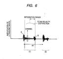
- the flow velocity distribution derived as such is then subjected to an integration process so that the flow rate can be obtained.
- an integration range is subjected to the integration process as shown in the drawing.
- the integration range is the range from the center of the tube (tube axis) to the opposite wall.
- An arbitrary length of the measurement line is divided into an arbitrary number of sections, and each section is referred to as a channel.
- each section is referred to as a channel.
- the division number is 50, it means that there are 50 channels (this division number and, hence, the number of channels determines the spatial resolution of the measurement).
- the flow velocity is thus derived per channel, and the points of the flow velocity distribution shown in FIG. 6 respectively represent the channel position and the flow velocity thereof.
- the sound velocity and the distance for the ultrasonic waves to travel in the tube wall and in the fluid are known in advance.
- calculation can be made in advance to obtain the correspondence between data timing and a channel position.
- the time taken for transmission and reception is calculated in advance for each of the channel positions on the cross section of the tube, and the thus derived correspondence between the channel position and the time can be stored.
- the flow velocity distribution is used as a basis to calculate the flow rate through an integration process. Therefore, the integration range has a large influence on the measurement precision for the flow rate.
- a quantization error generally occurs with respect to the spatial resolution, i.e., the channel positions. Due to the quantization error an integration error occurs and results in a measurement error.
- An object of the present invention is to provide a flow rate processor for a Doppler ultrasonic flow meter that is capable of obtaining the flow rate with a high precision and not influenced by a quantization error of the spatial resolution.
- the flow rate is calculated by means of an equation in which a quantization error of the spatial resolution is corrected. Accordingly, this eliminates the integration error, thereby leading to a flow rate measurement with a high precision.
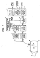
- FIG. 1 is a diagram showing the schematic structure of a Doppler ultrasonic flow meter according to a preferred embodiment of the present invention.
- the Doppler ultrasonic flow meter shown in the drawing includes an ultrasonic transducer 3, an ultrasonic wave transmission/reception section and a flow rate processor 10.
- the ultrasonic wave transmission/reception section includes a transmission/reception timing control section 4, a transmission pulse generation section 5, a transmission voltage control section 6, an amplification section 7, a filter section 8, and an A/D conversion section 9.
- the flow rate processor 10 is exemplified by a microcomputer (CPU/MPU), and includes a flow velocity distribution calculation section 11, and a flow rate calculation section 12 that are preferably implemented by the microcomputer executing a predetermined program that is stored in an internal or external storage device such as a memory, which is not shown in the drawing. Moreover, any data needed for such program execution is also stored in the storage device.
- the ultrasonic wave transmission/reception section forwards ultrasonic pulses to a measurement fluid 2 in a tube 1 with an arbitrary repetition frequency, and receives ultrasonic echoes that are reflections at a reflector or the tube inner wall.
- Doppler shift components are extracted and subjected to A/D conversion. Note here that the Doppler ultrasonic flow meter shown in the drawing is the above-described clamp-on ultrasonic flow meter.
- the above-described ultrasonic pulse is repeatedly transmitted with any predetermined pulse repetition interval.
- This pulse repetition interval is under the control of the transmission/reception timing control section 4. That is, the transmission/reception timing control section 4 follows the pulse repetition interval of its own to instruct the transmission pulse generation section 5 to generate a transmission pulse every time a pulse transmission timing comes.
- the transmission pulse generation section 5 has a quartz oscillator that generates an electric signal TXD0 of a predetermined frequency f0, and forwards the electric signal TXD0 (transmission pulse) to the transmission voltage control section 6 responding to the instruction.
- the transmission voltage control section 6 changes the voltage of the electric signal TXD0 to a predetermined voltage (transmission voltage), and forwards the resulting electric signal TXD1 to the ultrasonic transducer 3. In this manner, the ultrasonic transducer 3 transmits into the tube 1 an ultrasonic pulse of an amplitude corresponding to the transmission voltage.
- the ultrasonic transducer 3 is a transmitter/receiver for ultrasonic pulses, and the ultrasonic pulses provided from the above-described ultrasonic transducer 3 are to enter the fluid 2 flowing inside of the tube 1 with an angle ⁇ f with respect to the normal to the tube axis in the upstream direction of the fluid 2.
- These ultrasonic pulses are go-straight beams with little divergence, whose width is about 5 mm, for example.
- the ultrasonic pulses travel along a measurement line ML shown in the drawing. Note here that in FIG.
- the tube wall of the tube 1, to which the ultrasonic transducer 3 is attached is shown as a tube wall 1a (entrance wall), and the other tube wall on the opposite side is shown as a tube wall 1b (opposite wall).
- the tube's internal diameter is denoted D.
- the ultrasonic transducer 3 After receiving ultrasonic echoes as a result of the above-described ultrasonic pulses reflected by reflectors (e.g., air bubbles, foreign substances) included in the fluid 2, the ultrasonic transducer 3 converts those into electric signals, and forwards the resulting echo signals RXD0 to the amplification section 7.
- reflectors e.g., air bubbles, foreign substances
- echo signals RXD0 are low in voltage level, and by the amplification section 7, they are amplified with a predetermined amplification factor. After amplification, the resulting echo signals, i.e., amplification-controlled signals RXD1, are forwarded to the filter section 8.
- the filter section 8 subjects the signals RXD1 to separation into transmission frequency components and Doppler shift components. Thereafter, only the Doppler shift components are extracted using a low-pass filter. Thus extracted Doppler shift components are filtered signals RXD2, and they are forwarded to the A/D conversion section 9.
- the A/D conversion section 9 subjects the filtered signals RXD2 to A/D conversion based on a predetermined sampling clock, and passes the resulting A/D-converted signals RXD3 (digital data) to the flow rate processor 10.
- the sampling clock of the A/D conversion section 9 is generated and output by the transmission/reception timing control section 4, and input to the A/D conversion section 9.
- the filter section 8 is described here in detail.
- the frequency of the echoes shifts in accordance with the flow velocity (speed of the reflectors) of the fluid (Doppler shift).
- the frequency shift which is usually referred to as the Doppler frequency
- the filter section 8 signal components of the Doppler frequency (Doppler shift components) are extracted.
- the frequency of the transmitted ultrasonic pulses is combined with the frequency of the received echoes, and then the transmission frequency components are filtered.
- applied is a method of deriving analysis signals by orthogonal detection.
- multiplication is performed to sine components and cosine components of the transmission frequency so as to separate the echo waves into transmission frequency components and Doppler shift components.
- a low-pass filter is used to extract only the Doppler shift components.
- signals of thus extracted Doppler shift components are converted into digital data in the A/D conversion section 9 prior to input into the flow rate processor 10.
- the flow rate processor 10 calculates the change of phase angle in a predetermined period, and using the result, the flow velocity distribution is derived. From the flow velocity, the flow rate is derived by integration.
- the transmission frequency is on the order of hundreds of kHz to a few MHz, and the Doppler frequency is on the order of a few kHz or less.
- the flow velocity distribution calculation section 11 After the flow rate processor 10 receives the output from the A/D conversion section 9, the flow velocity distribution calculation section 11 first computes the flow velocity distribution of a measurement range along the above-described measurement line ML. Based on the calculated flow velocity distribution, specifically of a predetermined integration range thereof, the flow rate computation processing section 12 performs integration to calculate the flow rate. In the present invention, although the flow velocity distribution calculation section 11 is the same as the conventional one, the flow rate computation processing section 12 performs flow rate calculation using a flow rate calculation equation in which a quantization error of the spatial resolution is corrected.
- the integration method applies the midpoint rule (also referred to as intermediate coordinate system), and the integration range covers the range from the tube center (tube axis) to the opposite wall 1b.
- the number of channels found in such an integration range is assumed to be N+1 including channel 0 to channel N.
- the flow rate computation processing section 12 is assumed to calculate the flow rate Q using the equation (1) below, for example.
- the flow rate in a specific channel is derived by calculating, for the respective channel, the area of the tube cross section occupied by the corresponding channel, and the thus calculated area is multiplied by the flow velocity of the channel. Then, the flow rates of all channels are added together.
- the above-described equation (1) is corrected in such a manner that any region of the two channels at the starting position and the end position of the integration range that is not part of the integration range is not considered.
- the correction is described below by reference to FIG. 3.
- the channel 0 (the start channel) is described.
- the distance from the center of the tube to the center of the channel 0 is r 0 .
- the area of the channel 0 that is not part of the integration range has the length ( ⁇ r 0 /2)-r 0 , ⁇ r 0 being the width of the channel 0. How to determine which channel is the channel 0 and what is the value of r 0 will be described next.
- the distance D CH from the entrance wall 1a to a capture starting position is input.
- the capture starting position is a starting position for measurement of the flow velocity distribution, and may be arbitrarily chosen.
- the flow velocity is measured also for a channel or channels that does (do) not fall in the integration range.
- channel setting is so made that the center of a channel is at a position having the distance D CH from the entrance wall 1a, and the resulting channel is regarded as the measurement starting channel for the flow velocity distribution (CH(0) in the drawing). From the channel CH(0), channel setting is continued at ⁇ r intervals until the opposite wall 1b is reached. That is, CH(0) to CH(Z) shown in FIG.
- (Z+1) is the number of channels into which the measurement range is divided.
- the flow velocity distribution can be derived.
- the flow rate is calculated using the flow velocities only of the channels located in the integration range.
- the integration range covers the area having the length D/2 from the center of the tube to the opposite wall. Accordingly, in the FIG. 4 example, CH(M) is the starting channel of the integration range, and this is the channel 0 in FIGS. 2 and 3. Note here that the reason why M is replaced with 0 is for application to the above equation (1).
- X is the index of the channels CH(0) to CH(Z) in the measurement range, 0 ⁇ X ⁇ Z.
- the channel whose CH D (X) satisfies the following conditional equation (3) is the starting channel of the above-described integration range (CH(M) in FIG. 4, and Channel 0 in FIG. 3).
- the end channel of the integration range can also be derived from the conditional equation when D is substituted for D/2 in the conditional equation (3): D/2 - ⁇ r/2 ⁇ CH D (X) ⁇ D/2 + ⁇ r/2
- i is the index of channels in the integration range, 0 ⁇ i ⁇ N.
- the calculation is modified such that for the channel at the starting position of the integration range and that at the end position thereof, the area of that part of the respective channel that is outside of the integration range is not taken into consideration.
- the flow rate computation processing section 12 calculates the flow rate using the equation (8). Accordingly, with no influence by quantization errors of the spatial resolution, the flow rate measurement can be performed with a high precision.
- FIG. 5 shows exemplary results derived through experiments.
- the flow rate computation processing section 12 measured the flow rate using the corresponding flow rate calculation equation, i.e., corrected and not corrected, respectively.
- an electromagnetic flow meter was used as a reference meter.
- the flow rate measurement can be performed with a very high precision.
- the electromagnetic flow meter not being clamp-on type has the drawback of requiring time and effort for placement and being expensive.
Applications Claiming Priority (2)
| Application Number | Priority Date | Filing Date | Title |
|---|---|---|---|
| JP2004054264A JP2005241546A (ja) | 2004-02-27 | 2004-02-27 | ドップラー式超音波流量計、その演算処理装置、プログラム |
| JP2004054264 | 2004-02-27 |
Publications (3)
| Publication Number | Publication Date |
|---|---|
| EP1568972A2 true EP1568972A2 (fr) | 2005-08-31 |
| EP1568972A3 EP1568972A3 (fr) | 2007-09-19 |
| EP1568972B1 EP1568972B1 (fr) | 2017-10-04 |
Family
ID=34747557
Family Applications (1)
| Application Number | Title | Priority Date | Filing Date |
|---|---|---|---|
| EP05003985.8A Active EP1568972B1 (fr) | 2004-02-27 | 2005-02-24 | Processeur pour débitmètre ultrasonore à effet doppler |
Country Status (5)
| Country | Link |
|---|---|
| US (1) | US7584065B2 (fr) |
| EP (1) | EP1568972B1 (fr) |
| JP (1) | JP2005241546A (fr) |
| CN (1) | CN100449275C (fr) |
| CA (1) | CA2497607A1 (fr) |
Cited By (1)
| Publication number | Priority date | Publication date | Assignee | Title |
|---|---|---|---|---|
| EP2211150A1 (fr) * | 2007-11-15 | 2010-07-28 | National University Corporation Hokkaido University | Débitmètre multiphase à ultrasons, programme de mesure de débit multiphasique par ultrasons et procédé de mesure de débit multiphasique au moyen d'ondes ultrasonores |
Families Citing this family (28)
| Publication number | Priority date | Publication date | Assignee | Title |
|---|---|---|---|---|
| JP2008232965A (ja) * | 2007-03-23 | 2008-10-02 | Tokyo Electric Power Co Inc:The | 超音波流量計、流量測定方法およびコンピュータプログラム |
| US9026370B2 (en) | 2007-12-18 | 2015-05-05 | Hospira, Inc. | User interface improvements for medical devices |
| US8857269B2 (en) | 2010-08-05 | 2014-10-14 | Hospira, Inc. | Method of varying the flow rate of fluid from a medical pump and hybrid sensor system performing the same |
| IL208815A0 (en) | 2010-10-19 | 2011-01-31 | Raphael Valves Ind 1975 Ltd | An integrated ultrasonic flowmeter and hydraulic valve |
| AU2012299169B2 (en) | 2011-08-19 | 2017-08-24 | Icu Medical, Inc. | Systems and methods for a graphical interface including a graphical representation of medical data |
| WO2013090709A1 (fr) | 2011-12-16 | 2013-06-20 | Hospira, Inc. | Système permettant de surveiller et d'administrer un médicament à un patient et méthode l'utilisant pour réduire les risques associés à une thérapie automatisée |
| ES2741725T3 (es) | 2012-03-30 | 2020-02-12 | Icu Medical Inc | Sistema de detección de aire y método para detectar aire en una bomba de un sistema de infusión |
| US10463788B2 (en) | 2012-07-31 | 2019-11-05 | Icu Medical, Inc. | Patient care system for critical medications |
| WO2014190264A1 (fr) | 2013-05-24 | 2014-11-27 | Hospira, Inc. | Système de perfusion à multiples capteurs pour détecter la présence d'air ou d'une occlusion dans le système de perfusion |
| EP3003442B1 (fr) | 2013-05-29 | 2020-12-30 | ICU Medical, Inc. | Système de perfusion et procédé d'utilisation évitant la sursaturation d'un convertisseur analogique-numérique |
| CA2913915C (fr) | 2013-05-29 | 2022-03-29 | Hospira, Inc. | Systeme de perfusion qui emploie un ou plusieurs capteurs et des informations additionnelles pour faire une determination d'air concernant le systeme de perfusion |
| EP3110474B1 (fr) | 2014-02-28 | 2019-12-18 | ICU Medical, Inc. | Système de perfusion et procédé qui utilise la détection optique de bulles d'air à double longueur d'onde |
| JP2017517302A (ja) | 2014-05-29 | 2017-06-29 | ホスピーラ インコーポレイテッド | 構成可能閉ループ送達速度キャッチアップを有する注入システムおよびポンプ |
| CN105737916B (zh) | 2014-12-08 | 2019-06-18 | 通用电气公司 | 超声流体测量系统及方法 |
| US11344668B2 (en) | 2014-12-19 | 2022-05-31 | Icu Medical, Inc. | Infusion system with concurrent TPN/insulin infusion |
| CN104677437A (zh) * | 2015-02-12 | 2015-06-03 | 延安大学 | 一种超声波液相流量精确化测量方法 |
| US10850024B2 (en) | 2015-03-02 | 2020-12-01 | Icu Medical, Inc. | Infusion system, device, and method having advanced infusion features |
| CN105222839B (zh) * | 2015-08-21 | 2018-04-24 | 浙江天信超声技术有限公司 | 超声波流量计仪表系数的非线性修正方法 |
| WO2017197024A1 (fr) | 2016-05-13 | 2017-11-16 | Icu Medical, Inc. | Système de pompe à perfusion et procédé à purge automatique à ligne commune |
| CA3027176A1 (fr) | 2016-06-10 | 2017-12-14 | Icu Medical, Inc. | Capteur de flux acoustique pour mesures continues de debit de medicament et commande par retroaction de perfusion |
| US10089055B1 (en) | 2017-12-27 | 2018-10-02 | Icu Medical, Inc. | Synchronized display of screen content on networked devices |
| DE102018208929A1 (de) * | 2018-06-06 | 2019-12-12 | Kardion Gmbh | Verfahren zur Bestimmung einer Strömungsgeschwindigkeit eines durch ein implantiertes, vaskuläres Unterstützungssystem strömenden Fluids |
| CN111650403B (zh) * | 2019-08-02 | 2022-02-25 | 水利部交通运输部国家能源局南京水利科学研究院 | 一种多普勒流速剖面仪率定装置及其率定方法 |
| US11278671B2 (en) | 2019-12-04 | 2022-03-22 | Icu Medical, Inc. | Infusion pump with safety sequence keypad |
| CN111239850A (zh) * | 2020-03-12 | 2020-06-05 | 北京农业智能装备技术研究中心 | 一种喷头堵塞检测装置及方法 |
| WO2022020184A1 (fr) | 2020-07-21 | 2022-01-27 | Icu Medical, Inc. | Dispositifs de transfert de fluide et procédés d'utilisation |
| US11135360B1 (en) | 2020-12-07 | 2021-10-05 | Icu Medical, Inc. | Concurrent infusion with common line auto flush |
| CN113806946B (zh) * | 2021-09-22 | 2023-06-30 | 北京美科华仪科技有限公司 | 依据标准流速分布图修正垂线流速的方法 |
Citations (3)
| Publication number | Priority date | Publication date | Assignee | Title |
|---|---|---|---|---|
| JP2000097742A (ja) | 1998-09-25 | 2000-04-07 | Tokyo Electric Power Co Inc:The | ドップラ式超音波流量計 |
| JP2004061109A (ja) | 2002-06-04 | 2004-02-26 | Tokyo Electric Power Co Inc:The | ドップラ式超音波流量計、ドップラ式超音波流量計を用いた流量計測方法および流量計測用プログラム |
| EP1701139A1 (fr) | 2003-12-26 | 2006-09-13 | The Tokyo Electric Power Company Incorporated | Debitmetre ultrasonore, procede de mesure de debit, et programme d'ordinateur |
Family Cites Families (11)
| Publication number | Priority date | Publication date | Assignee | Title |
|---|---|---|---|---|
| JPS629223A (ja) | 1985-07-08 | 1987-01-17 | Kawasaki Steel Corp | 超音波による気体流量測定方法 |
| US5062427A (en) * | 1988-05-06 | 1991-11-05 | Kabushiki Kaisha Toshiba | Ultrasonic doppler apparatus |
| US5188112A (en) * | 1989-11-27 | 1993-02-23 | Acoustic Imaging Technologies Corporation | Ultrasonic Doppler imaging systems with improved flow sensitivity |
| JP3031096B2 (ja) | 1993-01-29 | 2000-04-10 | 横河電機株式会社 | 容量式電磁流量計 |
| JPH1090029A (ja) | 1996-09-13 | 1998-04-10 | Aichi Tokei Denki Co Ltd | 超音波流量計 |
| US6071242A (en) * | 1998-06-30 | 2000-06-06 | Diasonics Ultrasound, Inc. | Method and apparatus for cross-sectional color doppler volume flow measurement |
| JP2001289681A (ja) | 2000-04-07 | 2001-10-19 | Aichi Tokei Denki Co Ltd | 超音波流量計 |
| JP4169504B2 (ja) | 2001-10-26 | 2008-10-22 | 東京電力株式会社 | ドップラ式超音波流量計 |
| JP3602113B2 (ja) * | 2002-06-04 | 2004-12-15 | 東京電力株式会社 | ドップラ式超音波流量計、ドップラ式超音波流量計を用いた流量計測方法および流量計測用プログラム |
| WO2003102513A1 (fr) * | 2002-06-04 | 2003-12-11 | The Tokyo Electric Power Company, Incorporated | Debitmetre ultrasonore du type doppler, procede de mesure de debit faisant appel a un debitmetre ultrasonore du type doppler, et programme de mesure de debit utilise dans un tel debitmetre ultrasonore du type doppler |
| JP2006506190A (ja) * | 2002-11-14 | 2006-02-23 | チーム メディカル エル.エル.シー. | 診断信号処理方法及びシステム |
-
2004
- 2004-02-27 JP JP2004054264A patent/JP2005241546A/ja active Pending
-
2005
- 2005-02-05 CN CNB2005100075225A patent/CN100449275C/zh active Active
- 2005-02-18 CA CA002497607A patent/CA2497607A1/fr not_active Abandoned
- 2005-02-24 EP EP05003985.8A patent/EP1568972B1/fr active Active
- 2005-02-25 US US11/066,730 patent/US7584065B2/en active Active
Patent Citations (3)
| Publication number | Priority date | Publication date | Assignee | Title |
|---|---|---|---|---|
| JP2000097742A (ja) | 1998-09-25 | 2000-04-07 | Tokyo Electric Power Co Inc:The | ドップラ式超音波流量計 |
| JP2004061109A (ja) | 2002-06-04 | 2004-02-26 | Tokyo Electric Power Co Inc:The | ドップラ式超音波流量計、ドップラ式超音波流量計を用いた流量計測方法および流量計測用プログラム |
| EP1701139A1 (fr) | 2003-12-26 | 2006-09-13 | The Tokyo Electric Power Company Incorporated | Debitmetre ultrasonore, procede de mesure de debit, et programme d'ordinateur |
Cited By (4)
| Publication number | Priority date | Publication date | Assignee | Title |
|---|---|---|---|---|
| EP2211150A1 (fr) * | 2007-11-15 | 2010-07-28 | National University Corporation Hokkaido University | Débitmètre multiphase à ultrasons, programme de mesure de débit multiphasique par ultrasons et procédé de mesure de débit multiphasique au moyen d'ondes ultrasonores |
| US20100268486A1 (en) * | 2007-11-15 | 2010-10-21 | National University Corporation Hokkaido Unversity | Ultrasonic multiphase flowmeter, ultrasonic multiphase flow rate measurement program, and multiphase flow rate measurement method using ultrasonic wave |
| EP2211150A4 (fr) * | 2007-11-15 | 2011-12-28 | Univ Hokkaido Nat Univ Corp | Débitmètre multiphase à ultrasons, programme de mesure de débit multiphasique par ultrasons et procédé de mesure de débit multiphasique au moyen d'ondes ultrasonores |
| US8401805B2 (en) | 2007-11-15 | 2013-03-19 | National University Corporation Hokkaido University | Ultrasonic multiphase flowmeter, ultrasonic multiphase flow rate measurement program, and multiphase flow rate measurement method using ultrasonic wave |
Also Published As
| Publication number | Publication date |
|---|---|
| US20050209793A1 (en) | 2005-09-22 |
| CN100449275C (zh) | 2009-01-07 |
| JP2005241546A (ja) | 2005-09-08 |
| EP1568972B1 (fr) | 2017-10-04 |
| EP1568972A3 (fr) | 2007-09-19 |
| CA2497607A1 (fr) | 2005-08-27 |
| CN1661338A (zh) | 2005-08-31 |
| US7584065B2 (en) | 2009-09-01 |
Similar Documents
| Publication | Publication Date | Title |
|---|---|---|
| EP1568972A2 (fr) | Processeur pour débitmètre ultrasonore à effet doppler | |
| EP2116818A1 (fr) | Débitmètre ultrasonore par détermination des différences de temps de propagation | |
| JP4953001B2 (ja) | 流量計測装置、流量測定方法およびコンピュータプログラム | |
| CN100585346C (zh) | 低功率超声波流量测量 | |
| US8151653B2 (en) | Coriolis flowmeter | |
| EP3495783B1 (fr) | Transducteurs ultrasonores utilisant un saut et un codage adaptatifs multi-fréquences | |
| JP4976287B2 (ja) | パルス波形検出による超音波信号の受信点検出 | |
| US20040107779A1 (en) | Ultrasonic current meter | |
| EP2202494B1 (fr) | Compteur à ultrasons | |
| US7614310B2 (en) | Ultrasound flow sensor with a modulo-2Pi for a remaining part tracing | |
| EP1726920B1 (fr) | Procédé de mesure de débit par ultrason d'après le principe Doppler | |
| US6595070B1 (en) | Acoustic flow meters | |
| KR101764870B1 (ko) | 초음파 유량계의 신호처리시스템 | |
| RU2471153C2 (ru) | Способ и система измерения суммарного расхода текучей среды и ультразвуковой расходомер | |
| JPH11351928A (ja) | 流量計および流量計測方法 | |
| JP4278171B1 (ja) | 超音波流量計及び流量測定方法 | |
| EP3295131B1 (fr) | Procédé de détermination du temps de transit d'une salve d'ultrasons, en particulier dans un débitmètre à ultrasons, et débitmètre associé | |
| JP3438371B2 (ja) | 流量計測装置 | |
| EP1701139A1 (fr) | Debitmetre ultrasonore, procede de mesure de debit, et programme d'ordinateur | |
| JP2000180230A (ja) | 流量計及び流量測定方法 | |
| CN111337092B (zh) | 选取参考信号的方法、计算方法及相位差式超声波流量计 | |
| CN114674384A (zh) | 超声波流量计的防错波检测方法、装置、设备及流量计 | |
| JP2017215188A (ja) | 流速分布の計測方法及びその装置 | |
| JPH0682058B2 (ja) | 相関式流量計 | |
| JPS5917369B2 (ja) | 超音波流速計 |
Legal Events
| Date | Code | Title | Description |
|---|---|---|---|
| PUAI | Public reference made under article 153(3) epc to a published international application that has entered the european phase |
Free format text: ORIGINAL CODE: 0009012 |
|
| AK | Designated contracting states |
Kind code of ref document: A2 Designated state(s): AT BE BG CH CY CZ DE DK EE ES FI FR GB GR HU IE IS IT LI LT LU MC NL PL PT RO SE SI SK TR |
|
| AX | Request for extension of the european patent |
Extension state: AL BA HR LV MK YU |
|
| PUAL | Search report despatched |
Free format text: ORIGINAL CODE: 0009013 |
|
| AK | Designated contracting states |
Kind code of ref document: A3 Designated state(s): AT BE BG CH CY CZ DE DK EE ES FI FR GB GR HU IE IS IT LI LT LU MC NL PL PT RO SE SI SK TR |
|
| AX | Request for extension of the european patent |
Extension state: AL BA HR LV MK YU |
|
| 17P | Request for examination filed |
Effective date: 20080318 |
|
| AKX | Designation fees paid |
Designated state(s): CH DE FR GB IT LI |
|
| RAP1 | Party data changed (applicant data changed or rights of an application transferred) |
Owner name: FUJI ELECTRIC CO., LTD. |
|
| 17Q | First examination report despatched |
Effective date: 20120518 |
|
| GRAP | Despatch of communication of intention to grant a patent |
Free format text: ORIGINAL CODE: EPIDOSNIGR1 |
|
| INTG | Intention to grant announced |
Effective date: 20170621 |
|
| RIN1 | Information on inventor provided before grant (corrected) |
Inventor name: HIRAYAMA, NORITOMO Inventor name: YAMADA, KAZUYUKI Inventor name: OHMURO, YOSHINORI Inventor name: KISHIRO, MASAMI |
|
| GRAS | Grant fee paid |
Free format text: ORIGINAL CODE: EPIDOSNIGR3 |
|
| GRAA | (expected) grant |
Free format text: ORIGINAL CODE: 0009210 |
|
| RIN1 | Information on inventor provided before grant (corrected) |
Inventor name: KISHIRO, MASAMI Inventor name: HIRAYAMA, NORITOMO Inventor name: YAMADA, KAZUYUKI Inventor name: OHMURO, YOSHINORI |
|
| RAP1 | Party data changed (applicant data changed or rights of an application transferred) |
Owner name: FUJI ELECTRIC CO., LTD. |
|
| AK | Designated contracting states |
Kind code of ref document: B1 Designated state(s): CH DE FR GB IT LI |
|
| REG | Reference to a national code |
Ref country code: GB Ref legal event code: FG4D |
|
| REG | Reference to a national code |
Ref country code: CH Ref legal event code: EP |
|
| REG | Reference to a national code |
Ref country code: DE Ref legal event code: R096 Ref document number: 602005052828 Country of ref document: DE |
|
| REG | Reference to a national code |
Ref country code: FR Ref legal event code: PLFP Year of fee payment: 14 |
|
| REG | Reference to a national code |
Ref country code: DE Ref legal event code: R097 Ref document number: 602005052828 Country of ref document: DE |
|
| PLBE | No opposition filed within time limit |
Free format text: ORIGINAL CODE: 0009261 |
|
| STAA | Information on the status of an ep patent application or granted ep patent |
Free format text: STATUS: NO OPPOSITION FILED WITHIN TIME LIMIT |
|
| PG25 | Lapsed in a contracting state [announced via postgrant information from national office to epo] |
Ref country code: IT Free format text: LAPSE BECAUSE OF FAILURE TO SUBMIT A TRANSLATION OF THE DESCRIPTION OR TO PAY THE FEE WITHIN THE PRESCRIBED TIME-LIMIT Effective date: 20171004 |
|
| 26N | No opposition filed |
Effective date: 20180705 |
|
| PGFP | Annual fee paid to national office [announced via postgrant information from national office to epo] |
Ref country code: FR Payment date: 20220118 Year of fee payment: 18 |
|
| PGFP | Annual fee paid to national office [announced via postgrant information from national office to epo] |
Ref country code: CH Payment date: 20230307 Year of fee payment: 19 |
|
| PGFP | Annual fee paid to national office [announced via postgrant information from national office to epo] |
Ref country code: GB Payment date: 20230105 Year of fee payment: 19 Ref country code: DE Payment date: 20221229 Year of fee payment: 19 |