EP1568926A1 - Fluid control device - Google Patents
Fluid control device Download PDFInfo
- Publication number
- EP1568926A1 EP1568926A1 EP03770066A EP03770066A EP1568926A1 EP 1568926 A1 EP1568926 A1 EP 1568926A1 EP 03770066 A EP03770066 A EP 03770066A EP 03770066 A EP03770066 A EP 03770066A EP 1568926 A1 EP1568926 A1 EP 1568926A1
- Authority
- EP
- European Patent Office
- Prior art keywords
- channel
- lines
- block
- blocks
- line interconnecting
- Prior art date
- Legal status (The legal status is an assumption and is not a legal conclusion. Google has not performed a legal analysis and makes no representation as to the accuracy of the status listed.)
- Withdrawn
Links
Images






Classifications
-
- F—MECHANICAL ENGINEERING; LIGHTING; HEATING; WEAPONS; BLASTING
- F16—ENGINEERING ELEMENTS AND UNITS; GENERAL MEASURES FOR PRODUCING AND MAINTAINING EFFECTIVE FUNCTIONING OF MACHINES OR INSTALLATIONS; THERMAL INSULATION IN GENERAL
- F16K—VALVES; TAPS; COCKS; ACTUATING-FLOATS; DEVICES FOR VENTING OR AERATING
- F16K27/00—Construction of housing; Use of materials therefor
- F16K27/003—Housing formed from a plurality of the same valve elements
-
- F—MECHANICAL ENGINEERING; LIGHTING; HEATING; WEAPONS; BLASTING
- F16—ENGINEERING ELEMENTS AND UNITS; GENERAL MEASURES FOR PRODUCING AND MAINTAINING EFFECTIVE FUNCTIONING OF MACHINES OR INSTALLATIONS; THERMAL INSULATION IN GENERAL
- F16K—VALVES; TAPS; COCKS; ACTUATING-FLOATS; DEVICES FOR VENTING OR AERATING
- F16K13/00—Other constructional types of cut-off apparatus; Arrangements for cutting-off
-
- F—MECHANICAL ENGINEERING; LIGHTING; HEATING; WEAPONS; BLASTING
- F16—ENGINEERING ELEMENTS AND UNITS; GENERAL MEASURES FOR PRODUCING AND MAINTAINING EFFECTIVE FUNCTIONING OF MACHINES OR INSTALLATIONS; THERMAL INSULATION IN GENERAL
- F16K—VALVES; TAPS; COCKS; ACTUATING-FLOATS; DEVICES FOR VENTING OR AERATING
- F16K25/00—Details relating to contact between valve members and seats
-
- F—MECHANICAL ENGINEERING; LIGHTING; HEATING; WEAPONS; BLASTING
- F16—ENGINEERING ELEMENTS AND UNITS; GENERAL MEASURES FOR PRODUCING AND MAINTAINING EFFECTIVE FUNCTIONING OF MACHINES OR INSTALLATIONS; THERMAL INSULATION IN GENERAL
- F16K—VALVES; TAPS; COCKS; ACTUATING-FLOATS; DEVICES FOR VENTING OR AERATING
- F16K51/00—Other details not peculiar to particular types of valves or cut-off apparatus
-
- Y—GENERAL TAGGING OF NEW TECHNOLOGICAL DEVELOPMENTS; GENERAL TAGGING OF CROSS-SECTIONAL TECHNOLOGIES SPANNING OVER SEVERAL SECTIONS OF THE IPC; TECHNICAL SUBJECTS COVERED BY FORMER USPC CROSS-REFERENCE ART COLLECTIONS [XRACs] AND DIGESTS
- Y10—TECHNICAL SUBJECTS COVERED BY FORMER USPC
- Y10T—TECHNICAL SUBJECTS COVERED BY FORMER US CLASSIFICATION
- Y10T137/00—Fluid handling
- Y10T137/8593—Systems
- Y10T137/877—With flow control means for branched passages
- Y10T137/87885—Sectional block structure
Definitions
- the present invention relates to fluid control devices for use in semiconductor manufacturing apparatus, and more particularly to integrated fluid control devices which are so assembled that fluid controllers are individually removable upward for maintenance and inspection.
- front With respect to the terms "front,” “rear,” “upper” and “lower” as used herein, the right-hand side of FIG. 1 will be referred to as “front,” the left-hand side thereof as “rear,” the upper and lower sides of the same drawing as “upper” and “lower,” and the terms “left” and “right” are used for the device as it is seen from behind toward the front.
- front the front-to-rear direction reversed or with their upper and lower sides positioned as the left and right sides.
- Fluid control devices for use in semiconductor manufacturing apparatus comprise various fluid controllers arranged in rows.
- the channels of fluid controllers in adjacent rows are interconnected by connecting means at specified locations.
- massflow controllers and shut-off valves are connected and integrated into a device without using tubes in recent years.
- JP-A No. 2002-89798 discloses a fluid control device comprising a plurality of lines arranged in parallel on a base plate and having respective inlets, as well as respective outlets, facing toward the same direction, each of the lines comprising a plurality of fluid controllers arranged in an upper stage and a plurality of coupling members arranged in a lower stage, the specified lines among these lines having fluid channels thereof interconnected by line interconnecting means.
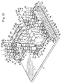
- FIG. 13 is a perspective view showing an example of fluid control device disclosed in the publication of JP-A No. 2002-89798.
- the device comprises, as arranged in parallel on a base plate 1, three bypassless lines A1, A2, A3, and three lines B1, B2, B3 having bypass channels.
- the bypassless lines A1, A2, A3, and the bypass-having lines B1, B2, B3 comprise a massflow controller, shut-off valve, shutoff-opening device and like fluid controllers 2, 3, 4, 5, 6, 7 arranged in an upper stage, and coupling members 11, 12, 13, 14, 15, 16, 17, 40 arranged in a lower stage for interconnecting the fluid controllers 2, 3, 4, 5, 6, 7, 41.
- the fluid controllers of each of the bypassless lines A1 to A3 are a massflow controller 2, an inlet-side shut-off valve 3 disposed at the inlet side of the massflow controller 2 with a filter 4 interposed therebetween and an outlet-side shut-off valve 5 provided at the outlet side of the massflow controller 2.
- the fluid controllers of each of the bypass-having lines B1 to B3 are a massflow controller 2, an inlet-side shutoff-opening device 6 disposed at the inlet side of the massflow controller 2 with a filter 4 interposed therebetween and an outlet-side shutoff-opening device 7 disposed at the outlet side of the massflow controller 2.
- the inlet-side shutoff-opening device 6 comprises a blocklike body 21, two shut-off valve actuators 22, 23 mounted on the body 21, a blocklike coupling 24 having a tubular connector and mounted on the upper side of the body 21 and a channel block 25 attached to a side portion of the body 21.
- the outlet-side shutoff-opening device 7 comprises a first blocklike body (not shown) disposed close to a massflow controller 2, a first shut-off valve actuator 27 mounted on the body, a second blocklike body 28 disposed on the rear side of the first blocklike body 26 adjacent thereto, two shut-off valve actuators 29, 30 mounted on the body 28, a blocklike coupling 31 having a tubular connector and mounted on the upper side of the first body 26, a channel block 32 attached to the front side of the same and a blocklike coupling 33 having a tubular connector and mounted on the upper side of the second body 28.
- a T-shaped tubular coupling (not shown) for branching off a bypass channel is disposed between a blocklike coupling 14 under the filter 4 and a tubular coupling 15 for connecting the massflow controller.
- An inverted U-shaped bypass pipe 35 extending above the massflow controller 2 has one end joined to this T-shaped coupling 34 and the other end joined to a blockline coupling (not shown) having a tubular connector and provided for the outlet-side shutoff-opening device 7.
- a tubular coupling 36 for dividing the pipe 35 into an inverted L-shaped portion and an I-shaped portion.
- the massflow controller 2 and the couplings 11, 12, 14 are fixed to the base plate 1 with inverted U-shaped brackets 8, 9, 19.
- the massflow controller 2 is singly removable upward by removing the couplings 15, 17 from opposite sides thereof, and the filter 4 and the shut-off valves 3, 5 are individually similarly removable by removing screws 37 which are driven in from above.
- Indicated at 40 is a single manifold block coupling for interconnecting the three bypassless lines A1 to A3.
- Indicated at 43 is a single manifold block coupling for interconnecting the three bypass-having lines B1 to B3.
- Indicated at 41 are channel closing blocks fastened to the manifold block coupling 40 with screws 37.
- Indicated at 42 is an inverted U-shaped bracket for attaching the manifold couplings 40, 43 to the base plate 1.
- the manifold block coupling 40 for the bypassless lines is connected to the manifold block coupling 43 for the bypass-having lines by a communication pipe 44, and a common outlet for these lines is provided at the terminal end of the manifold block coupling 43 for the bypass-having lines.
- a shut-off valve 45 having a tubular coupling 46 is provided at this location.
- the blocklike couplings 24 each having a tubular connector and included in the inlet-side shutoff-opening device 6 are interconnected by an inverted U-shaped communication pipe 47 serving as line interconnecting means
- the second blocklike couplings 33 each having a tubular connector and included in the outlet-side shutoff-opening device 7 are interconnected by an inverted U-shaped communication pipe 48 serving as line interconnecting means.
- These line interconnecting means comprise L-shaped couplings L and T-shaped couplings T, and these couplings L, T and pipe members P are joined by welding (indicated at W in the drawing).
- each line has blocklike couplings arranged in the lower stage and removably fastened to the base plate, and fluid controllers arranged in the upper stage and removably mounted on the couplings in the lower stage, whereby each controller of each line is made easy to remove and mount in place.
- the line interconnecting means comprises couplings which are interconnected by pipe members and welding, the device has the problem that the addition and modification of lines require much time and labor for disconnecting and interconnecting the lines.
- An object of the present invention is to provide an integrated fluid control device wherein the means for interconnecting the channels of lines has no welded portions so that lines can be added or modified with great ease.
- the present provides a fluid control device comprising a plurality of lines arranged in parallel and having respective inlets, as well as respective outlets, facing toward the same direction, each of the lines comprising a plurality of fluid controllers arranged in an upper stage and a plurality of coupling members arranged in a lower stage, specified lines among said lines having fluid channels thereof interconnected by line interconnecting means, the fluid control device being characterized in that the line interconnecting means comprises lower channel blocks each having a line interconnecting channel and arranged in upper stage of the specified lines interconnected, at the same position with respect to the direction of the lines, the line interconnecting channel having at least one upward opening, and at least one upper channel block disposed on an upper side of the lower channel blocks of adjacent lines interconnected and having a transverse channel extending orthogonal to the lines and downward channels extending from the transverse channel and communicating with the upward openings of the respective line interconnecting channels of the lower channel blocks, each of the lower channel blocks being removably fastened to the coupling member in the lower stage with screws from
- the coupling members for placing fluid controllers thereon are each in the form of a rectangular parallelepipedal block, and the fluid controller has a lower portion (the portion to be placed on the coupling member) which is also a rectangular parallelepipedal block.
- the lower channel block and the upper channel block are also rectangular parallelepipedal.
- the lower channel block has in the direction of the line thereof a width equal to the width of the fluid controller and the coupling member constituting the line, and is disposed in the upper stage which is at the same level as the fluid controller.
- the upper channel block has in a direction orthogonal to the line a length approximately equal to the width of the line.
- the number of upper channel blocks to be provided is smaller than the number of lines to be interconnected by one, and each upper channel block is mounted on the lower channel blocks of adjacent two lines to be interconnected.
- the upper channel block may have a length orthogonal to the line and extending over all lines to be interconnected, and only one block may be mounted across all the lines.
- Intermediate blocks for adjusting the height of the upper channel blocks may be interposed between the upper channel block and the lower channel blocks.
- an intermediate block may be disposed at a position adjacent to the lower channel block with respect to the direction of the line for adjusting the position of the upper channel block. The latter intermediate block can be replaced by a check valve.
- the line interconnecting means comprises a lower and an upper channel block, and the lower channel block and the upper channel block are removable, so that the line interconnecting means can be provided without welding.
- blocks are removed as required from among the channel blocks constituting the line interconnecting means, and the lines to be added are thereafter installed on the base plate.
- the channel blocks used before the addition and the channel blocks prepared anew are used for providing the line interconnecting means according to the altered specifications, and this prepared means is installed in place.
- the lines can be modified similarly. Thus, lines can be added and modified easily.
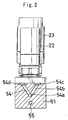
- FIGS. 1 to 5 show the main portions of a first embodiment of fluid control device according to the present invention.
- FIG. 1 shows inlet-side shutoff-opening devices 6 each comprising a blocklike body 21 and two shut-off valve actuators 22, 23 mounted on the body 21.
- a lower channel block 51 for interconnecting lines is disposed on the rear side of the body 21 of the shutoff-opening device 6.
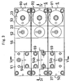
- An intermediate block 56 shown in FIGS. 3 and 4 and serving, for example, as a check valve (not shown in detail) can be removably provided between the body 21 of the shutoff-opening device 6 and the lower channel block 51.
- the front shut-off valve actuator 23 of the on-off valve 6 is a 3-port valve
- the rear shut-off valve actuator 22 is a 2-port valve.
- the device body 21 comprises two blocks 52, 53 for the 2-port valve and the 3-port valve, respectively.
- Formed in the block 53 for the 3-port valve are an inlet channel 53a extending from a front port and having a downward opening, a first outlet channel 53b extending from a rear port and having a rearward opening, and a second outlet channel 53c extending from a center port and having a rearward opening.
- an inlet channel 52a for causing the first outlet channel 53b of the block 53 to communicate with the front port of the 2-port valve therethrough, a bypass channel 52b communicating with the second outlet channel 53c of the block 53 and extending through the block 52 from the front rearward, and an outlet channel 52c extending from a rear port of the block 52 and having a rearward opening.
- the lower channel block 51 for line interconnection has a line interconnecting channel 54 communicating with the outlet channel 52c of the 2-port valve block 52 of the inlet-side shutoff-opening device 6 and having an upward opening, and an in-line connecting channel 55 communicating with the bypass channel 52b of the block 52 of the device 6 and having a downward opening.
- the line interconnecting channel 54 comprises a line-direction channel 54a extending rearward from the opening of the outlet channel 52c of the device 6, and an upward channel 54b extending upward from the rear end of the channel 54a and having an upward opening. As shown in FIG.
- the upward channel 54b comprises two branch channels arranged in a V shape and extending obliquely upwardly leftward and rightward, respectively, when seen from behind and has right and left upward openings 54c, 54d spaced apart by a predetermined distance orthogonal to the line.
- Preferred embodiment of line interconnecting means 50 to be used in the place of the line interconnecting means 47, 48 shown in FIG. 13 comprises a plurality of (i.e., three shown) lower channel blocks 51, and a plurality of (i.e., two in the illustration) upper channel blocks 57 arranged on the upper side of the lower channel blocks 51 as shown in FIGS. 3 to 5.
- the lower channel blocks 51 are arranged in the upper stage of the lines B1, B2, B3 to be interconnected at the same position with respect to the direction of the lines (front-rear direction).
- Each upper channel block 57 comprises two blocks 57a, 57b joined to each other and is internally provided with an inverted U-shaped channel 58 which is open downward.
- the inverted U-shaped channel 58 comprises a transverse channel 58a extending orthogonal to the lines and two parallel downward channels 58b extending downward respectively from the left and right ends of the transverse channel 58a.
- the upper channel block 57 is positioned on adjacent two lower channel blocks 51, and the inverted U-shaped channel 58 causes the left upward opening 54d of the lower channel block 51 of the right line B1 or B2 to communicate with the right upward opening 54c of the lower channel block 51 of the left line.
- the lower channel block 51 is removably fastened to a coupling member (blocklike coupling member indicated, for example, at 11 or 12 in FIG. 13) with screws 37 from above.
- the upper channel block 57 is removably fastened to the adjacent two lower channel blocks 51 with screws 59 from above.
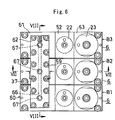
- FIGS. 6 to 8 show main portions of a second embodiment of fluid control device according to the invention.
- the second embodiment differs from the first embodiment with respect to the constructions of lower channel blocks 61 and an upper channel block 62 of line interconnecting means 60.
- like parts are designated by like reference numerals and will not be described repeatedly.
- the means 60 for interconnecting the channels of specified lines B1, B2, B3 comprises a plurality of (i.e., three shown) lower channel blocks 61, and one upper channel block 62 disposed on the upper side of the lower channel blocks 61.
- the lower channel block 61 is internally provided with a line interconnecting channel 64 communicating with an outlet channel 52c of 2-port valve block 52 of an inlet-side shutoff-opening device 6 and having an upward opening, and an in-line connecting channel 65 communicating with a bypass channel 52b of the block 52 of the device 6.
- the line interconnecting channel 64 comprises a line-direction channel 64a extending rearward from the opening of the outlet channel 52c of the shutoff-opening device 6, and an upward channel 64b extending upward from the rear end of the line-direction channel 64a and having an upward opening 64c.
- the upward channel 64b is I-shaped and extends upward.
- the upper channel block 62 which is singly provided, has inside thereof a transverse channel 66 extending in the left-right direction, and downward channels 67 extending downward from the transverse channel 66 and communicating with the openings of upward channels 64b of line interconnecting channels 64 of the respective lower channel blocks 61.
- the upper channel block 62 is provided on and extends across all the lower channel blocks 61 of the three lines B1, B2, B4 and has its downward channels 67 aligned with the respective upward channels 64b of the lower channel blocks 61.
- the transverse channel 66 is closed at its left and right ends; a left-end opening formed in making the channel is closed with a closure member 68.
- Each lower channel block 61 is removably fastened to a coupling member (blocklike coupling member indicated, for example, at 11 or 12 in FIG. 13) with screws 37 from above.
- the upper channel block 62 is removably fastened to the lower channel blocks 61 with screws 59 from above.
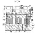
- FIGS. 9 to 11 show main portions of a third embodiment of fluid control device according to the invention.
- the third embodiment differs from the second embodiment in that another block 71 is provided between each lower channel block 61 of the line interconnecting means and the upper channel block 62 thereof.
- like parts are designated by like reference numerals and will not be described repeatedly.
- line interconnecting means 70 for interconnecting the channels of the specified lines B1, B2, B3 comprises a plurality of lower channel blocks 61, one upper channel block 62 disposed above the lower channel blocks 61 and a plurality of intermediate channel blocks 71 (the same as the lower blocks 61 in number) interposed between the blocks 61, 62.
- the intermediate channel block 71 has an I-shaped channel 72 having an upward and a downward opening for causing the upward channel 64b of the corresponding lower channel block 61 to communicate with the corresponding downward channel 67 of the upper channel block 62.
- These upward channel 64b, the I-shaped channel 72 and the downward channel 67 are vertically arranged in alignment so as to ensure reduced flow resistance.
- the upper channel block 62 is positioned at a level higher than in the second embodiment by an amount corresponding to the height of the intermediate channel block 71, whereby the upper block 72 is positioned approximately at the same level as the shut-off valve actuators 22, 23. This renders the upper block 62 easier to remove from and mount on the lower block 61.
- FIG. 12 shows a fourth embodiment of fluid control device according to the invention.
- the fourth embodiment differs from the second embodiment in that the line interconnecting means 80 has other blocks 81 adjacent to the lower channel blocks 61.
- like parts are designated by like reference numerals, and will not be described repeatedly.
- the means 80 of this embodiment for interconnecting the channels of the specified lines B1, B2, B3 comprises a plurality of lower channel blocks 61, one upper channel block 62 disposed on the upper side of the lower channel block 61, and a plurality of intermediate channel blocks 81 (the same as the lower channel block 61 in number) interposed between the lower channel blocks 61 and the shutoff-opening devices 6.
- Each intermediate channel block 81 has parallel upper and lower straight channels 82, 83 each having a forward and a rearward opening.
- the upper straight channel 82 holds the outlet channel 52c of the shutoff-opening device 6 in communication with the line-direction channel 64a of the lower channel block 61.
- the lower straight channel 83 causes the bypass channel 52b of the shutoff-opening device 6 to communicate with the in-line connecting channel 65 of the lower channel block 61. While the communication portion between the lower block 61 and the shutoff-opening device 6 remains in the same direction as in the second embodiment, this increases the distance between the upper channel block 62 and the shutoff-opening device 6. This shifts the position of the upper channel block 62 rearward as desired, further rendering the upper block 62 easier to remove from or mount on the lower block 61.
Landscapes
- Engineering & Computer Science (AREA)
- General Engineering & Computer Science (AREA)
- Mechanical Engineering (AREA)
- Valve Housings (AREA)
- Pipeline Systems (AREA)
Abstract
Description
Claims (1)
- A fluid control device comprising a plurality of lines arranged in parallel and having respective inlets, as well as respective outlets, facing toward the same direction, each of the lines comprising a plurality of fluid controllers arranged in an upper stage and a plurality of coupling members arranged in a lower stage, specified lines among said lines having fluid channels thereof interconnected by line interconnecting means,
the fluid control device being characterized in that the line interconnecting means comprises lower channel blocks each having a line interconnecting channel and arranged in upper stage of the specified lines interconnected, at the same position with respect to the direction of the lines, the line interconnecting channel having at least one upward opening, and at least one upper channel block disposed on an upper side of the lower channel blocks of adjacent lines interconnected and having a transverse channel extending orthogonal to the lines and downward channels extending from the transverse channel and communicating with the upward openings of the respective line interconnecting channels of the lower channel blocks, each of the lower channel blocks being removably fastened to the coupling member in the lower stage with screws from above, the upper channel block being removably fastened to the lower channel blocks with screws from above.
Applications Claiming Priority (3)
| Application Number | Priority Date | Filing Date | Title |
|---|---|---|---|
| JP2002351025A JP2004183771A (en) | 2002-12-03 | 2002-12-03 | Fluid control device |
| JP2002351025 | 2002-12-03 | ||
| PCT/JP2003/013976 WO2004051124A1 (en) | 2002-12-03 | 2003-10-31 | Fluid control device |
Publications (2)
| Publication Number | Publication Date |
|---|---|
| EP1568926A1 true EP1568926A1 (en) | 2005-08-31 |
| EP1568926A4 EP1568926A4 (en) | 2007-03-28 |
Family
ID=32463129
Family Applications (1)
| Application Number | Title | Priority Date | Filing Date |
|---|---|---|---|
| EP03770066A Withdrawn EP1568926A4 (en) | 2002-12-03 | 2003-10-31 | Fluid control device |
Country Status (7)
| Country | Link |
|---|---|
| US (1) | US7152629B2 (en) |
| EP (1) | EP1568926A4 (en) |
| JP (1) | JP2004183771A (en) |
| KR (1) | KR101001238B1 (en) |
| CN (1) | CN100439779C (en) |
| TW (1) | TWI313888B (en) |
| WO (1) | WO2004051124A1 (en) |
Families Citing this family (34)
| Publication number | Priority date | Publication date | Assignee | Title |
|---|---|---|---|---|
| JPWO2007017937A1 (en) * | 2005-08-10 | 2009-02-19 | 株式会社フジキン | Fluid control device |
| US7575616B2 (en) | 2006-02-10 | 2009-08-18 | Entegris, Inc. | Low-profile surface mount filter |
| JP5096696B2 (en) * | 2006-03-02 | 2012-12-12 | サーパス工業株式会社 | Fluid equipment unit structure |
| US8196480B1 (en) * | 2006-04-03 | 2012-06-12 | A+ Manufacturing, Llc | Modular sample conditioning system |
| US8104516B2 (en) * | 2006-06-02 | 2012-01-31 | Ckd Corporation | Gas supply unit and gas supply system |
| JP2007327542A (en) * | 2006-06-07 | 2007-12-20 | Surpass Kogyo Kk | Fluid apparatus unit structure |
| US20110041470A1 (en) * | 2006-08-25 | 2011-02-24 | Pall Corporation | Fluid assemblies comprising a purification element |
| US7806143B2 (en) * | 2007-06-11 | 2010-10-05 | Lam Research Corporation | Flexible manifold for integrated gas system gas panels |
| US20090114295A1 (en) * | 2007-11-06 | 2009-05-07 | Ultra Clean Holdings, Inc. | Gas-panel assembly |
| JP4944049B2 (en) * | 2008-01-31 | 2012-05-30 | シーケーディ株式会社 | Chemical supply device |
| US20100282993A1 (en) * | 2009-05-11 | 2010-11-11 | Timothy Robert Kerrigan | Continuous Flow Bypass Manifold |
| WO2011101934A1 (en) * | 2010-02-22 | 2011-08-25 | 株式会社フジキン | Mixture gas supply device |
| US10107407B2 (en) * | 2010-09-28 | 2018-10-23 | Parker-Hannifin Corporation | Modular valve manifold system |
| JP5785813B2 (en) * | 2011-08-10 | 2015-09-30 | 株式会社フジキン | Fluid control device |
| US9188990B2 (en) | 2011-10-05 | 2015-11-17 | Horiba Stec, Co., Ltd. | Fluid mechanism, support member constituting fluid mechanism and fluid control system |
| JP5868219B2 (en) * | 2012-02-29 | 2016-02-24 | 株式会社フジキン | Fluid control device |
| JP6012247B2 (en) * | 2012-04-27 | 2016-10-25 | 株式会社フジキン | Fluid control device |
| JP6147113B2 (en) * | 2013-06-27 | 2017-06-14 | 株式会社フジキン | Fitting for fluid control device and fluid control device |
| JP6175300B2 (en) * | 2013-07-17 | 2017-08-02 | 株式会社フジキン | Fitting member for fluid control device and fluid control device |
| CN105659177B (en) * | 2013-10-31 | 2018-07-10 | 株式会社富士金 | Pressure flow-rate controller |
| JP6186275B2 (en) * | 2013-12-27 | 2017-08-23 | 株式会社フジキン | Fluid control device |
| KR20160120336A (en) * | 2014-07-29 | 2016-10-17 | 토쿠시마 대학 | Inline concentration measurement device |
| JP1528532S (en) * | 2014-09-30 | 2015-07-13 | ||
| US9639094B2 (en) * | 2014-11-12 | 2017-05-02 | Michael D. Palmer | Electronic pneumatic pressure controller |
| WO2016114266A1 (en) * | 2015-01-16 | 2016-07-21 | 株式会社キッツエスシーティー | Block valve and block valve for raw material container |
| JP1539278S (en) * | 2015-03-31 | 2015-11-30 | ||
| US11357966B2 (en) | 2015-04-23 | 2022-06-14 | B. Braun Medical Inc. | Compounding device, system, kit, software, and method |
| KR102149689B1 (en) * | 2016-06-21 | 2020-08-31 | 가부시키가이샤 후지킨 | Fluid control device |
| JP2018084255A (en) * | 2016-11-21 | 2018-05-31 | 東京エレクトロン株式会社 | Fluid control device |
| JP7030342B2 (en) * | 2017-03-28 | 2022-03-07 | 株式会社フジキン | Joint block and fluid control device using it |
| WO2019044541A1 (en) * | 2017-08-31 | 2019-03-07 | 株式会社フジキン | Joint block and manufacturing method for same |
| KR102295310B1 (en) * | 2017-10-31 | 2021-08-30 | 가부시키가이샤 후지킨 | valve device |
| JP7372664B2 (en) * | 2019-09-30 | 2023-11-01 | 株式会社フジキン | Fitting block assembly and fluid control device |
| FR3116000B1 (en) * | 2020-11-10 | 2023-06-02 | Novasep Process | Assembly of fluidic modules |
Family Cites Families (19)
| Publication number | Priority date | Publication date | Assignee | Title |
|---|---|---|---|---|
| KR100232112B1 (en) * | 1996-01-05 | 1999-12-01 | 아마노 시게루 | Gas supply unit |
| JP3997337B2 (en) * | 1996-11-20 | 2007-10-24 | 忠弘 大見 | Fluid control device |
| JP3997338B2 (en) * | 1997-02-14 | 2007-10-24 | 忠弘 大見 | Fluid control device |
| US6152175A (en) * | 1997-06-06 | 2000-11-28 | Ckd Corporation | Process gas supply unit |
| US6068016A (en) * | 1997-09-25 | 2000-05-30 | Applied Materials, Inc | Modular fluid flow system with integrated pump-purge |
| JP4378553B2 (en) * | 1997-10-13 | 2009-12-09 | 忠弘 大見 | Fluid control device |
| JP4110304B2 (en) * | 1998-06-30 | 2008-07-02 | 株式会社フジキン | Fluid control device and fluid control device assembly method |
| JP3921565B2 (en) * | 1998-07-10 | 2007-05-30 | 株式会社フジキン | Fluid control device |
| JP2000145979A (en) * | 1998-11-16 | 2000-05-26 | Fujikin Inc | Lower stage member fixing device and fluid controller equipped with the same |
| US6298881B1 (en) | 1999-03-16 | 2001-10-09 | Shigemoto & Annett Ii, Inc. | Modular fluid handling assembly and modular fluid handling units with double containment |
| AU6620600A (en) * | 1999-09-01 | 2001-03-26 | Silicon Valley Group, Inc. | Layered block fluid delivery system |
| JP4238453B2 (en) * | 2000-03-10 | 2009-03-18 | 株式会社東芝 | Fluid control device |
| EP1132669B1 (en) * | 2000-03-10 | 2004-10-13 | Tokyo Electron Limited | Fluid control apparatus |
| JP3482601B2 (en) * | 2000-06-30 | 2003-12-22 | 東京エレクトロン株式会社 | Fluid control device |
| JP2002089798A (en) * | 2000-09-11 | 2002-03-27 | Ulvac Japan Ltd | Fluid control device and gas treatment equipment using it |
| JP2002349797A (en) * | 2001-05-23 | 2002-12-04 | Fujikin Inc | Fluid control device |
| US6953048B2 (en) * | 2001-09-07 | 2005-10-11 | Circle Seal Controls, Inc. | Modular surface-mount fluid-flow system |
| US6874538B2 (en) * | 2003-03-26 | 2005-04-05 | Kevin S. Bennett | Fluid delivery system |
| US7004199B1 (en) * | 2004-08-04 | 2006-02-28 | Fujikin Incorporated | Fluid control apparatus |
-
2002
- 2002-12-03 JP JP2002351025A patent/JP2004183771A/en active Pending
-
2003
- 2003-10-31 EP EP03770066A patent/EP1568926A4/en not_active Withdrawn
- 2003-10-31 WO PCT/JP2003/013976 patent/WO2004051124A1/en not_active Ceased
- 2003-10-31 CN CNB2003801012294A patent/CN100439779C/en not_active Expired - Fee Related
- 2003-10-31 KR KR1020057009992A patent/KR101001238B1/en not_active Expired - Lifetime
- 2003-10-31 US US10/537,093 patent/US7152629B2/en not_active Expired - Lifetime
- 2003-12-01 TW TW92133631A patent/TWI313888B/en not_active IP Right Cessation
Also Published As
| Publication number | Publication date |
|---|---|
| JP2004183771A (en) | 2004-07-02 |
| US20060048830A1 (en) | 2006-03-09 |
| CN100439779C (en) | 2008-12-03 |
| US7152629B2 (en) | 2006-12-26 |
| WO2004051124A1 (en) | 2004-06-17 |
| KR20050089154A (en) | 2005-09-07 |
| TW200416796A (en) | 2004-09-01 |
| KR101001238B1 (en) | 2010-12-17 |
| TWI313888B (en) | 2009-08-21 |
| CN1703596A (en) | 2005-11-30 |
| EP1568926A4 (en) | 2007-03-28 |
Similar Documents
| Publication | Publication Date | Title |
|---|---|---|
| US7152629B2 (en) | Fluid control device | |
| EP0859155B1 (en) | Fluid control apparatus | |
| EP1132669B1 (en) | Fluid control apparatus | |
| JP3546275B2 (en) | Fluid control device | |
| EP1191265B1 (en) | Fluid control apparatus and gas treatment system comprising same | |
| US6035893A (en) | Shutoff-opening devices and fluid control apparatus comprising such devices | |
| EP0908930B1 (en) | Fluid control apparatus | |
| JP2002349797A (en) | Fluid control device | |
| US7004199B1 (en) | Fluid control apparatus | |
| EP1498666A1 (en) | Fluid controller | |
| JP7061808B2 (en) | Fittings and fluid controls | |
| EP1568927B1 (en) | Fluid control device | |
| EP1895214A1 (en) | Fluid control device | |
| KR100633747B1 (en) | Coupling member for use in fluid control apparutus and method of fabricating same | |
| CN110494686A (en) | Fitting block and fluid control device using the same | |
| JP4395641B2 (en) | Fluid control device | |
| EP2100013B1 (en) | A multiway distribution connector element for cooling circuits | |
| JP3858155B2 (en) | Fluid control device | |
| JP6518501B2 (en) | Coupling for fluid control device, on-off valve for fluid control device and fluid control device | |
| KR20080039337A (en) | Fluid control device | |
| JPH0678690U (en) | Plumbing block |
Legal Events
| Date | Code | Title | Description |
|---|---|---|---|
| PUAI | Public reference made under article 153(3) epc to a published international application that has entered the european phase |
Free format text: ORIGINAL CODE: 0009012 |
|
| 17P | Request for examination filed |
Effective date: 20050609 |
|
| AK | Designated contracting states |
Kind code of ref document: A1 Designated state(s): AT BE BG CH CY CZ DE DK EE ES FI FR GB GR HU IE IT LI LU MC NL PT RO SE SI SK TR |
|
| RBV | Designated contracting states (corrected) |
Designated state(s): CH DE FR GB IT LI NL |
|
| A4 | Supplementary search report drawn up and despatched |
Effective date: 20070226 |
|
| 17Q | First examination report despatched |
Effective date: 20070928 |
|
| GRAP | Despatch of communication of intention to grant a patent |
Free format text: ORIGINAL CODE: EPIDOSNIGR1 |
|
| STAA | Information on the status of an ep patent application or granted ep patent |
Free format text: STATUS: THE APPLICATION IS DEEMED TO BE WITHDRAWN |
|
| 18D | Application deemed to be withdrawn |
Effective date: 20101103 |