EP1568879A2 - Device for breaking up the volume of liquid fuels in order to achieve a uniform molecular composition - Google Patents
Device for breaking up the volume of liquid fuels in order to achieve a uniform molecular composition Download PDFInfo
- Publication number
- EP1568879A2 EP1568879A2 EP05386002A EP05386002A EP1568879A2 EP 1568879 A2 EP1568879 A2 EP 1568879A2 EP 05386002 A EP05386002 A EP 05386002A EP 05386002 A EP05386002 A EP 05386002A EP 1568879 A2 EP1568879 A2 EP 1568879A2
- Authority
- EP
- European Patent Office
- Prior art keywords
- breaking
- fuel
- volume
- achieve
- molecular composition
- Prior art date
- Legal status (The legal status is an assumption and is not a legal conclusion. Google has not performed a legal analysis and makes no representation as to the accuracy of the status listed.)
- Withdrawn
Links
Images


Classifications
-
- F—MECHANICAL ENGINEERING; LIGHTING; HEATING; WEAPONS; BLASTING
- F02—COMBUSTION ENGINES; HOT-GAS OR COMBUSTION-PRODUCT ENGINE PLANTS
- F02M—SUPPLYING COMBUSTION ENGINES IN GENERAL WITH COMBUSTIBLE MIXTURES OR CONSTITUENTS THEREOF
- F02M29/00—Apparatus for re-atomising condensed fuel or homogenising fuel-air mixture
- F02M29/04—Apparatus for re-atomising condensed fuel or homogenising fuel-air mixture having screens, gratings, baffles or the like
-
- F—MECHANICAL ENGINEERING; LIGHTING; HEATING; WEAPONS; BLASTING
- F02—COMBUSTION ENGINES; HOT-GAS OR COMBUSTION-PRODUCT ENGINE PLANTS
- F02M—SUPPLYING COMBUSTION ENGINES IN GENERAL WITH COMBUSTIBLE MIXTURES OR CONSTITUENTS THEREOF
- F02M33/00—Other apparatus for treating combustion-air, fuel or fuel-air mixture
-
- F—MECHANICAL ENGINEERING; LIGHTING; HEATING; WEAPONS; BLASTING
- F02—COMBUSTION ENGINES; HOT-GAS OR COMBUSTION-PRODUCT ENGINE PLANTS
- F02M—SUPPLYING COMBUSTION ENGINES IN GENERAL WITH COMBUSTIBLE MIXTURES OR CONSTITUENTS THEREOF
- F02M37/00—Apparatus or systems for feeding liquid fuel from storage containers to carburettors or fuel-injection apparatus; Arrangements for purifying liquid fuel specially adapted for, or arranged on, internal-combustion engines
- F02M37/22—Arrangements for purifying liquid fuel specially adapted for, or arranged on, internal-combustion engines, e.g. arrangements in the feeding system
- F02M37/24—Arrangements for purifying liquid fuel specially adapted for, or arranged on, internal-combustion engines, e.g. arrangements in the feeding system characterised by water separating means
-
- F—MECHANICAL ENGINEERING; LIGHTING; HEATING; WEAPONS; BLASTING
- F02—COMBUSTION ENGINES; HOT-GAS OR COMBUSTION-PRODUCT ENGINE PLANTS
- F02M—SUPPLYING COMBUSTION ENGINES IN GENERAL WITH COMBUSTIBLE MIXTURES OR CONSTITUENTS THEREOF
- F02M37/00—Apparatus or systems for feeding liquid fuel from storage containers to carburettors or fuel-injection apparatus; Arrangements for purifying liquid fuel specially adapted for, or arranged on, internal-combustion engines
- F02M37/22—Arrangements for purifying liquid fuel specially adapted for, or arranged on, internal-combustion engines, e.g. arrangements in the feeding system
- F02M37/32—Arrangements for purifying liquid fuel specially adapted for, or arranged on, internal-combustion engines, e.g. arrangements in the feeding system characterised by filters or filter arrangements
Definitions
- the present invention refers to a device for breaking up the volume of liquid fuels in order to achieve uniformity in the fuel molecules, so as to create a uniform molecular composition.
- an internal-combustion engine (I.C. Engine) with a spraying supply system of gasoline-oil
- the spraying (atomization) of the fuel is accomplished through atomizers.
- the atomized fuel forms a cloudy mass of air and gasoline droplets in the composition chamber.
- the dispersion or spraying rate of the fuel is proportional to the droplets number, which droplets are formed by a certain quantity of fuel broken up at the injection in the combustion chamber of the engine. It is aimed the number of these droplets, that is the dispersion degree of the fuel, to be as much as possible great, so that the exterior surface presented between fuel and air to be adequate for establishing a perfect combustion.
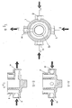
- Fig. 1 shows schematically the device.
- Fig.2 shows schematically the support mounting of the device with its retaining screw nut.
- Fig. 3 shows schematically the fuel reservoir and the device mounting with the elastic gasket which acts for their sealing.
- Fig.4 shows the inlet or outlet nipple, with the elastic gasket which is screwed in the thread of the mounting.
- Fig.5 is a cross section of the outlet plug of water-squalors, together with the elastic sealing gasket.
- Fig.6 is another view of the water-squalors outlet plug, with the threaded outlet duct not terminated at the lowest point, so as to achieve an effective clamping-sealing with the fuel reservoir.
- Fig. 7 is a top view of the water-squalors outlet plug.
- Fig.8 is a top view of the device mounting, where three possible inlets and one outlet thereof are depicted.
- Fig.9 shows the cross-sections A-A and B-B of the device mounting.
- Fig.10 shows the vertical layers of the uniformly joined together beads for forming the cone of the breaking up device.
- the device is placed as near as possible, near to the spraying system, and the fuel has to pass first through the cleaning filter so as to be absolutely clean for achieving the aims of the invention.
- the device Fig.1 is formed by the mounting (1) in which there are three closed inlets, among which the operator chooses the appropriate one, which will offer the best operation Fig.8, and one open outlet.
- the three inlets (8), (9), (10) and the outlet (11) of Fig.8 are cross shaped.
- the device mounting is metallic, but it can also be of plastic, and this is not restrictive.
- the fuel reservoir (5) Fig. 3 of 250gr. nominal capacity is screwed to the mounting (1) of the device through the elastic gasket (6), for fully sealing the said parts.
- the outlet plug Fig.5 of water-squalors (12) is screwed, the thread of which contains a duct of removing the refuse, this duct not covering the whole length of the thread, so as to achieve also, by the elastic gasket, the effective clamping-sealing of the fuel reservoir.
- the cone (14) is bolted for breaking up the fuel. It is created by uniform beads (15) of 0,001 to 0,999 ⁇ . diameter welded together. As material for making the beads a porous metal (bronze) is used, not excluding the use of plastic, glass and of any other adequate material.
- the beads are welded together in vertical layers, one to 200 or even more, creating thus a closed surface in the shape of a truncated cone (14), cylinder, closed washer, plate, or of any other adequate shape.
- the creation of the layers is accomplished as follows.
- the device is being placed on the vehicles' body with the help of the support mounting (16) Fig.2 and its retention is assured by the nut in the center of the mounting (1), so that the engineer can start the rotation of the engine in the best way he prefers.
- the device is loaded with fuel coming from the inlet of the metallic mounting, filling up the reservoir (5), and the fuel's volume is forced to pass through the whole mesh of the conically arranged metallic beads mentioned above.
- the molecules passing by the gaps of the layers are being rotated in order to find one of the three exit outlets and, in accordance with their diameter and weight, are being delayed inside the device until they leave the last layer. In this way the molecules are being controlled and at the exit from the device the molecular consistency of the fuel is changed.
Abstract
Description
- The present invention refers to a device for breaking up the volume of liquid fuels in order to achieve uniformity in the fuel molecules, so as to create a uniform molecular composition.
- In an internal-combustion engine (I.C. Engine) with a spraying supply system of gasoline-oil, the spraying (atomization) of the fuel is accomplished through atomizers. The atomized fuel forms a cloudy mass of air and gasoline droplets in the composition chamber.
- Up to now it is attempted the dispersion or spraying rate of the fuel to be proportional to the droplets number, which droplets are formed by a certain quantity of fuel broken up at the injection in the combustion chamber of the engine. It is aimed the number of these droplets, that is the dispersion degree of the fuel, to be as much as possible great, so that the exterior surface presented between fuel and air to be adequate for establishing a perfect combustion.
- If we take a sprayed droplet and examine it concerning its molecular composition, we will find that it consists of oxygen, carbon dioxide, hydrocarbon etc molecules, always in numerically greater quantities than one molecule and not equally spaced between them.
- This dissimilarity concerning the molecular composition and the unequal distances from the oxygen molecules in a sprayed droplet is the main reason why the internal combustion engines present their momentum in accordance with the increase of their revolutions (rpm) and that the maximum of their momentum is reached at a very high number of revolution.
- On the contrary, examining this theoretically, if we manage to put at the center of a sprayed droplet the oxygen molecule and to bring in touch with its perimeter the other molecules, and if we continuously spray to the internal combustion engine such droplets, the exploitation of the fuel would be perfect due to the uniform molecular composition, in relation to the engine efficiency.
- All this is known to the I.C. Engines supply system constructors, who, in order to solve this problem and to approach this theory:
- a) Increase the pressure of the atomizers,
- b) Increase the number of bores at the end of the atomizers,
- c) Change the inclination angles of the bores,
- d) Redesign and increase or decrease the intake tubes,
- e) Seek to achieve strong turbulence of the fuel before its entrance in the combustion chamber.
-
- They want the fuel not to be injected as a cylindrical column, but that its droplets be formed as a conically shaped cloud, which guarantees a better contact of the scattered droplets with the air, in other words the constructors try to split the sprayed fuel in more and smaller droplets.
- With the new type of our device for breaking up the volume of liquid fuels, we achieve the aim that the fuel entering the atomizers will consist of uniform molecules and that the droplets sprayed will consist of uniform molecules in correct ratio, so that the best possible combustion is achieved.
- The above and other features and advantages of the present invention will be evident from the following analytical description. The invention will be better understood by referring to the accompanying drawings which depict an embodiment thereof.
- Fig. 1 shows schematically the device.
- Fig.2 shows schematically the support mounting of the device with its retaining screw nut.
- Fig. 3 shows schematically the fuel reservoir and the device mounting with the elastic gasket which acts for their sealing.
- Fig.4 shows the inlet or outlet nipple, with the elastic gasket which is screwed in the thread of the mounting.
- Fig.5 is a cross section of the outlet plug of water-squalors, together with the elastic sealing gasket.
- Fig.6 is another view of the water-squalors outlet plug, with the threaded outlet duct not terminated at the lowest point, so as to achieve an effective clamping-sealing with the fuel reservoir.
- Fig. 7 is a top view of the water-squalors outlet plug.
- Fig.8 is a top view of the device mounting, where three possible inlets and one outlet thereof are depicted.
- Fig.9 shows the cross-sections A-A and B-B of the device mounting.
- Fig.10 shows the vertical layers of the uniformly joined together beads for forming the cone of the breaking up device.
- Referring now to the accompanying figures, we will describe an indicative preferable implementation of the invention. The device is placed as near as possible, near to the spraying system, and the fuel has to pass first through the cleaning filter so as to be absolutely clean for achieving the aims of the invention.
- The device Fig.1 is formed by the mounting (1) in which there are three closed inlets, among which the operator chooses the appropriate one, which will offer the best operation Fig.8, and one open outlet. The three inlets (8), (9), (10) and the outlet (11) of Fig.8 are cross shaped.
- The device mounting is metallic, but it can also be of plastic, and this is not restrictive. In the mounting thread are screwed, through the elastic gaskets (2) Fig.4, the two inlet (3) and outlet (4) nipples of the device Fig.1. The fuel reservoir (5) Fig. 3 of 250gr. nominal capacity is screwed to the mounting (1) of the device through the elastic gasket (6), for fully sealing the said parts. In the lowest part (7) of the fuel reservoir (5) the outlet plug Fig.5 of water-squalors (12) is screwed, the thread of which contains a duct of removing the refuse, this duct not covering the whole length of the thread, so as to achieve also, by the elastic gasket, the effective clamping-sealing of the fuel reservoir.
- Inside (13) the device mounting (1), the cone (14) is bolted for breaking up the fuel. It is created by uniform beads (15) of 0,001 to 0,999µ. diameter welded together. As material for making the beads a porous metal (bronze) is used, not excluding the use of plastic, glass and of any other adequate material.
- The beads are welded together in vertical layers, one to 200 or even more, creating thus a closed surface in the shape of a truncated cone (14), cylinder, closed washer, plate, or of any other adequate shape.
- The creation of the layers is accomplished as follows.
- After forming the first bead layer, in every gap produced in the center of four welded together beads a new bead is being welded creating thus a new layer. The same procedure is repeated for the gaps formed by the second layer creating thus the third layer and so on. Continuing doing this, we can form as many layers we wish.
- The device is being placed on the vehicles' body with the help of the support mounting (16) Fig.2 and its retention is assured by the nut in the center of the mounting (1), so that the engineer can start the rotation of the engine in the best way he prefers.
- The device is loaded with fuel coming from the inlet of the metallic mounting, filling up the reservoir (5), and the fuel's volume is forced to pass through the whole mesh of the conically arranged metallic beads mentioned above.
- By passing through the gaps of the first layer, the breaking up of the fuel's volume is achieved. The molecules passing through the gaps of the first layer to continue to the second one have three exit outlets, and the same happens in every layer.
- The molecules passing by the gaps of the layers are being rotated in order to find one of the three exit outlets and, in accordance with their diameter and weight, are being delayed inside the device until they leave the last layer. In this way the molecules are being controlled and at the exit from the device the molecular consistency of the fuel is changed.
- The main advantages obtained with the device during the operation of the engine are:
- Increase of the momentum.
- The maximum momentum is obtained at lower revolutions of the engine, and the width of the maximum momentum is maintained constant for a greater number of revolutions.
- The horse-power of the engine is increased.
- The combustion is clean.
- Squalors are decreased.
- The engine's noise is less.
- The engine's temperature is constant, resulting in less wear and longer life of the engine.
- It must be noted that the description of the invention was made in the way of a non limiting exemplary embodiment. Any change or modification concerning the shapes, dimensions, and materials used for the construction and the assembly, if they do not form a new inventing step are considered to be included within the scope and aims of the present invention.
Claims (7)
- Device for breaking up the volume of liquid fuels in order to achieve a uniform molecular composition, characterized by that it is consisting of the mounting (1) with three closed intakes, and the engineer can choose to open the one that suits him/her more, and with one open outlet, all of which are cross shaped, where in the mounting thread the two intake (3) and outlet (4) nipples of the device are screwed, and of the fuel reservoir (5), at the lowest point (7) of which the water-squalors outlet plug (12) is being screwed, whose thread has a duct for the exit of the refuse, by that in the interior (13) of the mounting the cone (14) is screwed for obtaining the fuel breaking up, and by that with this device we obtain the result that the fuel channeled to the atomizer will consist of uniform molecules and that the droplets sprayed will have the correct ratio of molecules for achieving the best possible combustion.
- Device for breaking up the volume of liquid fuels in order to achieve a uniform molecular composition in accordance with the above claim 1, characterized by that this device is placed as near as possible to the spraying system, and by that the fuel has first to pass through the purification system so that it is perfectly clean for attaining the aims of the device.
- Device for breaking up the volume of liquid fuels in order to achieve a uniform molecular composition in accordance with the above claim 1, characterized by that the device mounting can be of metal, plastic or of any other suitable material, and by that in this mounting the fuel reservoir (5) of indicative capacity of 250gr. is screwed through the elastic gasket (6), for its full sealing.
- Device for breaking up the volume of liquid fuels in order to achieve a uniform molecular composition in accordance with the above claim 1, characterized by that the thread of the water-squalor (12) outlet plug has a duct not fully covering the length of the thread, so as to obtain an effective clamping-sealing with the fuel reservoir by means of the elastic gasket.
- Device for breaking up the volume of liquid fuels in order to achieve a uniform molecular composition in accordance with the above claim 1, characterized by that the cone (14) which acts for the breaking up of the fuel is created by uniform beads (15) of 0,001-0,999µ. diameter welded together, and by that as material a porous metal is used, not excluding the use of plastic, glass or of any other adequate material.
- Device for breaking up the volume of liquid fuels in order to achieve a uniform molecular composition in accordance with the above claim 1, characterized by that the beads for forming the cone are welded together in vertical layers, from one to 200 or even more, producing a closed surface of conical, cylindrical, closed washer, plate or of any other adequate shape, and by that after creating the first bead layer in every gap formed in the center of four welded together beads a new bead is being welded establishing thus a second bead layer, and the same procedure is repeated at the gaps resulting from the beads of the second layer, resulting in a third layer, and so on, creating thus as many layers we wish.
- Device for breaking up the volume of liquid fuels in order to achieve a uniform molecular composition in accordance with the above claim 1, characterized by that the device is loaded with fuel entering from the inlet of the metal mounting and filling the reservoir (5), by that the fuel has to pass through the whole mesh of the metal beads, by that the passage through the gaps of the first layer produces the breaking up of the fuel volume, by that the molecules passing through the gaps of the first layer on their way to the second layer have three exit outlets, and the same happens with every other layer, and by that when the molecules pass through the gaps they are being rotated in order to find one of the three exit outlets and depending on their diameter and weight, they are delayed within the device until they can find the last layer, and in this way the molecules are being controlled and at the exit of the device the molecular composition will have changed.
Applications Claiming Priority (2)
| Application Number | Priority Date | Filing Date | Title |
|---|---|---|---|
| GR2004100071 | 2004-02-26 | ||
| GR20040100071A GR1004707B (en) | 2004-02-26 | 2004-02-26 | Liquid fuel-fissioning device for obtaining uniform molecular composition for same fuel |
Publications (2)
| Publication Number | Publication Date |
|---|---|
| EP1568879A2 true EP1568879A2 (en) | 2005-08-31 |
| EP1568879A3 EP1568879A3 (en) | 2012-03-28 |
Family
ID=33446258
Family Applications (1)
| Application Number | Title | Priority Date | Filing Date |
|---|---|---|---|
| EP05386002A Withdrawn EP1568879A3 (en) | 2004-02-26 | 2005-01-24 | Device for breaking up the volume of liquid fuels in order to achieve a uniform molecular composition |
Country Status (2)
| Country | Link |
|---|---|
| EP (1) | EP1568879A3 (en) |
| GR (1) | GR1004707B (en) |
Citations (3)
| Publication number | Priority date | Publication date | Assignee | Title |
|---|---|---|---|---|
| GB2023226A (en) | 1978-06-14 | 1979-12-28 | Daimler Benz Ag | Multiple-cylinder internal combustion engine |
| US4257890A (en) | 1979-07-25 | 1981-03-24 | Hurner Erwin E | Fuel-water separator |
| US5227061A (en) | 1992-01-13 | 1993-07-13 | Bedsole Robert D | Fuel/contaminant separator |
Family Cites Families (2)
| Publication number | Priority date | Publication date | Assignee | Title |
|---|---|---|---|---|
| US3622007A (en) * | 1969-07-24 | 1971-11-23 | Gen Metal Products Corp | Fuel filter |
| US4088104A (en) * | 1975-07-10 | 1978-05-09 | Ibbott Jack Kenneth | Device and method for improving vaporization rate of volatile fuels |
-
2004
- 2004-02-26 GR GR20040100071A patent/GR1004707B/en unknown
-
2005
- 2005-01-24 EP EP05386002A patent/EP1568879A3/en not_active Withdrawn
Patent Citations (3)
| Publication number | Priority date | Publication date | Assignee | Title |
|---|---|---|---|---|
| GB2023226A (en) | 1978-06-14 | 1979-12-28 | Daimler Benz Ag | Multiple-cylinder internal combustion engine |
| US4257890A (en) | 1979-07-25 | 1981-03-24 | Hurner Erwin E | Fuel-water separator |
| US5227061A (en) | 1992-01-13 | 1993-07-13 | Bedsole Robert D | Fuel/contaminant separator |
Also Published As
| Publication number | Publication date |
|---|---|
| EP1568879A3 (en) | 2012-03-28 |
| GR1004707B (en) | 2004-10-25 |
Similar Documents
| Publication | Publication Date | Title |
|---|---|---|
| US7077341B2 (en) | Fuel injection device | |
| US4515133A (en) | Fuel economizing device | |
| EP0159189B1 (en) | Ultrasonic vibration method and apparatus for atomizing liquid material | |
| US5898560A (en) | Static discharge device for electrically non-conductive fluids | |
| JP2002528671A (en) | Mixture mixing equipment for engines | |
| JP2013532247A (en) | Multiphysics fuel spray apparatus and method | |
| US6817347B2 (en) | Fuel converter | |
| US4082070A (en) | Installation for feeding and atomizing liquid, especially combustion fuel | |
| JP2013199932A (en) | Induction regulator block | |
| US6748921B1 (en) | Reversion redirection device for an internal combustion engine | |
| EP1568879A2 (en) | Device for breaking up the volume of liquid fuels in order to achieve a uniform molecular composition | |
| US20160319793A1 (en) | Nozzle Head and Fluid Injection Valve | |
| CN1220370A (en) | Method and device for injecting fuel/liquid mixture into combustion chamber of burner | |
| CN105378264B (en) | Fuel injection valve for combustion engine | |
| CN2908813Y (en) | Swirl spray hymidifying tower | |
| US3653643A (en) | Carburetor | |
| CA2046863A1 (en) | Process for optimising fuel combustion with the minimum co emission and device for implementing it | |
| CN1064740C (en) | IC engine fuel supply system | |
| US4163436A (en) | Gasoline miser | |
| US5937838A (en) | Fuel vaporizing system for internal combustion engines | |
| CN108005826B (en) | Frequency conversion fuel sprayer | |
| CN105275698B (en) | A kind of engine variable-frequency fuel-injection mouth | |
| JPH09228908A (en) | Intake device of gasoline engine | |
| US2838362A (en) | Apparatus for atomizing liquids | |
| SU1643769A1 (en) | Air cleaner for internal combustion engine of transport facilities |
Legal Events
| Date | Code | Title | Description |
|---|---|---|---|
| PUAI | Public reference made under article 153(3) epc to a published international application that has entered the european phase |
Free format text: ORIGINAL CODE: 0009012 |
|
| AK | Designated contracting states |
Kind code of ref document: A2 Designated state(s): AT BE BG CH CY CZ DE DK EE ES FI FR GB GR HU IE IS IT LI LT LU MC NL PL PT RO SE SI SK TR |
|
| AX | Request for extension of the european patent |
Extension state: AL BA HR LV MK YU |
|
| PUAL | Search report despatched |
Free format text: ORIGINAL CODE: 0009013 |
|
| AK | Designated contracting states |
Kind code of ref document: A3 Designated state(s): AT BE BG CH CY CZ DE DK EE ES FI FR GB GR HU IE IS IT LI LT LU MC NL PL PT RO SE SI SK TR |
|
| AX | Request for extension of the european patent |
Extension state: AL BA HR LV MK YU |
|
| RIC1 | Information provided on ipc code assigned before grant |
Ipc: F02M 33/00 20060101ALI20120220BHEP Ipc: F02M 37/22 20060101ALI20120220BHEP Ipc: F02M 29/04 20060101AFI20120220BHEP |
|
| 17P | Request for examination filed |
Effective date: 20120907 |
|
| AKX | Designation fees paid |
Designated state(s): AT BE BG CH CY CZ DE DK EE ES FI FR GB GR HU IE IS IT LI LT LU MC NL PL PT RO SE SI SK TR |
|
| 17Q | First examination report despatched |
Effective date: 20130207 |
|
| GRAP | Despatch of communication of intention to grant a patent |
Free format text: ORIGINAL CODE: EPIDOSNIGR1 |
|
| INTG | Intention to grant announced |
Effective date: 20150312 |
|
| INTG | Intention to grant announced |
Effective date: 20150316 |
|
| STAA | Information on the status of an ep patent application or granted ep patent |
Free format text: STATUS: THE APPLICATION IS DEEMED TO BE WITHDRAWN |
|
| 18D | Application deemed to be withdrawn |
Effective date: 20150728 |