EP1568879A2 - Vorrichtung zum Aufteilen des Volumens von flüssigem Brennstoff zum Erreichen von einer gleichartigen Molekularzusammensetzung - Google Patents
Vorrichtung zum Aufteilen des Volumens von flüssigem Brennstoff zum Erreichen von einer gleichartigen Molekularzusammensetzung Download PDFInfo
- Publication number
- EP1568879A2 EP1568879A2 EP05386002A EP05386002A EP1568879A2 EP 1568879 A2 EP1568879 A2 EP 1568879A2 EP 05386002 A EP05386002 A EP 05386002A EP 05386002 A EP05386002 A EP 05386002A EP 1568879 A2 EP1568879 A2 EP 1568879A2
- Authority
- EP
- European Patent Office
- Prior art keywords
- breaking
- fuel
- volume
- achieve
- molecular composition
- Prior art date
- Legal status (The legal status is an assumption and is not a legal conclusion. Google has not performed a legal analysis and makes no representation as to the accuracy of the status listed.)
- Withdrawn
Links
- 239000000446 fuel Substances 0.000 title claims abstract description 46
- 239000000203 mixture Substances 0.000 title claims abstract description 15
- 239000007788 liquid Substances 0.000 title claims abstract description 11
- 239000011324 bead Substances 0.000 claims abstract description 17
- 238000002485 combustion reaction Methods 0.000 claims abstract description 11
- 239000002184 metal Substances 0.000 claims abstract description 6
- 238000007789 sealing Methods 0.000 claims description 7
- 239000000463 material Substances 0.000 claims description 6
- 238000005507 spraying Methods 0.000 claims description 5
- 210000002445 nipple Anatomy 0.000 claims description 3
- 230000003111 delayed effect Effects 0.000 claims description 2
- 239000011521 glass Substances 0.000 claims description 2
- 238000000034 method Methods 0.000 claims description 2
- 238000000746 purification Methods 0.000 claims 1
- 239000006185 dispersion Substances 0.000 description 2
- 229910000906 Bronze Inorganic materials 0.000 description 1
- 239000004215 Carbon black (E152) Substances 0.000 description 1
- MYMOFIZGZYHOMD-UHFFFAOYSA-N Dioxygen Chemical compound O=O MYMOFIZGZYHOMD-UHFFFAOYSA-N 0.000 description 1
- QVGXLLKOCUKJST-UHFFFAOYSA-N atomic oxygen Chemical compound [O] QVGXLLKOCUKJST-UHFFFAOYSA-N 0.000 description 1
- 238000000889 atomisation Methods 0.000 description 1
- 239000010974 bronze Substances 0.000 description 1
- UBAZGMLMVVQSCD-UHFFFAOYSA-N carbon dioxide;molecular oxygen Chemical compound O=O.O=C=O UBAZGMLMVVQSCD-UHFFFAOYSA-N 0.000 description 1
- 238000004140 cleaning Methods 0.000 description 1
- 238000010276 construction Methods 0.000 description 1
- KUNSUQLRTQLHQQ-UHFFFAOYSA-N copper tin Chemical compound [Cu].[Sn] KUNSUQLRTQLHQQ-UHFFFAOYSA-N 0.000 description 1
- 230000003247 decreasing effect Effects 0.000 description 1
- 229930195733 hydrocarbon Natural products 0.000 description 1
- 150000002430 hydrocarbons Chemical class 0.000 description 1
- 238000002347 injection Methods 0.000 description 1
- 239000007924 injection Substances 0.000 description 1
- 230000014759 maintenance of location Effects 0.000 description 1
- 230000004048 modification Effects 0.000 description 1
- 238000012986 modification Methods 0.000 description 1
- 229910052760 oxygen Inorganic materials 0.000 description 1
- 239000001301 oxygen Substances 0.000 description 1
- 239000007921 spray Substances 0.000 description 1
Images


Classifications
-
- F—MECHANICAL ENGINEERING; LIGHTING; HEATING; WEAPONS; BLASTING
- F02—COMBUSTION ENGINES; HOT-GAS OR COMBUSTION-PRODUCT ENGINE PLANTS
- F02M—SUPPLYING COMBUSTION ENGINES IN GENERAL WITH COMBUSTIBLE MIXTURES OR CONSTITUENTS THEREOF
- F02M29/00—Apparatus for re-atomising condensed fuel or homogenising fuel-air mixture
- F02M29/04—Apparatus for re-atomising condensed fuel or homogenising fuel-air mixture having screens, gratings, baffles or the like
-
- F—MECHANICAL ENGINEERING; LIGHTING; HEATING; WEAPONS; BLASTING
- F02—COMBUSTION ENGINES; HOT-GAS OR COMBUSTION-PRODUCT ENGINE PLANTS
- F02M—SUPPLYING COMBUSTION ENGINES IN GENERAL WITH COMBUSTIBLE MIXTURES OR CONSTITUENTS THEREOF
- F02M33/00—Other apparatus for treating combustion-air, fuel or fuel-air mixture
-
- F—MECHANICAL ENGINEERING; LIGHTING; HEATING; WEAPONS; BLASTING
- F02—COMBUSTION ENGINES; HOT-GAS OR COMBUSTION-PRODUCT ENGINE PLANTS
- F02M—SUPPLYING COMBUSTION ENGINES IN GENERAL WITH COMBUSTIBLE MIXTURES OR CONSTITUENTS THEREOF
- F02M37/00—Apparatus or systems for feeding liquid fuel from storage containers to carburettors or fuel-injection apparatus; Arrangements for purifying liquid fuel specially adapted for, or arranged on, internal-combustion engines
- F02M37/22—Arrangements for purifying liquid fuel specially adapted for, or arranged on, internal-combustion engines, e.g. arrangements in the feeding system
- F02M37/24—Arrangements for purifying liquid fuel specially adapted for, or arranged on, internal-combustion engines, e.g. arrangements in the feeding system characterised by water separating means
-
- F—MECHANICAL ENGINEERING; LIGHTING; HEATING; WEAPONS; BLASTING
- F02—COMBUSTION ENGINES; HOT-GAS OR COMBUSTION-PRODUCT ENGINE PLANTS
- F02M—SUPPLYING COMBUSTION ENGINES IN GENERAL WITH COMBUSTIBLE MIXTURES OR CONSTITUENTS THEREOF
- F02M37/00—Apparatus or systems for feeding liquid fuel from storage containers to carburettors or fuel-injection apparatus; Arrangements for purifying liquid fuel specially adapted for, or arranged on, internal-combustion engines
- F02M37/22—Arrangements for purifying liquid fuel specially adapted for, or arranged on, internal-combustion engines, e.g. arrangements in the feeding system
- F02M37/32—Arrangements for purifying liquid fuel specially adapted for, or arranged on, internal-combustion engines, e.g. arrangements in the feeding system characterised by filters or filter arrangements
Definitions
- the present invention refers to a device for breaking up the volume of liquid fuels in order to achieve uniformity in the fuel molecules, so as to create a uniform molecular composition.
- an internal-combustion engine (I.C. Engine) with a spraying supply system of gasoline-oil
- the spraying (atomization) of the fuel is accomplished through atomizers.
- the atomized fuel forms a cloudy mass of air and gasoline droplets in the composition chamber.
- the dispersion or spraying rate of the fuel is proportional to the droplets number, which droplets are formed by a certain quantity of fuel broken up at the injection in the combustion chamber of the engine. It is aimed the number of these droplets, that is the dispersion degree of the fuel, to be as much as possible great, so that the exterior surface presented between fuel and air to be adequate for establishing a perfect combustion.
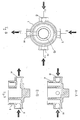
- Fig. 1 shows schematically the device.
- Fig.2 shows schematically the support mounting of the device with its retaining screw nut.
- Fig. 3 shows schematically the fuel reservoir and the device mounting with the elastic gasket which acts for their sealing.
- Fig.4 shows the inlet or outlet nipple, with the elastic gasket which is screwed in the thread of the mounting.
- Fig.5 is a cross section of the outlet plug of water-squalors, together with the elastic sealing gasket.
- Fig.6 is another view of the water-squalors outlet plug, with the threaded outlet duct not terminated at the lowest point, so as to achieve an effective clamping-sealing with the fuel reservoir.
- Fig. 7 is a top view of the water-squalors outlet plug.
- Fig.8 is a top view of the device mounting, where three possible inlets and one outlet thereof are depicted.
- Fig.9 shows the cross-sections A-A and B-B of the device mounting.
- Fig.10 shows the vertical layers of the uniformly joined together beads for forming the cone of the breaking up device.
- the device is placed as near as possible, near to the spraying system, and the fuel has to pass first through the cleaning filter so as to be absolutely clean for achieving the aims of the invention.
- the device Fig.1 is formed by the mounting (1) in which there are three closed inlets, among which the operator chooses the appropriate one, which will offer the best operation Fig.8, and one open outlet.
- the three inlets (8), (9), (10) and the outlet (11) of Fig.8 are cross shaped.
- the device mounting is metallic, but it can also be of plastic, and this is not restrictive.
- the fuel reservoir (5) Fig. 3 of 250gr. nominal capacity is screwed to the mounting (1) of the device through the elastic gasket (6), for fully sealing the said parts.
- the outlet plug Fig.5 of water-squalors (12) is screwed, the thread of which contains a duct of removing the refuse, this duct not covering the whole length of the thread, so as to achieve also, by the elastic gasket, the effective clamping-sealing of the fuel reservoir.
- the cone (14) is bolted for breaking up the fuel. It is created by uniform beads (15) of 0,001 to 0,999 ⁇ . diameter welded together. As material for making the beads a porous metal (bronze) is used, not excluding the use of plastic, glass and of any other adequate material.
- the beads are welded together in vertical layers, one to 200 or even more, creating thus a closed surface in the shape of a truncated cone (14), cylinder, closed washer, plate, or of any other adequate shape.
- the creation of the layers is accomplished as follows.
- the device is being placed on the vehicles' body with the help of the support mounting (16) Fig.2 and its retention is assured by the nut in the center of the mounting (1), so that the engineer can start the rotation of the engine in the best way he prefers.
- the device is loaded with fuel coming from the inlet of the metallic mounting, filling up the reservoir (5), and the fuel's volume is forced to pass through the whole mesh of the conically arranged metallic beads mentioned above.
- the molecules passing by the gaps of the layers are being rotated in order to find one of the three exit outlets and, in accordance with their diameter and weight, are being delayed inside the device until they leave the last layer. In this way the molecules are being controlled and at the exit from the device the molecular consistency of the fuel is changed.
Landscapes
- Engineering & Computer Science (AREA)
- Chemical & Material Sciences (AREA)
- Combustion & Propulsion (AREA)
- Mechanical Engineering (AREA)
- General Engineering & Computer Science (AREA)
- Fuel-Injection Apparatus (AREA)
- Monitoring And Testing Of Nuclear Reactors (AREA)
- Output Control And Ontrol Of Special Type Engine (AREA)
Applications Claiming Priority (2)
| Application Number | Priority Date | Filing Date | Title |
|---|---|---|---|
| GR20040100071A GR1004707B (el) | 2004-02-26 | 2004-02-26 | Συσκευη διασπασης ογκου υγρων καυσιμων για την επιτευξη ομοιομορφης μοριακης συνθεσης |
| GR2004100071 | 2004-02-26 |
Publications (2)
| Publication Number | Publication Date |
|---|---|
| EP1568879A2 true EP1568879A2 (de) | 2005-08-31 |
| EP1568879A3 EP1568879A3 (de) | 2012-03-28 |
Family
ID=33446258
Family Applications (1)
| Application Number | Title | Priority Date | Filing Date |
|---|---|---|---|
| EP05386002A Withdrawn EP1568879A3 (de) | 2004-02-26 | 2005-01-24 | Vorrichtung zum Aufteilen des Volumens von flüssigem Brennstoff zum Erreichen von einer gleichartigen Molekularzusammensetzung |
Country Status (2)
| Country | Link |
|---|---|
| EP (1) | EP1568879A3 (de) |
| GR (1) | GR1004707B (de) |
Citations (3)
| Publication number | Priority date | Publication date | Assignee | Title |
|---|---|---|---|---|
| GB2023226A (en) | 1978-06-14 | 1979-12-28 | Daimler Benz Ag | Multiple-cylinder internal combustion engine |
| US4257890A (en) | 1979-07-25 | 1981-03-24 | Hurner Erwin E | Fuel-water separator |
| US5227061A (en) | 1992-01-13 | 1993-07-13 | Bedsole Robert D | Fuel/contaminant separator |
Family Cites Families (2)
| Publication number | Priority date | Publication date | Assignee | Title |
|---|---|---|---|---|
| US3622007A (en) * | 1969-07-24 | 1971-11-23 | Gen Metal Products Corp | Fuel filter |
| US4088104A (en) * | 1975-07-10 | 1978-05-09 | Ibbott Jack Kenneth | Device and method for improving vaporization rate of volatile fuels |
-
2004
- 2004-02-26 GR GR20040100071A patent/GR1004707B/el unknown
-
2005
- 2005-01-24 EP EP05386002A patent/EP1568879A3/de not_active Withdrawn
Patent Citations (3)
| Publication number | Priority date | Publication date | Assignee | Title |
|---|---|---|---|---|
| GB2023226A (en) | 1978-06-14 | 1979-12-28 | Daimler Benz Ag | Multiple-cylinder internal combustion engine |
| US4257890A (en) | 1979-07-25 | 1981-03-24 | Hurner Erwin E | Fuel-water separator |
| US5227061A (en) | 1992-01-13 | 1993-07-13 | Bedsole Robert D | Fuel/contaminant separator |
Also Published As
| Publication number | Publication date |
|---|---|
| GR1004707B (el) | 2004-10-25 |
| EP1568879A3 (de) | 2012-03-28 |
Similar Documents
| Publication | Publication Date | Title |
|---|---|---|
| US4515133A (en) | Fuel economizing device | |
| US7077341B2 (en) | Fuel injection device | |
| EP0159189B1 (de) | Verfahren zur Ultraschallschwingung und Vorrichtung zur Zerstäubung von Flüssigkeit | |
| JP2002528671A (ja) | エンジン用混合気混合装置 | |
| WO1999003552A2 (en) | A static discharge device for electrically non-conductive fluids | |
| US6817347B2 (en) | Fuel converter | |
| CA2046863A1 (en) | Process for optimising fuel combustion with the minimum co emission and device for implementing it | |
| KR101908826B1 (ko) | 노즐 헤드 및 유체 분사 밸브 | |
| JP2013199932A (ja) | インダクション・レギュレータブロック | |
| US6748921B1 (en) | Reversion redirection device for an internal combustion engine | |
| EP1568879A2 (de) | Vorrichtung zum Aufteilen des Volumens von flüssigem Brennstoff zum Erreichen von einer gleichartigen Molekularzusammensetzung | |
| CN2173311Y (zh) | 液体喷射雾化喷嘴 | |
| CN102465739B (zh) | 喷射器 | |
| CN1149329A (zh) | 内燃机燃油供给装置 | |
| RU2337287C1 (ru) | Распылительная сушилка с акустической форсункой | |
| US5937838A (en) | Fuel vaporizing system for internal combustion engines | |
| RU2327895C2 (ru) | Фильтр магнитной очистки и обработки автомобильного и авиационного топлива экомаг-10г | |
| CN108005826B (zh) | 一种变频喷油嘴 | |
| CN206439092U (zh) | 一种用于柴油机排气后处理再生装置的匀流板 | |
| CN119779683B (zh) | 一种视窗可更换的控温控压定容弹 | |
| US2838362A (en) | Apparatus for atomizing liquids | |
| SU1643769A1 (ru) | Воздухоочиститель дл двигател внутреннего сгорани транспортного средства | |
| GB2051237A (en) | Low Pressure Throttle Body Injection Apparatus | |
| KR0126296Y1 (ko) | 내연기관의 연료 2차 무화장치 | |
| US1377756A (en) | Atomizing-nozzle |
Legal Events
| Date | Code | Title | Description |
|---|---|---|---|
| PUAI | Public reference made under article 153(3) epc to a published international application that has entered the european phase |
Free format text: ORIGINAL CODE: 0009012 |
|
| AK | Designated contracting states |
Kind code of ref document: A2 Designated state(s): AT BE BG CH CY CZ DE DK EE ES FI FR GB GR HU IE IS IT LI LT LU MC NL PL PT RO SE SI SK TR |
|
| AX | Request for extension of the european patent |
Extension state: AL BA HR LV MK YU |
|
| PUAL | Search report despatched |
Free format text: ORIGINAL CODE: 0009013 |
|
| AK | Designated contracting states |
Kind code of ref document: A3 Designated state(s): AT BE BG CH CY CZ DE DK EE ES FI FR GB GR HU IE IS IT LI LT LU MC NL PL PT RO SE SI SK TR |
|
| AX | Request for extension of the european patent |
Extension state: AL BA HR LV MK YU |
|
| RIC1 | Information provided on ipc code assigned before grant |
Ipc: F02M 33/00 20060101ALI20120220BHEP Ipc: F02M 37/22 20060101ALI20120220BHEP Ipc: F02M 29/04 20060101AFI20120220BHEP |
|
| 17P | Request for examination filed |
Effective date: 20120907 |
|
| AKX | Designation fees paid |
Designated state(s): AT BE BG CH CY CZ DE DK EE ES FI FR GB GR HU IE IS IT LI LT LU MC NL PL PT RO SE SI SK TR |
|
| 17Q | First examination report despatched |
Effective date: 20130207 |
|
| GRAP | Despatch of communication of intention to grant a patent |
Free format text: ORIGINAL CODE: EPIDOSNIGR1 |
|
| INTG | Intention to grant announced |
Effective date: 20150312 |
|
| INTG | Intention to grant announced |
Effective date: 20150316 |
|
| STAA | Information on the status of an ep patent application or granted ep patent |
Free format text: STATUS: THE APPLICATION IS DEEMED TO BE WITHDRAWN |
|
| 18D | Application deemed to be withdrawn |
Effective date: 20150728 |