EP1568862A2 - Fingerförmiges Klappenventil - Google Patents
Fingerförmiges Klappenventil Download PDFInfo
- Publication number
- EP1568862A2 EP1568862A2 EP05011547A EP05011547A EP1568862A2 EP 1568862 A2 EP1568862 A2 EP 1568862A2 EP 05011547 A EP05011547 A EP 05011547A EP 05011547 A EP05011547 A EP 05011547A EP 1568862 A2 EP1568862 A2 EP 1568862A2
- Authority
- EP
- European Patent Office
- Prior art keywords
- flapper
- flapper valve
- flapper finger
- exhaust
- tube
- Prior art date
- Legal status (The legal status is an assumption and is not a legal conclusion. Google has not performed a legal analysis and makes no representation as to the accuracy of the status listed.)
- Granted
Links
Images



Classifications
-
- F—MECHANICAL ENGINEERING; LIGHTING; HEATING; WEAPONS; BLASTING
- F01—MACHINES OR ENGINES IN GENERAL; ENGINE PLANTS IN GENERAL; STEAM ENGINES
- F01N—GAS-FLOW SILENCERS OR EXHAUST APPARATUS FOR MACHINES OR ENGINES IN GENERAL; GAS-FLOW SILENCERS OR EXHAUST APPARATUS FOR INTERNAL-COMBUSTION ENGINES
- F01N1/00—Silencing apparatus characterised by method of silencing
- F01N1/16—Silencing apparatus characterised by method of silencing by using movable parts
- F01N1/165—Silencing apparatus characterised by method of silencing by using movable parts for adjusting flow area
-
- F—MECHANICAL ENGINEERING; LIGHTING; HEATING; WEAPONS; BLASTING
- F01—MACHINES OR ENGINES IN GENERAL; ENGINE PLANTS IN GENERAL; STEAM ENGINES
- F01N—GAS-FLOW SILENCERS OR EXHAUST APPARATUS FOR MACHINES OR ENGINES IN GENERAL; GAS-FLOW SILENCERS OR EXHAUST APPARATUS FOR INTERNAL-COMBUSTION ENGINES
- F01N1/00—Silencing apparatus characterised by method of silencing
- F01N1/08—Silencing apparatus characterised by method of silencing by reducing exhaust energy by throttling or whirling
Definitions
- the invention broadly relates to exhaust systems and mufflers, and more particularly relates to a flapper finger valve and a flapper finger valve assembly that will be used in an automotive exhaust system to define a flow path for exhaust gasses that are released under high pressure and high flow conditions.
- mufflers are stamped from typically known steel, aluminum or the like and will use multiple internal baffles and tubes to silence the exhaust noise from the power train.
- exhaust enters one end of a muffler and is moved through a series of baffles and tubes in the interior of the muffler, to an exhaust tube and then on to a tailpipe.
- the design of the baffles, the number of baffles, the holes in the baffles, and any piping within the muffler all relate to the pressure and flow conditions through the muffler and exhaust system of the automotive vehicle.
- the size of the prior art muffler and exhaust systems of automotive vehicles is rather large in order to accomplish the baffling and noise reduction required by the muffler systems.
- the size of the exhaust systems require a lot of the packaging room available on the undercarriage of the chassis system of the automotive vehicles.
- the tuning and control of other characteristics of the muffler also can increase the performance and other associated characteristics of the automotive vehicle depending on the design of the baffles and the amount of pressure allowed to be released and at what flow rate the pressure is released through the exhaust system. Therefore, the performance characteristics of the vehicle that are effected by the release of pressure through the exhaust system in many prior art vehicles is fixed once the exhaust system is installed. Hence, the size of the muffler had to be large to correctly tune and dampen noise as required by the exhaust muffler system.
- An aim of the present invention is to provide a low cost flapper finger valve and flapper finger valve assembly which defines a flow path for the exhaust gasses of an exhaust system to be released under high pressure or high flow conditions.
- Another aim of the present invention is to provide an exhaust system that is capable of a variety of configurations to control and/or fine tune the exhaust system per application requirements of the motor vehicle characteristics.
- Still another aim of the present invention is to provide an exhaust system that includes a muffler with a smaller package thus reducing the amount of room used on the chassis underbody.
- Still another aim of the present invention is to provide flapper finger valve assembly that can independently operate or operate within an existing muffler to regulate the flow path for exhaust gasses in an exhaust system of an automotive vehicle.
- the foregoing and other aims are obtained by a novel design for a flapper finger valve assembly for use in an automotive exhaust system.
- the flapper finger valve assembly would either be an independent mechanism or integrated into an assembly for a muffler or exhaust system to create and regulate flow through a path for exhaust gasses to be released under high pressure and high flow conditions in the exhaust system.
- the flapper finger valve assembly includes at least one flapper finger valve connected to an exhaust tube and an exhaust pressure relief valve retainer or backer.
- One advantage of the above aspect of the present invention is an improved exhaust or muffler system.
- Still another advantage of the above aspect of the present invention is to create an escape path for exhaust gases to be released under high pressure and flow conditions.
- Still another advantage of the above aspect of the present invention is the reduction in overall size and packaging requirements for the exhaust system of an automotive vehicle.
- Yet another advantage of the above aspect of the present invention is the reduction in weight of the exhaust system for the vehicle.
- Still another advantage of the above aspect of the present invention is the tuneability and variability of the exhaust system by changing design requirements of the flapper finger valves.
- the invention provides an exhaust system, said system including:
- the invention also provides, a muffler for use in an exhaust system, said muffler including:
- said flapper finger valve assembly has a tube.
- said tube has a plurality of orifices therethrough.
- said flapper finger valve assembly system has at least one flapper finger valve, said flapper finger valve having a generally C-shape.
- said flapper finger valve is arranged around said tube, said flapper finger valve covers said orifices when said flapper finger valve is in a closed position.
- said flapper finger valve has a predetermined spring coefficient.
- said flapper finger valve moves in a radially outward direction when exposed to a predetermined pressure.
- said flapper finger valve is capable of being tuned to specific exhaust system characteristics.
- said flapper finger valve has predetermined angled bends, thicknesses and widths.
- said flapper finger valve assembly system has at least one relief valve retainer, said relief valve retainer generally having a C-shape.
- said flapper finger valve assembly is electronically controlled and tunable.
- the flapper finger valve assembly has a plurality of flapper finger valves arranged around an outer surface of said tube, said flapper finger valves covering said orifices when said flapper finger valve assembly is in a closed position.
- the flapper finger valve assembly has a plurality of relief backers arranged around said flapper finger valves to control a maximum distance of radial movement in an outward direction for said flapper finger valve.
- the flapper finger valves and said relief backers are secured to an outer surface of said tube.
- the flapper finger valves having a predetermined thickness and spring coefficient, said flapper finger valves being arranged to open or move radially away from said tube at predetermined exhaust pressures.
- the flapper finger valves are electronically controllable or tunable.
- a plurality of said flapper finger valve assemblies are arranged within a reduced size muffler in parallel or series.
- the invention also provides a flapper finger valve assembly for use in an exhaust system, said assembly including:
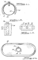
- Figs. 1 through 14 show the flapper finger valve assembly 10 according to the present invention.
- the flapper finger valve assembly 10 will be for use on a muffler or exhaust system component 38 and/or as a stand alone unit that will allow for the propagation of the exhaust gasses through a predetermined path for release under high pressure and high flow conditions.
- the use of the flapper finger valve assembly 10 will allow for a reduction in the packaging size of the muffler 38 thus increasing available space on the undercarriage of the chassis of an automotive vehicle. Furthermore the reduction in size will also reduce the weight and manufacturing costs of the muffler or exhaust system 38.
- the flapper finger valve assembly 10 will be available in a variety of configurations and will also allow for a variable control or fine tuning of the exhaust system and power train of the vehicle.
- Fig. 1 shows the exhaust pressure flapper finger valve or relief valve 12 according to the present invention.
- the flapper finger valve 12 has an overall C-shape.
- the valve 12 has an orifice 14 through a surface thereof at or near a top point thereof.
- Fig. 1 shows the valve in a closed position 16 and in an open position 18.
- the flapper finger valve 12 will be made of a steel material that will have a predetermined spring coefficient. It should be noted that any other type of metal, ceramic, plastic, composite or any other type of material may be used for the flapper finger valve 12. As shown in Fig.
- the flapper finger valve 12 also includes, on both ends thereof, a predetermined bend 20 at a predetermined angle which will be used to cover and seal a predetermined orifice 22 in the exhaust system.
- the flapper finger valve 12 is designed such that it controls the release of the exhaust pressure and flow of the exhaust in a predetermined manner.
- the steel will have a predetermined spring coefficient that in one embodiment will be in the closed position in its equilibrium position. Then when a predetermined pressure from the exhaust is placed upon an inner surface of the flapper finger valve 12, the flapper finger valve 12 will be urged in an outer direction thus increasing the size of the C and bending the finger valve 12 outward in a radial direction.
- the flapper finger valve 12 must have the proper spring characteristics and the ability to open and close at various pressures and within predetermined time constraints. It should further be noted that the profile or predetermined bend 20 in each of the flapper finger valves 12 may vary depending on the relief orifices 22 in the exhaust tube 24. It should further be noted that the finger valve has a predetermined thickness which will also affect the characteristics of the exhaust system. The thickness of the material will be matched to the pressure and noise reduction requirements of the exhaust system. The thicker the material the more pressure and the greater flow needed to open the valve 12. Therefore, the thinner the material the quicker the valve 12 will open, thus releasing exhaust pressure through the muffler system.
- the flapper finger valve 12 can be placed on the outer circumference of an exhaust tube 24 or on an inner circumference of an exhaust tube 24 depending on the design requirements and flow direction needed for the exhaust. Furthermore, a bridge 26, as shown in Fig. 1, will reduce the width of the flapper finger valve 12 at predetermined positions based on the pressure and flow requirements needed along with the response time in the exhaust system. Therefore, all of the variables discussed above can be changed on the flapper finger valve 12 to fine tune and/or configure the exhaust system to predetermined specifications.
- Fig. 2 shows the exhaust pressure relief valve backer or retainer 28 for use in the present invention.
- the retainer 28 generally has a rectangular shape if viewed flat. However, in its operational mode the retainer 28 generally has a C-shape.
- the retainer 28 will control the maximum amount of radial travel for the flapper finger valve 12. Therefore, the effective radius of the retainer 28 is a predetermined length that will allow the flapper finger valve 12 to open to a predetermined position or close to a predetermined position depending on the operating requirements of the exhaust system.
- the retainer 28 is made of a steel material but that it should be noted that any other metal material, plastic, ceramic, composite or any other known material capable of withstanding the pressure and heat of an automotive exhaust system may be used.
- the exhaust pressure relief valve backer 28 also includes an orifice 30 at a top portion through a surface thereof. This orifice 30 will mate and align with the orifice 14 located on the flapper finger valve 12 and will allow for connection of the retainer 28 and flapper finger valve 12 to an exhaust tube 24.
- the retainer 28 will be placed and arranged such that an outer surface of the flapper finger valve 12 engages with an inner surface of the retainer 28.
- the retainer 28 has a fixed radius and does not have the spring coefficient shown in the flapper finger valve 12 and therefore is designed to set an upper limit on the amount of radial movement for the flapper finger valve 12.
- the exhaust pressure relief valve backer 28 also may include a predetermined bend 32 on both ends thereof. This bend will match with any bend found in the flapper finger valve 12.
- Figs. 5 and 6 show an exhaust pressure tube 24 for use with the flapper finger valve 12 and retainer 28 as discussed above.
- the exhaust pressure tube 24 will restrict the exhaust flow volume to a predetermined amount to produce the control and fine tuning of the exhaust system for the application required.
- the exhaust tube 24 generally has a tubular cross section and includes a plurality of orifices.
- a mounting orifice 34 through one surface thereof will mate with the orifices 14, 30 on the flapper finger valve 12 and retainer 28 to allow for connection of the flapper finger valve 12 and retainer 28 to the exhaust tube 24.
- a first and second relief orifice 22 are located equal distance from each other through the surface of the exhaust tube 24 opposite from the mounting orifice 34.
- the size of the relief orifices 22 will determine the amount of flow through the exhaust pressure tube 24 and flapper finger valve 12. It should be noted that in one embodiment the exhaust pressure tube 24 is made of a steel material but that any other known metal, plastic, ceramic, composite or other material capable of withstanding the pressure and heat may also be used for the exhaust pressure tube 24.
- the exhaust pressure tube 24 will be designed to mate with and align with any known tube within an exhaust system/muffler 38.
- the relief orifices 22 generally are circular but any other shape may be used depending on the requirements and noise reduction capabilities of any other design.
- the size of the relief orifices 22 also will be tuned to the specific pressure requirements and flow variations of the flapper finger valve assembly 10. This will allow for multiple pressure and flow control variables depending on the size and/or shape of the flow relief orifices 22.
- Figs. 3, 4 and 6 show the flapper finger valve assembly 10 completely assembled.
- the exhaust tube 24 is placed within a muffler system 38 or in an tube within an exhaust system at predetermined intervals or at predetermined areas therein.
- a flapper finger valve 12 is placed directly in contact with the exhaust tube 24 on an outside surface of the exhaust tube 24 and then an inside surface of the retainer 28 is placed in direct contact with an outer surface of the flapper finger valve 12.
- the orifices 14, 30 on the flapper finger valve 12 and retainer 28 are aligned with the mounting orifice 34 on the exhaust tube 24 and any known fastener or connection method 36 is used to connect the three components to one another, such as but not limited to screws, rivets, inserts, welding or any other mechanical or chemical bonding means.
- the flapper finger valve 12 At an equilibrium position the flapper finger valve 12 will engage the entire outer circumference of the exhaust tube 24 and cover the relief orifices 22. During operation once the exhaust pressure increases and the flow increases the valve 12 will open in a radial direction, away from the outer surface of the exhaust tube 24 and allow for flow of the exhaust through the relief orifices 22 and on through the muffler or the exhaust system 38.
- the flapper finger valve assembly 10 can be placed in parallel or series as shown in Figs. 4 and 6 or placed anywhere within the exhaust system to achieve the desired tuning and control characteristics of the exhaust system. Therefore, it can be placed in a tube at the beginning of the muffler 38, at the end of the muffler 38 or in a separate independent unit separate from the muffler. The amount of noise reduction and tuning characteristics will depend on the design requirements of the vehicle.
- a flapper finger valve assembly 10 that is electronically controlled that will allow the user of the motor vehicle to dial in a specific tuning for the exhaust system.
- This assembly could use electric solenoids or the like to control how far the finger valves 12 open and which finger valves 12 will even be capable of opening.
- a plurality of different size and tuned valves 12 may be placed in the same muffler with only specific valves 12 becoming operational at predetermined times depending on the characteristics selected by the motor vehicle operator.
- pneumatic, electro-mechanical, hydraulic or pure mechanical systems are contemplated to control the flapper finger valve assembly 10 in any known contemplated exhaust systems for a vehicle.
- FIG 15 shows an alternate embodiment for an exhaust pressure flapper finger valve or relief valve 120 according to the present invention.
- the flapper finger valve 120 has an overall C-shape.
- the valve 120 has a connecting orifice 140 through a surface thereof at or near a top thereof.
- the flapper finger valve 120 will be made of a steel material that will have a predetermined spring coefficient. It should be noted that any other type of metal, ceramic, plastic, composite, fabric, or any other type of material may be used for the flapper finger valve 120.
- the flapper finger valve 120 also includes a plurality of predefined orifices 127 arranged around the connecting orifice 140.
- the orifices 127 may either be a circular orifice or any other shaped orifice depending on the environment and design requirements of the flapper finger valve 120.
- the diameter of the orifices 127 are arranged and placed at predetermined positions based on the pressure and flow requirements needed along with the response time in the exhaust system.
- the large diameter orifices 127 will require less pressure from the exhaust system to open the flapper valve 120 to its open position while smaller diameter orifices 127 will require greater pressure to open the flapper valve 120, thus allowing for release of the exhaust pressure through the muffler system. Therefore, the orifices 127 work in the same manner as the bridges as shown in Figure 1. Therefore, all of the variables discussed including the shape, size and location of the orifices 127 can be changed on the flapper finger valve 120 to fine tune and/or configure the exhaust system to predetermined specifications.
Landscapes
- Engineering & Computer Science (AREA)
- Chemical & Material Sciences (AREA)
- Combustion & Propulsion (AREA)
- Mechanical Engineering (AREA)
- General Engineering & Computer Science (AREA)
- Exhaust Silencers (AREA)
- Lift Valve (AREA)
Applications Claiming Priority (5)
| Application Number | Priority Date | Filing Date | Title |
|---|---|---|---|
| US42082502P | 2002-10-24 | 2002-10-24 | |
| US420825P | 2002-10-24 | ||
| US690130 | 2003-10-21 | ||
| US10/690,130 US6899199B2 (en) | 2002-10-24 | 2003-10-21 | Flapper finger valve assembly |
| EP20030256721 EP1413717B1 (de) | 2002-10-24 | 2003-10-23 | Fingerförmiges Klappenventil |
Related Parent Applications (1)
| Application Number | Title | Priority Date | Filing Date |
|---|---|---|---|
| EP20030256721 Division EP1413717B1 (de) | 2002-10-24 | 2003-10-23 | Fingerförmiges Klappenventil |
Publications (3)
| Publication Number | Publication Date |
|---|---|
| EP1568862A2 true EP1568862A2 (de) | 2005-08-31 |
| EP1568862A3 EP1568862A3 (de) | 2005-09-07 |
| EP1568862B1 EP1568862B1 (de) | 2006-10-04 |
Family
ID=34753361
Family Applications (1)
| Application Number | Title | Priority Date | Filing Date |
|---|---|---|---|
| EP05011547A Expired - Lifetime EP1568862B1 (de) | 2002-10-24 | 2003-10-23 | Fingerförmiges Klappenventil |
Country Status (1)
| Country | Link |
|---|---|
| EP (1) | EP1568862B1 (de) |
Family Cites Families (5)
| Publication number | Priority date | Publication date | Assignee | Title |
|---|---|---|---|---|
| US3006160A (en) * | 1959-11-09 | 1961-10-31 | Gen Motors Corp | Refrigerating apparatus |
| US4042062A (en) * | 1976-03-01 | 1977-08-16 | Chicago Pneumatic Tool Company | Air pulse noise damper for a pneumatic tool |
| JPS60162007A (ja) * | 1984-02-01 | 1985-08-23 | Suzuki Motor Co Ltd | 2サイクルエンジン用マフラ |
| JP3050530B2 (ja) * | 1997-02-14 | 2000-06-12 | フタバ産業株式会社 | マフラ構造 |
| JP3705969B2 (ja) * | 1999-10-21 | 2005-10-12 | 本田技研工業株式会社 | 消音器用バルブ装置 |
-
2003
- 2003-10-23 EP EP05011547A patent/EP1568862B1/de not_active Expired - Lifetime
Also Published As
| Publication number | Publication date |
|---|---|
| EP1568862A3 (de) | 2005-09-07 |
| EP1568862B1 (de) | 2006-10-04 |
Similar Documents
| Publication | Publication Date | Title |
|---|---|---|
| US6899199B2 (en) | Flapper finger valve assembly | |
| US9540995B2 (en) | Exhaust valve assembly | |
| US5901754A (en) | Flexible fluid conduit element with a metal bellows | |
| US8291943B2 (en) | Exhaust-gas conduction component | |
| US5917161A (en) | Muffler with variable damping characteristics | |
| US10788136B1 (en) | Damper valve assembly | |
| US9121320B2 (en) | Tailor to fit muffler | |
| US10436088B2 (en) | Alignment system for slotted snap-action valve assembly for exhaust system | |
| US10180092B2 (en) | Flutter dampened exhaust valve | |
| US4381045A (en) | Exhaust gas silencer for a heat engine | |
| EP1408206B1 (de) | Ventilvorrichtung für Schalldämpfer | |
| EP3073077B1 (de) | Schalldämpfer für ein abgassystem eines verbrennungsmotors | |
| US10598059B2 (en) | Slotted snap-action valve assembly for exhaust system | |
| US10982771B2 (en) | Valve for exhaust line | |
| EP1568862B1 (de) | Fingerförmiges Klappenventil | |
| EP1929135B1 (de) | Schalldämpferanordnung und verfahren zur montage eines schalldämpfers | |
| US9644544B2 (en) | Spring biased exhaust valve assembly | |
| CN110513173A (zh) | 用于车辆排放系统的被动瓣阀 | |
| US20020148679A1 (en) | Transverse partition for exhaust volume | |
| JP4144149B2 (ja) | 自動車用排気消音装置 | |
| JP4638375B2 (ja) | 排気制御弁 | |
| JP3819521B2 (ja) | 自動車排気系用フレキシブルチューブ | |
| JPH11280466A (ja) | 自動車排気系用フレキシブルチューブ | |
| JPH03233118A (ja) | 自動車用排気消音装置 |
Legal Events
| Date | Code | Title | Description |
|---|---|---|---|
| PUAI | Public reference made under article 153(3) epc to a published international application that has entered the european phase |
Free format text: ORIGINAL CODE: 0009012 |
|
| PUAL | Search report despatched |
Free format text: ORIGINAL CODE: 0009013 |
|
| AC | Divisional application: reference to earlier application |
Ref document number: 1413717 Country of ref document: EP Kind code of ref document: P |
|
| AK | Designated contracting states |
Kind code of ref document: A2 Designated state(s): AT BE BG CH CY CZ DE DK EE ES FI FR GB GR HU IE IT LI LU MC NL PT RO SE SI SK TR |
|
| AK | Designated contracting states |
Kind code of ref document: A3 Designated state(s): AT BE BG CH CY CZ DE DK EE ES FI FR GB GR HU IE IT LI LU MC NL PT RO SE SI SK TR |
|
| 17P | Request for examination filed |
Effective date: 20050926 |
|
| GRAP | Despatch of communication of intention to grant a patent |
Free format text: ORIGINAL CODE: EPIDOSNIGR1 |
|
| AKX | Designation fees paid |
Designated state(s): AT BE BG CH CY CZ DE DK EE ES FI FR GB GR HU IE IT LI LU MC NL PT RO SE SI SK TR |
|
| GRAS | Grant fee paid |
Free format text: ORIGINAL CODE: EPIDOSNIGR3 |
|
| GRAA | (expected) grant |
Free format text: ORIGINAL CODE: 0009210 |
|
| AC | Divisional application: reference to earlier application |
Ref document number: 1413717 Country of ref document: EP Kind code of ref document: P |
|
| AK | Designated contracting states |
Kind code of ref document: B1 Designated state(s): AT BE BG CH CY CZ DE DK EE ES FI FR GB GR HU IE IT LI LU MC NL PT RO SE SI SK TR |
|
| PG25 | Lapsed in a contracting state [announced via postgrant information from national office to epo] |
Ref country code: IT Free format text: LAPSE BECAUSE OF FAILURE TO SUBMIT A TRANSLATION OF THE DESCRIPTION OR TO PAY THE FEE WITHIN THE PRESCRIBED TIME-LIMIT;WARNING: LAPSES OF ITALIAN PATENTS WITH EFFECTIVE DATE BEFORE 2007 MAY HAVE OCCURRED AT ANY TIME BEFORE 2007. THE CORRECT EFFECTIVE DATE MAY BE DIFFERENT FROM THE ONE RECORDED. Effective date: 20061004 Ref country code: BE Free format text: LAPSE BECAUSE OF FAILURE TO SUBMIT A TRANSLATION OF THE DESCRIPTION OR TO PAY THE FEE WITHIN THE PRESCRIBED TIME-LIMIT Effective date: 20061004 Ref country code: AT Free format text: LAPSE BECAUSE OF FAILURE TO SUBMIT A TRANSLATION OF THE DESCRIPTION OR TO PAY THE FEE WITHIN THE PRESCRIBED TIME-LIMIT Effective date: 20061004 Ref country code: CZ Free format text: LAPSE BECAUSE OF FAILURE TO SUBMIT A TRANSLATION OF THE DESCRIPTION OR TO PAY THE FEE WITHIN THE PRESCRIBED TIME-LIMIT Effective date: 20061004 Ref country code: SK Free format text: LAPSE BECAUSE OF FAILURE TO SUBMIT A TRANSLATION OF THE DESCRIPTION OR TO PAY THE FEE WITHIN THE PRESCRIBED TIME-LIMIT Effective date: 20061004 Ref country code: CH Free format text: LAPSE BECAUSE OF FAILURE TO SUBMIT A TRANSLATION OF THE DESCRIPTION OR TO PAY THE FEE WITHIN THE PRESCRIBED TIME-LIMIT Effective date: 20061004 Ref country code: SI Free format text: LAPSE BECAUSE OF FAILURE TO SUBMIT A TRANSLATION OF THE DESCRIPTION OR TO PAY THE FEE WITHIN THE PRESCRIBED TIME-LIMIT Effective date: 20061004 Ref country code: LI Free format text: LAPSE BECAUSE OF FAILURE TO SUBMIT A TRANSLATION OF THE DESCRIPTION OR TO PAY THE FEE WITHIN THE PRESCRIBED TIME-LIMIT Effective date: 20061004 Ref country code: NL Free format text: LAPSE BECAUSE OF FAILURE TO SUBMIT A TRANSLATION OF THE DESCRIPTION OR TO PAY THE FEE WITHIN THE PRESCRIBED TIME-LIMIT Effective date: 20061004 Ref country code: RO Free format text: LAPSE BECAUSE OF FAILURE TO SUBMIT A TRANSLATION OF THE DESCRIPTION OR TO PAY THE FEE WITHIN THE PRESCRIBED TIME-LIMIT Effective date: 20061004 Ref country code: FI Free format text: LAPSE BECAUSE OF FAILURE TO SUBMIT A TRANSLATION OF THE DESCRIPTION OR TO PAY THE FEE WITHIN THE PRESCRIBED TIME-LIMIT Effective date: 20061004 |
|
| REG | Reference to a national code |
Ref country code: GB Ref legal event code: FG4D |
|
| PG25 | Lapsed in a contracting state [announced via postgrant information from national office to epo] |
Ref country code: IE Free format text: LAPSE BECAUSE OF NON-PAYMENT OF DUE FEES Effective date: 20061023 |
|
| PG25 | Lapsed in a contracting state [announced via postgrant information from national office to epo] |
Ref country code: MC Free format text: LAPSE BECAUSE OF NON-PAYMENT OF DUE FEES Effective date: 20061031 |
|
| REG | Reference to a national code |
Ref country code: CH Ref legal event code: EP |
|
| REG | Reference to a national code |
Ref country code: IE Ref legal event code: FG4D |
|
| REF | Corresponds to: |
Ref document number: 60308895 Country of ref document: DE Date of ref document: 20061116 Kind code of ref document: P |
|
| PG25 | Lapsed in a contracting state [announced via postgrant information from national office to epo] |
Ref country code: SE Free format text: LAPSE BECAUSE OF FAILURE TO SUBMIT A TRANSLATION OF THE DESCRIPTION OR TO PAY THE FEE WITHIN THE PRESCRIBED TIME-LIMIT Effective date: 20070104 Ref country code: BG Free format text: LAPSE BECAUSE OF FAILURE TO SUBMIT A TRANSLATION OF THE DESCRIPTION OR TO PAY THE FEE WITHIN THE PRESCRIBED TIME-LIMIT Effective date: 20070104 Ref country code: DK Free format text: LAPSE BECAUSE OF FAILURE TO SUBMIT A TRANSLATION OF THE DESCRIPTION OR TO PAY THE FEE WITHIN THE PRESCRIBED TIME-LIMIT Effective date: 20070104 |
|
| ET | Fr: translation filed | ||
| PG25 | Lapsed in a contracting state [announced via postgrant information from national office to epo] |
Ref country code: PT Free format text: LAPSE BECAUSE OF FAILURE TO SUBMIT A TRANSLATION OF THE DESCRIPTION OR TO PAY THE FEE WITHIN THE PRESCRIBED TIME-LIMIT Effective date: 20070316 |
|
| NLV1 | Nl: lapsed or annulled due to failure to fulfill the requirements of art. 29p and 29m of the patents act | ||
| REG | Reference to a national code |
Ref country code: CH Ref legal event code: PL |
|
| REG | Reference to a national code |
Ref country code: ES Ref legal event code: FG2A Ref document number: 2273298 Country of ref document: ES Kind code of ref document: T3 |
|
| PLBE | No opposition filed within time limit |
Free format text: ORIGINAL CODE: 0009261 |
|
| STAA | Information on the status of an ep patent application or granted ep patent |
Free format text: STATUS: NO OPPOSITION FILED WITHIN TIME LIMIT |
|
| 26N | No opposition filed |
Effective date: 20070705 |
|
| PG25 | Lapsed in a contracting state [announced via postgrant information from national office to epo] |
Ref country code: GR Free format text: LAPSE BECAUSE OF FAILURE TO SUBMIT A TRANSLATION OF THE DESCRIPTION OR TO PAY THE FEE WITHIN THE PRESCRIBED TIME-LIMIT Effective date: 20070105 |
|
| PG25 | Lapsed in a contracting state [announced via postgrant information from national office to epo] |
Ref country code: EE Free format text: LAPSE BECAUSE OF FAILURE TO SUBMIT A TRANSLATION OF THE DESCRIPTION OR TO PAY THE FEE WITHIN THE PRESCRIBED TIME-LIMIT Effective date: 20061004 |
|
| PG25 | Lapsed in a contracting state [announced via postgrant information from national office to epo] |
Ref country code: TR Free format text: LAPSE BECAUSE OF FAILURE TO SUBMIT A TRANSLATION OF THE DESCRIPTION OR TO PAY THE FEE WITHIN THE PRESCRIBED TIME-LIMIT Effective date: 20061004 Ref country code: HU Free format text: LAPSE BECAUSE OF FAILURE TO SUBMIT A TRANSLATION OF THE DESCRIPTION OR TO PAY THE FEE WITHIN THE PRESCRIBED TIME-LIMIT Effective date: 20070405 Ref country code: LU Free format text: LAPSE BECAUSE OF NON-PAYMENT OF DUE FEES Effective date: 20061023 |
|
| PG25 | Lapsed in a contracting state [announced via postgrant information from national office to epo] |
Ref country code: CY Free format text: LAPSE BECAUSE OF FAILURE TO SUBMIT A TRANSLATION OF THE DESCRIPTION OR TO PAY THE FEE WITHIN THE PRESCRIBED TIME-LIMIT Effective date: 20061004 |
|
| REG | Reference to a national code |
Ref country code: FR Ref legal event code: PLFP Year of fee payment: 14 |
|
| REG | Reference to a national code |
Ref country code: DE Ref legal event code: R082 Ref document number: 60308895 Country of ref document: DE Representative=s name: KLUNKER IP PATENTANWAELTE PARTG MBB, DE |
|
| REG | Reference to a national code |
Ref country code: FR Ref legal event code: PLFP Year of fee payment: 15 |
|
| PGFP | Annual fee paid to national office [announced via postgrant information from national office to epo] |
Ref country code: GB Payment date: 20170925 Year of fee payment: 15 Ref country code: FR Payment date: 20170922 Year of fee payment: 15 |
|
| PGFP | Annual fee paid to national office [announced via postgrant information from national office to epo] |
Ref country code: DE Payment date: 20171027 Year of fee payment: 15 |
|
| PGFP | Annual fee paid to national office [announced via postgrant information from national office to epo] |
Ref country code: ES Payment date: 20171107 Year of fee payment: 15 |
|
| REG | Reference to a national code |
Ref country code: DE Ref legal event code: R119 Ref document number: 60308895 Country of ref document: DE |
|
| GBPC | Gb: european patent ceased through non-payment of renewal fee |
Effective date: 20181023 |
|
| PG25 | Lapsed in a contracting state [announced via postgrant information from national office to epo] |
Ref country code: DE Free format text: LAPSE BECAUSE OF NON-PAYMENT OF DUE FEES Effective date: 20190501 |
|
| PG25 | Lapsed in a contracting state [announced via postgrant information from national office to epo] |
Ref country code: FR Free format text: LAPSE BECAUSE OF NON-PAYMENT OF DUE FEES Effective date: 20181031 |
|
| PG25 | Lapsed in a contracting state [announced via postgrant information from national office to epo] |
Ref country code: GB Free format text: LAPSE BECAUSE OF NON-PAYMENT OF DUE FEES Effective date: 20181023 |
|
| REG | Reference to a national code |
Ref country code: ES Ref legal event code: FD2A Effective date: 20191203 |
|
| PG25 | Lapsed in a contracting state [announced via postgrant information from national office to epo] |
Ref country code: ES Free format text: LAPSE BECAUSE OF NON-PAYMENT OF DUE FEES Effective date: 20181024 |