EP1568569A1 - Extendable shaft for vehicle steering - Google Patents
Extendable shaft for vehicle steering Download PDFInfo
- Publication number
- EP1568569A1 EP1568569A1 EP03799110A EP03799110A EP1568569A1 EP 1568569 A1 EP1568569 A1 EP 1568569A1 EP 03799110 A EP03799110 A EP 03799110A EP 03799110 A EP03799110 A EP 03799110A EP 1568569 A1 EP1568569 A1 EP 1568569A1
- Authority
- EP
- European Patent Office
- Prior art keywords
- shaft
- steering
- male shaft
- male
- axial
- Prior art date
- Legal status (The legal status is an assumption and is not a legal conclusion. Google has not performed a legal analysis and makes no representation as to the accuracy of the status listed.)
- Granted
Links
Images


Classifications
-
- F—MECHANICAL ENGINEERING; LIGHTING; HEATING; WEAPONS; BLASTING
- F16—ENGINEERING ELEMENTS AND UNITS; GENERAL MEASURES FOR PRODUCING AND MAINTAINING EFFECTIVE FUNCTIONING OF MACHINES OR INSTALLATIONS; THERMAL INSULATION IN GENERAL
- F16C—SHAFTS; FLEXIBLE SHAFTS; ELEMENTS OR CRANKSHAFT MECHANISMS; ROTARY BODIES OTHER THAN GEARING ELEMENTS; BEARINGS
- F16C3/00—Shafts; Axles; Cranks; Eccentrics
- F16C3/02—Shafts; Axles
- F16C3/03—Shafts; Axles telescopic
- F16C3/035—Shafts; Axles telescopic with built-in bearings
-
- B—PERFORMING OPERATIONS; TRANSPORTING
- B62—LAND VEHICLES FOR TRAVELLING OTHERWISE THAN ON RAILS
- B62D—MOTOR VEHICLES; TRAILERS
- B62D1/00—Steering controls, i.e. means for initiating a change of direction of the vehicle
- B62D1/02—Steering controls, i.e. means for initiating a change of direction of the vehicle vehicle-mounted
- B62D1/16—Steering columns
- B62D1/18—Steering columns yieldable or adjustable, e.g. tiltable
- B62D1/185—Steering columns yieldable or adjustable, e.g. tiltable adjustable by axial displacement, e.g. telescopically
-
- F—MECHANICAL ENGINEERING; LIGHTING; HEATING; WEAPONS; BLASTING
- F16—ENGINEERING ELEMENTS AND UNITS; GENERAL MEASURES FOR PRODUCING AND MAINTAINING EFFECTIVE FUNCTIONING OF MACHINES OR INSTALLATIONS; THERMAL INSULATION IN GENERAL
- F16C—SHAFTS; FLEXIBLE SHAFTS; ELEMENTS OR CRANKSHAFT MECHANISMS; ROTARY BODIES OTHER THAN GEARING ELEMENTS; BEARINGS
- F16C29/00—Bearings for parts moving only linearly
- F16C29/007—Hybrid linear bearings, i.e. including more than one bearing type, e.g. sliding contact bearings as well as rolling contact bearings
-
- F—MECHANICAL ENGINEERING; LIGHTING; HEATING; WEAPONS; BLASTING
- F16—ENGINEERING ELEMENTS AND UNITS; GENERAL MEASURES FOR PRODUCING AND MAINTAINING EFFECTIVE FUNCTIONING OF MACHINES OR INSTALLATIONS; THERMAL INSULATION IN GENERAL
- F16C—SHAFTS; FLEXIBLE SHAFTS; ELEMENTS OR CRANKSHAFT MECHANISMS; ROTARY BODIES OTHER THAN GEARING ELEMENTS; BEARINGS
- F16C29/00—Bearings for parts moving only linearly
- F16C29/12—Arrangements for adjusting play
- F16C29/123—Arrangements for adjusting play using elastic means
-
- F—MECHANICAL ENGINEERING; LIGHTING; HEATING; WEAPONS; BLASTING
- F16—ENGINEERING ELEMENTS AND UNITS; GENERAL MEASURES FOR PRODUCING AND MAINTAINING EFFECTIVE FUNCTIONING OF MACHINES OR INSTALLATIONS; THERMAL INSULATION IN GENERAL
- F16D—COUPLINGS FOR TRANSMITTING ROTATION; CLUTCHES; BRAKES
- F16D3/00—Yielding couplings, i.e. with means permitting movement between the connected parts during the drive
- F16D3/02—Yielding couplings, i.e. with means permitting movement between the connected parts during the drive adapted to specific functions
- F16D3/06—Yielding couplings, i.e. with means permitting movement between the connected parts during the drive adapted to specific functions specially adapted to allow axial displacement
- F16D3/065—Yielding couplings, i.e. with means permitting movement between the connected parts during the drive adapted to specific functions specially adapted to allow axial displacement by means of rolling elements
-
- F—MECHANICAL ENGINEERING; LIGHTING; HEATING; WEAPONS; BLASTING
- F16—ENGINEERING ELEMENTS AND UNITS; GENERAL MEASURES FOR PRODUCING AND MAINTAINING EFFECTIVE FUNCTIONING OF MACHINES OR INSTALLATIONS; THERMAL INSULATION IN GENERAL
- F16C—SHAFTS; FLEXIBLE SHAFTS; ELEMENTS OR CRANKSHAFT MECHANISMS; ROTARY BODIES OTHER THAN GEARING ELEMENTS; BEARINGS
- F16C2326/00—Articles relating to transporting
- F16C2326/20—Land vehicles
- F16C2326/24—Steering systems, e.g. steering rods or columns
Definitions
- the present invention relates to a telescopic shaft used for steering of a vehicle.
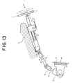
- Fig. 13 shows a steering mechanism of a common automobile.
- the parts designated by a and b in this drawing are telescopic shafts.
- the telescopic shaft a is formed by spline fitting a male shaft and a female shaft.
- the telescopic shaft a of this type is required to have the properties of absorbing axial displacement that occurs while the automobile is running and preventing transmission of the displacement and vibration to the steering wheel. Such properties are generally required in the case that the vehicle body has a sub-frame structure and the portion c on which the upper portion of the steering mechanism is secured and the frame e on which the steering rack d is secured are constructed as separate members that are steadily joined by an elastic member f such as a rubber.
- the telescopic function is required in order for an assembling engineer in charge of joining a steering shaft joint g to a pinion shaft h, to fit and secure the telescopic shaft to the pinion shaft after retracting it.
- the telescopic shaft b provided in the upper portion of the steering mechanism also has a male shaft and female shaft spline connected.
- the telescopic shaft b is required to be extended and retracted in the axial direction in order for the driver to change and adjust the position of the steering wheel i in the axial direction to achieve the optimum position for driving the automobile.
- EP1078843A1 teaches to fit multiple sets of torque transmission members (column-like members) in multiple sets of axial grooves formed on the outer circumferential surface of the male shaft and the inner circumferential surface of the female shaft.
- Each set of the torque transmission members include a plurality of needle rollers arranged along the axial direction.
- the male shaft and the female shaft can be slid in the axial direction with a stable slide load without play.
- the male shaft and the female shaft can transmit the torque with high rigidity while eliminating play in the rotational direction.
- adjusting members made of a resin, which is adapted to absorb the clearance (or play) between the needle rollers.
- EP1078843A1 teaches to absorb the clearance between the plurality of needle rollers by means of adjusting members provided between the needle rollers arranged along the axial direction, clearance sometimes remains between the needle rollers, which may cause a knocking sound.
- the present invention has been made in view of the above-described circumstances, and an object of the present invention is to provide a telescopic shaft used for steering of a vehicle that can realize a stable slide load and prevent play in the rotational direction reliably to enable torque transmission with high rigidity while preventing generation of noises.
- a telescopic shaft used for steering of a vehicle in which a male shaft and a female shaft are fitted to each other non-rotatably and slidably, wherein at least one set of torque transmission members are disposed in at least one set of intermediate fitting portions formed on the outer circumferential surface of said male shaft and the inner circumferential surface of said female shaft, and a stopper plate for regulating movement of said at least one set of torque transmission members with respect to the axial direction is provided at an end portion of said male shaft or in the vicinity thereof.
- the torque transmission members it is possible to secure the torque transmission members with a moderate preload without clearance in the axial direction.
- the torque transmission members are not moved in the axial direction when the male shaft and the female shaft slide relative to each other, and it is possible to prevent unpleasant knocking sounds form being generated.
- said at least one set of intermediate fitting portions be composed of at least one pair of axial grooves formed on the outer circumferential surface of said male shaft and the inner circumferential surface of said female shaft respectively, and the axial grooves of said male shaft have a surface that is substantially perpendicular to the axial direction and in contact with said at least one set of torque transmission members.
- this preferable structure thanks to the provision of the surface that is oriented substantially perpendicularly to the axial direction and in contact with the torque transmission members, it is possible to regulate movement of the torque transmission members with respect to the axial direction by means of this surface perpendicular to the axial direction without providing an additional member. Accordingly, it is possible to reduce the number of the parts to realize a reduction in the manufacturing cost. In addition, since no additional member is used, reduction in the weight and size is made possible.
- said stopper plate be composed of an elastic member for applying axial preload and a pair of flat plates that hold the elastic member therebetween. According to this preferable structure, thanks to the stopper plate composed of an elastic member for applying axial preload and the pair of flat plates that hold the elastic member therebetween, it is possible to prevent axial movement of the torque transmission members by applying a moderate preload to the torque transmission member to positively preventing unpleasant knocking sounds from being generated.
- said stopper plate be fixed to a small diameter portion formed at an end portion of said male shaft.
- the stopper plate will not drop and it can be securely fixed since the stopper plate is fixed to the small diameter portion formed at an end portion of the male shaft.
- said stopper plate be composed of a flat plate and fixing means for fixing the flat plate at a desired position with respect to the axial direction on said male shaft.
- said stopper plate is composed of a flat plate and fixing means for fixing the flat plate at a desired position with respect to the axial direction on the male shaft.
- Fig. 1 is a longitudinal cross sectional view showing a telescopic shaft used for steering of a vehicle according to the first embodiment of the present invention.
- Fig. 2 is a transverse cross sectional view taken along line X-X in Fig. 1.
- the telescopic shaft used for steering of a vehicle (which will be referred to as the telescopic shaft hereinafter) is composed of a male shaft 1 and a female shaft 2 that are fitted to each other non-rotatably and slidably.
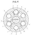
- three axially extending grooves 3 arranged at regular intervals of 120 degrees along the circumferential direction are formed.
- three axially extending grooves 4 having a substantially circular arc shape arranged circumferentially between the three axial grooves 3 at regular intervals of 120 degrees along the circumferential direction are formed.
- three axially extending grooves 5 having a circular arc shape are provided at regular intervals of 120 degrees along the circumferential direction.
- three axially extending grooves 6 having a substantially circular arc shape arranged circumferentially between the three axial grooves 5 at regular intervals of 120 degrees along the circumferential direction are formed.
- the axial grooves 3 and 5 constitute three first intermediate fitting portions for three sets of spherical members 7 that will be described later, and the axial grooves 4 and 6 constitute three second intermediate fitting portions for three sets of cylindrical members 8 that will be described later.
- These three pairs of axial grooves 3 and 5 (or the first intermediate fitting portions) and the three pairs of axial grooves 4 and 6 (or the second intermediate fitting portions) are alternately arranged along the circumferential direction at regular intervals of 60 degrees.
- a first torque transmission apparatus is constructed by rotatably providing three sets of first torque transmission members (spherical members) 7 between the three axial grooves 3 of the male shaft 1 and the three axial grooves 5 of the female shaft 2 with three corrugated elastic members (or leaf springs) 9 for applying preload therebetween.
- the first torque transmission members 7 are adapted to roll when the male shaft 1 and the female shaft 2 move in the axial direction relative to each other, and upon rotation of these shafts, to transmit a torque while constrained by the leaf springs 9.
- a second torque transmission apparatus is constructed by slidably providing three sets of second torque transmission members (or cylindrical members) 8 between the three axial grooves 4 of the male shaft 1 and the three axial grooves 6 of the female shaft 2 respectively.
- the second torque transmission members 8 allow axial movement of the male shaft 1 and the female shaft 2 relative to each other, and upon rotation of these shafts, transmit a torque.
- the leaf springs 9 are adapted to preload the spherical members 7 and the cylindrical members 8 against the female shaft 2 to eliminate play when the torque is not transmitted, and to deform elastically to constrain the spherical members 7 in the circumferential direction between the male shaft 1 and the female shaft 2 when the torque is transmitted.
- the spherical members 7 and the cylindrical members 8 are preloaded by the leaf springs 9 against the female shaft 2 without play, when the torque is not transmitted, play between the male shaft 1 and the female shaft 2 can be eliminated reliably, and when the male shaft 1 and the female shaft 2 relatively move in the axial direction, the male shaft 1 and the female shaft 2 can slide in the axial direction with a steady sliding load without play.
- a sliding surface functions only as a sliding surface as with the case with the conventional art, the preload for preventing play is required to be restricted to a certain load. This is because the sliding load is determined as the product of the friction coefficient and the preload, and if the preload is increased with a view to eliminate play or to improve the rigidity of the telescopic shaft, the sliding load is increased to create vicious circle.
- a rolling mechanism is partly used, and it is possible to increase the preload without a significant increase in the sliding load. Accordingly, improvement in the elimination of play and improvement in the rigidity, which could not be realized in the conventional art, can be achieved without an increase in the sliding load.
- the three sets of leaf springs 9 elastically deform to constrain the three sets of spherical members 7 with respect to the circumferential direction between the male shaft 1 and the female shaft 2.
- the three sets of cylindrical members 8 set between the male shaft 1 and the female shaft 2 function to transmit the most part of the torque.
- the spherical members 7 may be balls.
- the cylindrical members 8 may be needle rollers.
- the needle roller 8 is advantageous since it receives the load through line contact and the contact pressure can be made low as compared to the ball 7, which receives the load through point contact. Therefore, the use of the needle rollers is advantageous over the case in which all the rows are constructed as ball rolling structures in the following respects:
- the needle rollers 8 function as keys for transmitting torque between the male shaft 1 and the female shaft 2, and in addition, they are in sliding contact with the inner circumferential surface of the female shaft 2. Advantages of this structure over the conventional spline connection are as follows:
- the partial use of the balls is advantageous in the following respect as compared to the structure in which all the rows are composed of needle rollers and the all the rows are adapted to slide:
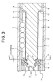
- Fig. 3 is an enlarged longitudinal cross sectional view showing the principal portion of Fig. 1.
- Fig. 4 is an enlarged transverse cross sectional view taken along line Y-Y in Fig. 3.
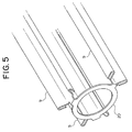
- Fig. 5 is a perspective view showing the elastic members (leaf springs) connected by a connecting portion.
- Fig. 6 is an enlarged view as seen from the direction indicated by arrow A in Fig. 3.
- a small diameter portion 1a is formed at an end portion of the male shaft 1.
- a stopper plate 10 for regulating axial movement of the needle rollers 8 is provided on the small diameter portion 1a.
- the stopper plate 10 is composed of an elastic member 11 for applying axial preload and a pair of flat plates 12 and 13 between which the elastic member 11 for applying axial preload is held.
- the flat plate 13 the elastic member 11 for applying axial preload and the flat plate 13 are fitted on the small diameter portion 1a in the mentioned order, and then the end portion 1b of the small diameter portion 1a is clinched or plastically deformed so as to be firmly secured to the small diameter portion 1a.
- the stopper plate 10 is adapted to preload the needle rollers 8 in the axial direction to prevent axial movement of the needle rollers 8 by means of the elastic member 11 for applying axial preload while the flat plate 13 is in contact with the needle rollers 8.
- the stroke of the telescopic shaft can be determined by the stopper plate 10. This is because when the balls roll to impinge the stopper plate, the balls cannot roll any more.
- the elastic member 11 for applying axial preload is made of a rubber, a resin or a steel leaf spring.
- the elastic member 11 for applying axial preload and the flat plates 12 and 13 may be constructed as separate members, but it is preferable that they are constructed as an integrally formed member in view of facility of assembling.
- the elastic member 11 for applying axial preload is made of a rubber
- it can be made integral by applying vulcanization on the flat plates 12 and 13.
- a product that is easy to assemble can be made at low cost.
- the elastic member 11 for applying axial preload is made of a resin
- it can be made integral by molding a corrugated part integrally with the flat plates 12 and 13. In this case, the advantages same as above can be realized.
- the flat plates 12 and 13 may be steel plates, resin plates, or steel plates covered with a resin coating.
- the axial grooves 3, 4 of the male shaft 1 have surfaces 14 and 15 that are substantially perpendicular to the axial direction and in contact with the balls 7 and needle rollers 8.
- axial movement of the needle rollers 8 is regulated by the stopper plate 10 provided on the small diameter portion 1a of the male shaft 1 at one end thereof, and the other side of the needle rollers 8 abuts the surface 15 which is perpendicular to the axial direction so that axial movement thereof is regulated.
- the flat plate 13 of the stopper plate 10 is in contact with the needle rollers 8, and the elastic member 11 preloads the needle rollers 8 appropriately so that the needle rollers 8 will not move in the axial direction.
- the needle rollers 8 are not moved in the axial direction when the male shaft 1 and the female shaft 3 slide relative to each other, and it is possible to positively prevent unpleasant knocking sounds from being generated.
- the axial grooves 3, 4 of the male shaft 1 have the surfaces 14 and 15 that are substantially perpendicular to the axial direction and in contact with the balls 7 and needle rollers 8, it is possible to regulate the axial movement of the balls 7 and the needle rollers 8 by the surface 15 without providing an additional member. Accordingly, it is possible to reduce the number of the parts to reduce the manufacturing cost. In addition, weight reduction and size reduction can be made possible since additional members are not used.
- the three leaf springs 9 for preloading the three sets of balls 7 are connected by a ring-like connecting portion 20 as shown in Figs. 3 to 5.
- the small diameter portion 1a at the end portion of the male shaft 1 has an annular surface 21 formed at its stepped portion.
- the ring-like connecting portion 20 is fitted on the small diameter portion 1a and disposed along the stepped annular surface 21.
- the annular surface 21 at the stepped portion may be of any shape, though it should be an annular surface facing the axial direction of the male shaft 1.
- the ring-like connecting portion 20 is connected with the axial end portions of the three leaf springs 9 at three positions on the circumferential edge thereof. As shown in Fig. 5, the ring-like connecting portion 20 is constructed integrally with the three leaf springs 9 that extend along the axial direction.
- the three leaf springs 9 serving as rolling base surfaces can be made integral to reduce the virtual number of the parts from three to one, while adopting the structure in which the balls 7 and needle rollers 8 are used in combination.
- the small diameter portion 1a formed at the end portion of the male shaft 1 passes through the ring-like connecting portion 20. Accordingly, when the three leaf springs 9 are assembled, the small diameter portion 1a at the end portion of the male shaft 1 is inserted through the ring-like connecting portion 20 to function as a guide for the assembling operation. Thus, the assembling operation can be facilitated, and the manufacturing cost can be reduced by a decrease in the time required for the assembling.
- the ring-like connecting portion 20 is disposed in the clearance with respect to the axial direction between the flat plate 13 of the stopper plate 10 and the annular surface 21 at the stepped portion 21.
- This axial clearance is, for example, about 0.3 to 2.0mm.
- the ring-like connecting portion 20 does not constrain movement of the three leaf springs 9 even when the leaf springs 9 are deformed by a torque input.
- each leaf spring 9 in cross section, is so shaped to be linearly extended substantially in parallel to the axial grooves 3 of the male shaft 1, and the flat portion at the central portion of each leaf spring 9 is joined to the circumferential edge portion of the ring-like connecting portion 20. Both end portions of each leaf spring 9 are folded outwardly from the center side.
- the small diameter portion 1a formed at the end portion of the male shaft 1 is adapted to pass through the ring-like connecting portion 20.
- a clearance in the radial direction is formed between the small diameter portion 1a of the male shaft 1 and the ring-like connecting portion 20.
- the radial clearance is, for example, 0.2 to 1.0mm.
- the ring-like connecting portion 20 does not constrain movement of the three leaf springs 9 thanks to the presence of the radial clearance even when the leaf springs 9 are deformed by a torque input.
- Fig. 7 is a longitudinal cross sectional view showing a telescopic shaft used for steering of a vehicle according to the second embodiment of the present invention.
- Fig. 8 is an enlarged view as seen from the direction indicated by arrow A in Fig. 7.
- a circumferential groove 31 is formed on the small diameter portion 1a of the male shaft 1.
- a retaining ring 32 is fitted in the circumferential groove 31.
- FIG. 9 is a longitudinal cross sectional view showing a telescopic shaft used for steering of a vehicle according to the third embodiment of the present invention.
- Fig. 10 is an enlarged view as seen from the direction indicated by arrow A in Fig. 9.
- a screw hole 33 extending in the axial direction is formed on the small diameter portion 1a of the male shaft 1.
- a bolt 34 is screwed into the screw hole 33, through the stopper plate 10 (more specifically, the flat plate 12) and tightened.
- the stopper plate 10 is fixed with respect to the axial direction.
- Fig. 11 is a longitudinal cross sectional view showing a telescopic shaft used for steering of a vehicle according to the fourth embodiment of the present invention.
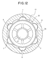
- Fig. 12 is an enlarged view as seen from the direction indicated by arrow A in Fig. 11.
- the stopper plate 10 is composed of a flat plate 35 and a push nut 36 (i.e. the fixing means) for fixing the flat plate 35 at a desired position with respect to the axial direction of the male shaft 1.
- the push nut 36 fixing means
- the flat plate 35 is intermediately set, and the push nut 36 is pressed against it from the axial direction and fixed so that undesirable clearance will be eliminated.
- the needle rollers 8 are not moved in the axial direction when the male shaft 1 and the female shaft 3 slide relative to each other, and it is possible to prevent unpleasant knocking sounds from being generated.
- the structures and operations other than the above are the same as those in the above-described embodiment.
Landscapes
- Engineering & Computer Science (AREA)
- General Engineering & Computer Science (AREA)
- Mechanical Engineering (AREA)
- Ocean & Marine Engineering (AREA)
- Chemical & Material Sciences (AREA)
- Combustion & Propulsion (AREA)
- Transportation (AREA)
- Steering Controls (AREA)
- Shafts, Cranks, Connecting Bars, And Related Bearings (AREA)
- Transmission Devices (AREA)
Abstract
Description
- Damping effects at the sliding portion is high as compared to the ball rolling structure, and therefore vibration absorption performance is high.
- In transmitting the same torque, the contact pressure can be made lower in the case of the needle roller, and therefore the axial length can be made shorter, so that the space can be used efficiently.
- In transmitting the same torque, the contact pressure can be made lower in the case of the needle roller, and therefore, an additional process for hardening the surface of the axial grooves on the female shaft by heat processing etc. is not required.
- It is possible to reduce the number of the parts.
- It is possible to improve the facility of assembling.
- It is possible to reduce the assembling cost.
- The needle rollers are mass-produced parts and available at a very low cost.
- Since the needle rollers have been ground after heat processing, their surface hardness is high and they have high durability against wear.
- Since the needle rollers have been ground, their surface is fine and the friction coefficient in sliding is low, and therefore, the sliding load can be made low.
- Since the length and the setting position of the needle rollers can be changed in accordance with use conditions, they can be adapted to various applications without changing the design concept.
- Even in the case that it is required to further reduce the friction coefficient in sliding depending on use conditions, which sometimes occurs, the sliding characteristics can be changed only by applying a surface processing on the needle rollers, namely, the needle rollers can be adapted to various applications without changing the design concept.
- Since it is possible to manufacture needle rollers having different diameters in orders of several microns at low cost, it is possible to restrict the clearance between the male shaft, the needle rollers and the female shaft to the minimum, and therefore it is easy to enhance the rigidity in the twisting direction of the shaft.
- Since the frictional resistance is low, the sliding load can be made low.
- The preload can be made high, and it is possible to achieve both high rigidity and elimination of play for a long time.
Claims (5)
- A telescopic shaft used for steering of a vehicle in which a male shaft and a female shaft are fitted to each other non-rotatably and slidably, wherein at least one set of torque transmission members are disposed in at least one set of intermediate fitting portions formed on the outer circumferential surface of said male shaft and the inner circumferential surface of said female shaft, and a stopper plate for regulating movement of said at least one set of torque transmission members with respect to the axial direction is provided at an end portion of said male shaft or in the vicinity thereof.
- A telescopic shaft used for steering of a vehicle according to claim 1, wherein said at least one set of intermediate fitting portions comprise at least one set of axial grooves formed on the outer circumferential surface of said male shaft and the inner circumferential surface of said female shaft respectively, and the axial grooves of said male shaft have a surface that is substantially perpendicular to the axial direction and in contact with said at least one set of torque transmission members.
- A telescopic shaft used for steering of a vehicle according to claim 1 or 2, wherein said stopper plate comprises an elastic member for applying axial preload and a pair of flat plates that hold the elastic member therebetween.
- A telescopic shaft used for steering of a vehicle according to claim 1 or 2, wherein said stopper plate is fixed to a small diameter portion formed at an end portion of said male shaft.
- A telescopic shaft used for steering of a vehicle according to claim 1 or 2, wherein said stopper plate comprises a flat plate and fixing means for fixing the flat plate at a desired position with respect to the axial direction on said male shaft.
Applications Claiming Priority (3)
| Application Number | Priority Date | Filing Date | Title |
|---|---|---|---|
| JP2002289965 | 2002-10-02 | ||
| JP2002289965A JP4196630B2 (en) | 2002-10-02 | 2002-10-02 | Telescopic shaft for vehicle steering |
| PCT/JP2003/011892 WO2004031021A1 (en) | 2002-10-02 | 2003-09-18 | Extendable shaft for vehicle steering |
Publications (3)
| Publication Number | Publication Date |
|---|---|
| EP1568569A1 true EP1568569A1 (en) | 2005-08-31 |
| EP1568569A4 EP1568569A4 (en) | 2006-11-29 |
| EP1568569B1 EP1568569B1 (en) | 2009-05-06 |
Family
ID=32063756
Family Applications (1)
| Application Number | Title | Priority Date | Filing Date |
|---|---|---|---|
| EP03799110A Expired - Lifetime EP1568569B1 (en) | 2002-10-02 | 2003-09-18 | Extendable shaft for vehicle steering |
Country Status (7)
| Country | Link |
|---|---|
| US (1) | US7559267B2 (en) |
| EP (1) | EP1568569B1 (en) |
| JP (1) | JP4196630B2 (en) |
| CN (1) | CN1688471A (en) |
| AU (1) | AU2003264486A1 (en) |
| DE (1) | DE60327548D1 (en) |
| WO (1) | WO2004031021A1 (en) |
Cited By (10)
| Publication number | Priority date | Publication date | Assignee | Title |
|---|---|---|---|---|
| WO2004033270A1 (en) | 2002-10-10 | 2004-04-22 | Nsk Ltd. | Extendable vehicle steering shaft |
| DE102006058999A1 (en) * | 2006-12-14 | 2008-06-19 | Bayerische Motoren Werke Ag | Torque transfer device comprises coaxial inner and outer tubes with longitudinal grooves which form seatings for at least two rows of ball bearings, wire cushion pads being positioned between bearings and outer tube |
| US7404768B2 (en) | 2003-07-02 | 2008-07-29 | Nsk Ltd. | Telescopic shaft for motor vehicle steering |
| US7416199B2 (en) | 2003-02-06 | 2008-08-26 | Nsk Ltd. | Steering device for motor vehicle |
| US7416216B2 (en) | 2002-11-29 | 2008-08-26 | Nsk Ltd. | Telescopic shaft for vehicle steering |
| US7429060B2 (en) | 2002-06-11 | 2008-09-30 | Nsk Ltd. | Telescopic shaft for steering of vehicle, and telescopic shaft for steering of vehicle with cardan shaft joint |
| US7481130B2 (en) | 2001-10-01 | 2009-01-27 | Nsk Ltd. | Vehicle steering telescopic shaft |
| US7559267B2 (en) | 2002-10-02 | 2009-07-14 | Nsk Ltd. | Extendable shaft for vehicle steering |
| US8157659B2 (en) | 2005-09-30 | 2012-04-17 | Jtekt Corporation | Telescopic shaft and vehicle steering apparatus |
| EP1557338B1 (en) * | 2002-10-24 | 2014-05-28 | NSK Ltd. | Extensible shaft for steering of vehicle |
Families Citing this family (21)
| Publication number | Priority date | Publication date | Assignee | Title |
|---|---|---|---|---|
| US20070157754A1 (en) * | 2004-01-27 | 2007-07-12 | Nsk Ltd. | Telescopic shaft for vehicle steering |
| JP2005313691A (en) * | 2004-04-27 | 2005-11-10 | Nsk Ltd | Telescopic shaft for vehicle steering |
| WO2006009230A1 (en) * | 2004-07-21 | 2006-01-26 | Nsk Ltd. | Telescopic shaft for vehicle steering |
| JP4770193B2 (en) * | 2005-02-16 | 2011-09-14 | 日本精工株式会社 | Telescopic shaft for vehicle steering |
| JP4586983B2 (en) * | 2005-06-29 | 2010-11-24 | 日本精工株式会社 | Telescopic shaft for vehicle steering |
| EP2174030B1 (en) * | 2007-07-26 | 2013-09-11 | Shaft-Form-Engineering GmbH | Rolling-sliding unit and cardan shaft having the same |
| DE102008041155A1 (en) * | 2008-08-11 | 2010-02-18 | Zf Lenksysteme Gmbh | Outer tube of a steering shaft in a motor vehicle |
| US8485057B1 (en) * | 2011-05-18 | 2013-07-16 | Horizon, Llc | Push-pull control utilizing linear and rotational input |
| SE536274C2 (en) * | 2011-10-03 | 2013-07-30 | Atlas Copco Ind Tech Ab | Screw-driven press unit |
| CN102661327A (en) * | 2012-05-12 | 2012-09-12 | 吉林大学 | Telescopic rolling ball spline type crossed shaft universal transmission device |
| US9157482B2 (en) * | 2013-10-11 | 2015-10-13 | Steering Solutions Ip Holding Corporation | Shaft assembly with anti-pull apart stake |
| BE1022076B1 (en) * | 2014-01-29 | 2016-02-15 | Cockerill Maintenance & Ingenierie Sa | IMPACT MITIGATION DEVICE |
| DE102016218830A1 (en) * | 2016-09-29 | 2018-03-29 | Aktiebolaget Skf | unit |
| US10641315B2 (en) * | 2017-04-04 | 2020-05-05 | Steering Solutions Ip Holding Corporation | Steering shaft assembly having anti-pull apart feature |
| DE102017221075B4 (en) * | 2017-11-24 | 2019-06-27 | Thyssenkrupp Ag | Steering shaft for a motor vehicle |
| CN108457982A (en) * | 2018-04-16 | 2018-08-28 | 盐城工学院 | Track-type facilities |
| CN109538646A (en) * | 2019-01-04 | 2019-03-29 | 中国船舶重工集团公司第七0三研究所 | A kind of diaphragm type large compensation shaft coupling |
| KR102890056B1 (en) * | 2019-03-14 | 2025-11-25 | 에이치엘만도 주식회사 | Steering Column for Vehicle |
| CN109751193B (en) * | 2019-03-28 | 2022-09-27 | 新疆金风科技股份有限公司 | Wind generating set |
| CN110371177B (en) * | 2019-06-11 | 2020-07-28 | 潍柴动力股份有限公司 | Steering transmission shaft |
| CN112503107B (en) * | 2020-11-27 | 2022-10-04 | 湖北多力多传动轴有限公司 | Overload elastic protection coupling |
Family Cites Families (81)
| Publication number | Priority date | Publication date | Assignee | Title |
|---|---|---|---|---|
| US2607257A (en) | 1950-08-30 | 1952-08-19 | Minshall Estey Organ Inc | Organ key loading device |
| US3169407A (en) | 1962-02-28 | 1965-02-16 | Westinghouse Air Brake Co | Motion converting device |
| US3279218A (en) * | 1964-05-11 | 1966-10-18 | Rockwell Standard Co | Extensible drive connections |
| JPS4519207Y1 (en) | 1965-01-02 | 1970-08-05 | ||
| US3356424A (en) | 1965-04-30 | 1967-12-05 | Gen Motors Corp | Ball spline assembly |
| US3392599A (en) | 1966-12-30 | 1968-07-16 | Gen Motors Corp | Energy absorbing device |
| US3444753A (en) | 1967-12-14 | 1969-05-20 | Bendix Corp | No-lash axially movable steering column |
| US3604285A (en) | 1970-04-06 | 1971-09-14 | Saab Scania Ab | Energy-absorbing device and method of making the same |
| CH553350A (en) | 1972-06-20 | 1974-08-30 | Betrix Claude | DEVICE FOR GUIDING THE AXIAL DISPLACEMENT OF A CYLINDRICAL ORGAN. |
| DE2461289B1 (en) | 1974-12-23 | 1975-11-13 | Loehr & Bromkamp Gmbh | Constant velocity swivel |
| DE2804778C3 (en) | 1978-02-04 | 1982-04-08 | Uni-Cardan Ag, 5200 Siegburg | Telescopic drive shaft |
| US4384861A (en) | 1979-10-10 | 1983-05-24 | Firma LWM Lemforder Gelenkwellen GmbH | Universal joint shaft, particularly for a steering column of motor vehicles |
| US4357137A (en) | 1980-08-18 | 1982-11-02 | Arinc Research Corporation | Shaft coupling |
| US4500141A (en) | 1982-09-13 | 1985-02-19 | Daugherty Estes M | Drill steel idler guide |
| US4509386A (en) | 1982-11-15 | 1985-04-09 | General Motors Corporation | Lash-free telescopic steering shaft assembly and method of making the assembly |
| SE450153B (en) | 1985-01-22 | 1987-06-09 | Ffv Affersverket | TELESCOPE CONTROL, SPECIAL FOR TRANSMISSION OF TORQUE |
| GB8513070D0 (en) | 1985-05-23 | 1985-06-26 | Brd Co Ltd | Sliding splined joint |
| AT384405B (en) | 1985-07-22 | 1987-11-10 | Supervis Ets | LENGTH-CHANGEABLE STEERING SPINDLE FOR STEERING DEVICES IN MOTOR VEHICLES |
| JPS62244758A (en) | 1986-04-18 | 1987-10-26 | Koyo Seiko Co Ltd | Position adjusting device for steering handle |
| JPH01145670A (en) | 1987-12-01 | 1989-06-07 | Minolta Camera Co Ltd | Compound device |
| SE461605B (en) | 1987-03-12 | 1990-03-05 | Ffv Autotech Ab | Torque transmitting telescopic shaft with overload protection |
| DE3730393C2 (en) | 1987-09-10 | 1994-01-13 | Lemfoerder Metallwaren Ag | Steering shaft for motor vehicles, consisting of axially displaceable shaft parts |
| US5184978A (en) | 1990-04-16 | 1993-02-09 | Gkn Automotive, Inc. | Telescopic triplan universal joint |
| JPH04123775A (en) | 1990-09-14 | 1992-04-23 | Sony Corp | Connector device |
| FR2669693A1 (en) | 1990-11-23 | 1992-05-29 | Nacam | EXTENDABLE COUPLING PERFECTED TO SOLIDARIZE IN ROTATION TWO TREES WITH INTEGRATED SECURITY SYSTEM AND ITS APPLICATION IN PARTICULAR TO DIRECTIONS OF AUTOMOBILES. |
| US5235734A (en) | 1991-11-04 | 1993-08-17 | Itt Corporation | Collapsible steering shaft apparatus and method of making same |
| US5460574A (en) | 1993-08-31 | 1995-10-24 | Trw Inc. | Variable length shaft assembly with a lash bushing |
| US5542343A (en) | 1995-09-26 | 1996-08-06 | Trw Inc. | Power steering assembly with damping ring |
| DE19538303A1 (en) | 1995-10-14 | 1997-04-17 | Zahnradfabrik Friedrichshafen | Steering column of a motor vehicle |
| JP3671571B2 (en) | 1996-02-29 | 2005-07-13 | 株式会社デンソー | Power transmission device |
| US5709605A (en) | 1996-12-23 | 1998-01-20 | General Motors Corporation | Shaft coupling |
| FR2759436B1 (en) | 1997-02-11 | 1999-04-30 | Pierre Guimbretiere | HOMOCINETIC SLIDING JOINT WITH TRIPOD |
| DE19735443A1 (en) | 1997-08-16 | 1999-02-18 | Schaeffler Waelzlager Ohg | Torque-transmitting shaft for profiled pipe |
| DE19801166C2 (en) | 1998-01-15 | 2001-06-28 | Micro Compact Car Smart Gmbh | Motor vehicle steering shaft with two shaft sections |
| DE19820291B4 (en) * | 1998-05-07 | 2006-06-14 | Willi Elbe Gelenkwellen Gmbh & Co. Kg | Multiple telescopic steering shaft with blocking device |
| DE19824477A1 (en) | 1998-05-30 | 1999-12-02 | Daimler Chrysler Ag | Telescopic steering shaft for vehicle |
| JP3659033B2 (en) | 1998-11-24 | 2005-06-15 | 日本精工株式会社 | Shock absorbing electric power steering system |
| JP2000205288A (en) | 1999-01-12 | 2000-07-25 | Koyo Seiko Co Ltd | Drive shaft |
| DE19905350A1 (en) | 1999-02-10 | 2000-08-24 | Daimler Chrysler Ag | Combined sliding piece with vibration isolation |
| ES2161127B1 (en) | 1999-03-16 | 2002-09-01 | Castellon Melchor Daumal | TELESCOPIC TREE FOR STEERING COLUMNS IN CAR VEHICLES WITH SLIDING SYSTEM WITH LOAD CONTROL. |
| JP2000337395A (en) | 1999-05-27 | 2000-12-05 | Koyo Seiko Co Ltd | Propeller shaft with ball spline mechanism |
| FR2795785B1 (en) | 1999-06-30 | 2002-06-28 | Nacam | BALL COUPLING DEVICE FOR TWO SLIDING SHAFTS |
| FR2795787B1 (en) | 1999-06-30 | 2003-05-23 | Nacam | BALL COUPLING DEVICE FOR TWO SLIDING SHAFTS |
| DE59900183D1 (en) | 1999-12-10 | 2001-09-06 | Skf Linearsysteme Gmbh | Rolling bearings for longitudinal movements |
| US6279953B1 (en) | 1999-12-22 | 2001-08-28 | Trw Inc. | Flexible mount for an intermediate steering column |
| JP2001239944A (en) | 2000-03-01 | 2001-09-04 | Nsk Ltd | Connecting structure of telescopic shaft |
| US6364778B1 (en) | 2000-05-25 | 2002-04-02 | Spicer Driveshaft, Inc. | Axially adjustable steering shaft assembly with ball spline |
| JP3694637B2 (en) | 2000-06-27 | 2005-09-14 | 光洋精工株式会社 | Ball spline joint and intermediate shaft of steering device |
| FR2811041B1 (en) | 2000-06-28 | 2002-10-11 | Nadella | BALL SLIDE MODULE AND CORRESPONDING ASSEMBLY |
| JP2002046633A (en) | 2000-08-07 | 2002-02-12 | Nsk Ltd | Electric power steering device |
| US6582313B2 (en) | 2000-12-22 | 2003-06-24 | Delphi Technologies, Inc. | Constant velocity stroking joint having recirculating spline balls |
| US6505969B2 (en) | 2001-01-31 | 2003-01-14 | The Torrington Company | Interlocking linear roller bearing |
| US6533459B2 (en) | 2001-01-31 | 2003-03-18 | The Torrington Company | Adjustable, self-aligning, linear roller bearing |
| DE10106982A1 (en) | 2001-02-15 | 2002-08-29 | Ina Schaeffler Kg | linear guide |
| US6533666B2 (en) | 2001-04-03 | 2003-03-18 | Delphi Technologies, Inc. | Intermediate steering shaft for motor vehicle |
| DE10123413B4 (en) | 2001-05-14 | 2006-03-16 | Gkn Driveline Deutschland Gmbh | drive shaft |
| JP4571341B2 (en) | 2001-06-18 | 2010-10-27 | 水島プレス工業株式会社 | Damper mechanism of steering device |
| DE10297302B4 (en) | 2001-10-01 | 2012-07-12 | Nsk Ltd. | Telescopic shaft for a vehicle steering |
| FR2830912B1 (en) | 2001-10-15 | 2003-12-19 | Nacam | DEVICE FOR COUPLING ROTATION OF TWO TELESCOPIC SHAFTS |
| US6620050B2 (en) | 2001-10-30 | 2003-09-16 | Mando Corporation | Universal joint |
| US7226360B2 (en) | 2001-12-14 | 2007-06-05 | Gkn Driveline North America, Inc. | Grease cap for a constant velocity joint |
| US6761503B2 (en) | 2002-04-24 | 2004-07-13 | Torque-Traction Technologies, Inc. | Splined member for use in a slip joint and method of manufacturing the same |
| US6729648B2 (en) | 2002-06-07 | 2004-05-04 | Sealy Technology Llc | Non-linear energy absorbing column assembly |
| JP4258470B2 (en) | 2002-06-11 | 2009-04-30 | 日本精工株式会社 | Telescopic shaft for vehicle steering and telescopic shaft for vehicle steering with cardan shaft joint |
| US6893353B2 (en) | 2002-06-18 | 2005-05-17 | Torque-Traction Technologies, Inc. | Rolling ball spline slip joint formed from two tubular members |
| DE20212294U1 (en) | 2002-06-18 | 2003-10-30 | DURA Automotive Systems Reiche GmbH & Co. KG, 32791 Lage | Telescopic safety steering column for road vehicle has outer tube with three flattened faces containing groups of three barrel-shaped rollers engaging three concave sides of inner tube |
| DE50302563D1 (en) | 2002-06-18 | 2006-05-04 | Dura Automotive Systems Reiche | Steering shaft for motor vehicles |
| DE10233758B4 (en) | 2002-07-25 | 2004-07-29 | Gkn Driveline Deutschland Gmbh | Longitudinal displacement unit with brake rollers |
| JP3797304B2 (en) | 2002-09-13 | 2006-07-19 | 日本精工株式会社 | Telescopic shaft for vehicle steering |
| JP4196630B2 (en) | 2002-10-02 | 2008-12-17 | 日本精工株式会社 | Telescopic shaft for vehicle steering |
| JP4254194B2 (en) | 2002-10-10 | 2009-04-15 | 日本精工株式会社 | Telescopic shaft for vehicle steering |
| JP4196642B2 (en) | 2002-10-24 | 2008-12-17 | 日本精工株式会社 | Telescopic shaft for vehicle steering |
| JP4419841B2 (en) | 2002-11-29 | 2010-02-24 | 日本精工株式会社 | Telescopic shaft for vehicle steering |
| JP2004196261A (en) | 2002-12-20 | 2004-07-15 | Nsk Ltd | Telescopic shaft for vehicle steering |
| JPWO2004062981A1 (en) | 2003-01-10 | 2006-05-18 | 日本精工株式会社 | Telescopic shaft for vehicle steering |
| JP4190905B2 (en) | 2003-02-06 | 2008-12-03 | 日本精工株式会社 | Vehicle steering device |
| US7404768B2 (en) | 2003-07-02 | 2008-07-29 | Nsk Ltd. | Telescopic shaft for motor vehicle steering |
| US20050070365A1 (en) | 2003-09-30 | 2005-03-31 | Riefe Richard K. | Bushing for telescoping steering column assembly |
| US20070157754A1 (en) | 2004-01-27 | 2007-07-12 | Nsk Ltd. | Telescopic shaft for vehicle steering |
| FR2875279B1 (en) | 2004-09-14 | 2006-11-24 | Nacam France Sas | JOINT HOLDING BALL JOINT DEVICE OF TWO SLIDING TREES |
| JP4770193B2 (en) | 2005-02-16 | 2011-09-14 | 日本精工株式会社 | Telescopic shaft for vehicle steering |
-
2002
- 2002-10-02 JP JP2002289965A patent/JP4196630B2/en not_active Expired - Lifetime
-
2003
- 2003-09-18 EP EP03799110A patent/EP1568569B1/en not_active Expired - Lifetime
- 2003-09-18 WO PCT/JP2003/011892 patent/WO2004031021A1/en not_active Ceased
- 2003-09-18 AU AU2003264486A patent/AU2003264486A1/en not_active Abandoned
- 2003-09-18 US US10/529,750 patent/US7559267B2/en not_active Expired - Lifetime
- 2003-09-18 CN CNA038237636A patent/CN1688471A/en active Pending
- 2003-09-18 DE DE60327548T patent/DE60327548D1/en not_active Expired - Lifetime
Cited By (12)
| Publication number | Priority date | Publication date | Assignee | Title |
|---|---|---|---|---|
| US7481130B2 (en) | 2001-10-01 | 2009-01-27 | Nsk Ltd. | Vehicle steering telescopic shaft |
| US7429060B2 (en) | 2002-06-11 | 2008-09-30 | Nsk Ltd. | Telescopic shaft for steering of vehicle, and telescopic shaft for steering of vehicle with cardan shaft joint |
| US7559267B2 (en) | 2002-10-02 | 2009-07-14 | Nsk Ltd. | Extendable shaft for vehicle steering |
| WO2004033270A1 (en) | 2002-10-10 | 2004-04-22 | Nsk Ltd. | Extendable vehicle steering shaft |
| EP1553005A4 (en) * | 2002-10-10 | 2007-01-17 | Nsk Ltd | Extendable vehicle steering shaft |
| US7338382B2 (en) | 2002-10-10 | 2008-03-04 | Nsk Ltd. | Extendable vehicle steering shaft |
| EP1557338B1 (en) * | 2002-10-24 | 2014-05-28 | NSK Ltd. | Extensible shaft for steering of vehicle |
| US7416216B2 (en) | 2002-11-29 | 2008-08-26 | Nsk Ltd. | Telescopic shaft for vehicle steering |
| US7416199B2 (en) | 2003-02-06 | 2008-08-26 | Nsk Ltd. | Steering device for motor vehicle |
| US7404768B2 (en) | 2003-07-02 | 2008-07-29 | Nsk Ltd. | Telescopic shaft for motor vehicle steering |
| US8157659B2 (en) | 2005-09-30 | 2012-04-17 | Jtekt Corporation | Telescopic shaft and vehicle steering apparatus |
| DE102006058999A1 (en) * | 2006-12-14 | 2008-06-19 | Bayerische Motoren Werke Ag | Torque transfer device comprises coaxial inner and outer tubes with longitudinal grooves which form seatings for at least two rows of ball bearings, wire cushion pads being positioned between bearings and outer tube |
Also Published As
| Publication number | Publication date |
|---|---|
| CN1688471A (en) | 2005-10-26 |
| DE60327548D1 (en) | 2009-06-18 |
| AU2003264486A1 (en) | 2004-04-23 |
| WO2004031021A1 (en) | 2004-04-15 |
| US20060060022A1 (en) | 2006-03-23 |
| JP4196630B2 (en) | 2008-12-17 |
| EP1568569B1 (en) | 2009-05-06 |
| US7559267B2 (en) | 2009-07-14 |
| EP1568569A4 (en) | 2006-11-29 |
| JP2004122938A (en) | 2004-04-22 |
Similar Documents
| Publication | Publication Date | Title |
|---|---|---|
| US7559267B2 (en) | Extendable shaft for vehicle steering | |
| JP4196642B2 (en) | Telescopic shaft for vehicle steering | |
| EP1553005B1 (en) | Extendable vehicle steering shaft | |
| US7416216B2 (en) | Telescopic shaft for vehicle steering | |
| US7416199B2 (en) | Steering device for motor vehicle | |
| JP4258470B2 (en) | Telescopic shaft for vehicle steering and telescopic shaft for vehicle steering with cardan shaft joint | |
| CN100390000C (en) | Telescopic shaft for vehicle steering | |
| CN100436226C (en) | Telescopic shaft for vehicle steering | |
| WO2004062981A1 (en) | Telescopic shaft for motor vehicle steering | |
| JP3800159B2 (en) | Telescopic shaft for vehicle steering | |
| JP4544252B2 (en) | Telescopic shaft for vehicle steering and telescopic shaft for vehicle steering with cardan shaft joint | |
| JP2005262919A (en) | Telescopic shaft for vehicle steering |
Legal Events
| Date | Code | Title | Description |
|---|---|---|---|
| PUAI | Public reference made under article 153(3) epc to a published international application that has entered the european phase |
Free format text: ORIGINAL CODE: 0009012 |
|
| 17P | Request for examination filed |
Effective date: 20050405 |
|
| AK | Designated contracting states |
Kind code of ref document: A1 Designated state(s): AT BE BG CH CY CZ DE DK EE ES FI FR GB GR HU IE IT LI LU MC NL PT RO SE SI SK TR |
|
| AX | Request for extension of the european patent |
Extension state: AL LT LV MK |
|
| DAX | Request for extension of the european patent (deleted) | ||
| RBV | Designated contracting states (corrected) |
Designated state(s): DE GB |
|
| A4 | Supplementary search report drawn up and despatched |
Effective date: 20061026 |
|
| 17Q | First examination report despatched |
Effective date: 20070724 |
|
| GRAP | Despatch of communication of intention to grant a patent |
Free format text: ORIGINAL CODE: EPIDOSNIGR1 |
|
| GRAS | Grant fee paid |
Free format text: ORIGINAL CODE: EPIDOSNIGR3 |
|
| GRAA | (expected) grant |
Free format text: ORIGINAL CODE: 0009210 |
|
| AK | Designated contracting states |
Kind code of ref document: B1 Designated state(s): DE GB |
|
| REG | Reference to a national code |
Ref country code: GB Ref legal event code: FG4D |
|
| REF | Corresponds to: |
Ref document number: 60327548 Country of ref document: DE Date of ref document: 20090618 Kind code of ref document: P |
|
| PGFP | Annual fee paid to national office [announced via postgrant information from national office to epo] |
Ref country code: GB Payment date: 20090916 Year of fee payment: 7 |
|
| PLBE | No opposition filed within time limit |
Free format text: ORIGINAL CODE: 0009261 |
|
| STAA | Information on the status of an ep patent application or granted ep patent |
Free format text: STATUS: NO OPPOSITION FILED WITHIN TIME LIMIT |
|
| 26N | No opposition filed |
Effective date: 20100209 |
|
| GBPC | Gb: european patent ceased through non-payment of renewal fee |
Effective date: 20100918 |
|
| PG25 | Lapsed in a contracting state [announced via postgrant information from national office to epo] |
Ref country code: GB Free format text: LAPSE BECAUSE OF NON-PAYMENT OF DUE FEES Effective date: 20100918 |
|
| PGFP | Annual fee paid to national office [announced via postgrant information from national office to epo] |
Ref country code: DE Payment date: 20200909 Year of fee payment: 18 |
|
| REG | Reference to a national code |
Ref country code: DE Ref legal event code: R119 Ref document number: 60327548 Country of ref document: DE |
|
| PG25 | Lapsed in a contracting state [announced via postgrant information from national office to epo] |
Ref country code: DE Free format text: LAPSE BECAUSE OF NON-PAYMENT OF DUE FEES Effective date: 20220401 |