EP1568498B1 - Fluid ejection device metal layer layouts - Google Patents
Fluid ejection device metal layer layouts Download PDFInfo
- Publication number
- EP1568498B1 EP1568498B1 EP04019439A EP04019439A EP1568498B1 EP 1568498 B1 EP1568498 B1 EP 1568498B1 EP 04019439 A EP04019439 A EP 04019439A EP 04019439 A EP04019439 A EP 04019439A EP 1568498 B1 EP1568498 B1 EP 1568498B1
- Authority
- EP
- European Patent Office
- Prior art keywords
- portions
- metal layer
- layer
- metal
- conductive
- Prior art date
- Legal status (The legal status is an assumption and is not a legal conclusion. Google has not performed a legal analysis and makes no representation as to the accuracy of the status listed.)
- Expired - Lifetime
Links
- 229910052751 metal Inorganic materials 0.000 title claims description 136
- 239000002184 metal Substances 0.000 title claims description 136
- 239000012530 fluid Substances 0.000 title claims description 31
- 238000010304 firing Methods 0.000 claims description 18
- PCHJSUWPFVWCPO-UHFFFAOYSA-N gold Chemical compound [Au] PCHJSUWPFVWCPO-UHFFFAOYSA-N 0.000 claims description 10
- 239000010931 gold Substances 0.000 claims description 10
- 229910052737 gold Inorganic materials 0.000 claims description 10
- 229910052715 tantalum Inorganic materials 0.000 claims description 8
- GUVRBAGPIYLISA-UHFFFAOYSA-N tantalum atom Chemical compound [Ta] GUVRBAGPIYLISA-UHFFFAOYSA-N 0.000 claims description 8
- 239000000758 substrate Substances 0.000 description 13
- 239000010409 thin film Substances 0.000 description 8
- 230000032798 delamination Effects 0.000 description 7
- 230000004888 barrier function Effects 0.000 description 5
- 238000010586 diagram Methods 0.000 description 5
- 230000008878 coupling Effects 0.000 description 4
- 238000010168 coupling process Methods 0.000 description 4
- 238000005859 coupling reaction Methods 0.000 description 4
- 230000003247 decreasing effect Effects 0.000 description 3
- 230000007274 generation of a signal involved in cell-cell signaling Effects 0.000 description 3
- 238000002161 passivation Methods 0.000 description 3
- 229910052581 Si3N4 Inorganic materials 0.000 description 2
- VYPSYNLAJGMNEJ-UHFFFAOYSA-N Silicium dioxide Chemical compound O=[Si]=O VYPSYNLAJGMNEJ-UHFFFAOYSA-N 0.000 description 2
- GDFCWFBWQUEQIJ-UHFFFAOYSA-N [B].[P] Chemical compound [B].[P] GDFCWFBWQUEQIJ-UHFFFAOYSA-N 0.000 description 2
- 238000000151 deposition Methods 0.000 description 2
- 238000010438 heat treatment Methods 0.000 description 2
- 238000000034 method Methods 0.000 description 2
- 239000005368 silicate glass Substances 0.000 description 2
- HQVNEWCFYHHQES-UHFFFAOYSA-N silicon nitride Chemical compound N12[Si]34N5[Si]62N3[Si]51N64 HQVNEWCFYHHQES-UHFFFAOYSA-N 0.000 description 2
- 229910052814 silicon oxide Inorganic materials 0.000 description 2
- 229910016570 AlCu Inorganic materials 0.000 description 1
- XUIMIQQOPSSXEZ-UHFFFAOYSA-N Silicon Chemical compound [Si] XUIMIQQOPSSXEZ-UHFFFAOYSA-N 0.000 description 1
- 229910004490 TaAl Inorganic materials 0.000 description 1
- 230000002411 adverse Effects 0.000 description 1
- 239000004020 conductor Substances 0.000 description 1
- 238000005530 etching Methods 0.000 description 1
- 239000007788 liquid Substances 0.000 description 1
- 230000009467 reduction Effects 0.000 description 1
- 230000004044 response Effects 0.000 description 1
- 238000000926 separation method Methods 0.000 description 1
- 229910052710 silicon Inorganic materials 0.000 description 1
- 239000010703 silicon Substances 0.000 description 1
Images


Classifications
-
- A—HUMAN NECESSITIES
- A47—FURNITURE; DOMESTIC ARTICLES OR APPLIANCES; COFFEE MILLS; SPICE MILLS; SUCTION CLEANERS IN GENERAL
- A47J—KITCHEN EQUIPMENT; COFFEE MILLS; SPICE MILLS; APPARATUS FOR MAKING BEVERAGES
- A47J43/00—Implements for preparing or holding food, not provided for in other groups of this subclass
- A47J43/28—Other culinary hand implements, e.g. spatulas, pincers, forks or like food holders, ladles, skimming ladles, cooking spoons; Spoon-holders attached to cooking pots
- A47J43/283—Tongs; Devices for picking, holding or rotating food
-
- B—PERFORMING OPERATIONS; TRANSPORTING
- B41—PRINTING; LINING MACHINES; TYPEWRITERS; STAMPS
- B41J—TYPEWRITERS; SELECTIVE PRINTING MECHANISMS, i.e. MECHANISMS PRINTING OTHERWISE THAN FROM A FORME; CORRECTION OF TYPOGRAPHICAL ERRORS
- B41J2/00—Typewriters or selective printing mechanisms characterised by the printing or marking process for which they are designed
- B41J2/005—Typewriters or selective printing mechanisms characterised by the printing or marking process for which they are designed characterised by bringing liquid or particles selectively into contact with a printing material
- B41J2/01—Ink jet
- B41J2/015—Ink jet characterised by the jet generation process
- B41J2/04—Ink jet characterised by the jet generation process generating single droplets or particles on demand
- B41J2/045—Ink jet characterised by the jet generation process generating single droplets or particles on demand by pressure, e.g. electromechanical transducers
- B41J2/04501—Control methods or devices therefor, e.g. driver circuits, control circuits
- B41J2/04543—Block driving
-
- B—PERFORMING OPERATIONS; TRANSPORTING
- B41—PRINTING; LINING MACHINES; TYPEWRITERS; STAMPS
- B41J—TYPEWRITERS; SELECTIVE PRINTING MECHANISMS, i.e. MECHANISMS PRINTING OTHERWISE THAN FROM A FORME; CORRECTION OF TYPOGRAPHICAL ERRORS
- B41J2/00—Typewriters or selective printing mechanisms characterised by the printing or marking process for which they are designed
- B41J2/005—Typewriters or selective printing mechanisms characterised by the printing or marking process for which they are designed characterised by bringing liquid or particles selectively into contact with a printing material
- B41J2/01—Ink jet
- B41J2/015—Ink jet characterised by the jet generation process
- B41J2/04—Ink jet characterised by the jet generation process generating single droplets or particles on demand
- B41J2/045—Ink jet characterised by the jet generation process generating single droplets or particles on demand by pressure, e.g. electromechanical transducers
- B41J2/04501—Control methods or devices therefor, e.g. driver circuits, control circuits
- B41J2/04548—Details of power line section of control circuit
-
- B—PERFORMING OPERATIONS; TRANSPORTING
- B41—PRINTING; LINING MACHINES; TYPEWRITERS; STAMPS
- B41J—TYPEWRITERS; SELECTIVE PRINTING MECHANISMS, i.e. MECHANISMS PRINTING OTHERWISE THAN FROM A FORME; CORRECTION OF TYPOGRAPHICAL ERRORS
- B41J2/00—Typewriters or selective printing mechanisms characterised by the printing or marking process for which they are designed
- B41J2/005—Typewriters or selective printing mechanisms characterised by the printing or marking process for which they are designed characterised by bringing liquid or particles selectively into contact with a printing material
- B41J2/01—Ink jet
- B41J2/015—Ink jet characterised by the jet generation process
- B41J2/04—Ink jet characterised by the jet generation process generating single droplets or particles on demand
- B41J2/045—Ink jet characterised by the jet generation process generating single droplets or particles on demand by pressure, e.g. electromechanical transducers
- B41J2/04501—Control methods or devices therefor, e.g. driver circuits, control circuits
- B41J2/0458—Control methods or devices therefor, e.g. driver circuits, control circuits controlling heads based on heating elements forming bubbles
-
- B—PERFORMING OPERATIONS; TRANSPORTING
- B41—PRINTING; LINING MACHINES; TYPEWRITERS; STAMPS
- B41J—TYPEWRITERS; SELECTIVE PRINTING MECHANISMS, i.e. MECHANISMS PRINTING OTHERWISE THAN FROM A FORME; CORRECTION OF TYPOGRAPHICAL ERRORS
- B41J2/00—Typewriters or selective printing mechanisms characterised by the printing or marking process for which they are designed
- B41J2/005—Typewriters or selective printing mechanisms characterised by the printing or marking process for which they are designed characterised by bringing liquid or particles selectively into contact with a printing material
- B41J2/01—Ink jet
- B41J2/135—Nozzles
- B41J2/14—Structure thereof only for on-demand ink jet heads
- B41J2/14016—Structure of bubble jet print heads
- B41J2/14072—Electrical connections, e.g. details on electrodes, connecting the chip to the outside...
-
- A—HUMAN NECESSITIES
- A47—FURNITURE; DOMESTIC ARTICLES OR APPLIANCES; COFFEE MILLS; SPICE MILLS; SUCTION CLEANERS IN GENERAL
- A47J—KITCHEN EQUIPMENT; COFFEE MILLS; SPICE MILLS; APPARATUS FOR MAKING BEVERAGES
- A47J45/00—Devices for fastening or gripping kitchen utensils or crockery
- A47J45/10—Devices for gripping or lifting hot cooking utensils, e.g. pincers, separate pot handles, fabric or like pads
Definitions
- Some fluid ejection devices including, for example, inkjet printheads, have a vertical column of nozzles arranged in a column on a die and defining a swath area. Firing resistors located in a firing chamber below the nozzles are energized, thereby heating fluid in the chamber and causing it to expand and be ejected from the nozzle. Circuitry fabricated on a substrate structure using standard thin film techniques includes a conductive path for carrying electrical power for firing the firing resistors, address signal paths, logic elements, and firing transistors. This circuitry is used to properly energize and operate the firing resistors. Capacitive coupling between the address bus and the fire line or power bus can generate noise and degrade performance.
- Power conduits may comprise gold which is susceptible to delamination.
- EP-A-1 352 744 discloses a liquid dispenser including a substrate covered by a five layer structure.
- the five layer structure includes a thermal oxide layer, a boron phosphorus silicate glass layer, a silicon oxide layer, a silicon nitride layer and a metal layer.
- Transistors are integrated in the substrate below the thermal oxide layer.
- Wiring lines are arranged between the boron phosphorus silicate glass layer and the silicon oxide layer.
- Heating elements forming firing elements are formed in the silicon nitride layer which is covered by a metal layer in which a ground electrode and a power supply line are arranged.
- US 2003/022947 discloses an ink jet head comprising a plurality of pressure chambers which can be actuated by respective piezoelectric elements arranged in a piezoelectric layer.
- the respective piezoelectric elements are covered by electrodes of a first electrode layer.
- the piezoelectric elements are arranged on a common metal electrode layer.
- FIG. 1 illustrates a block diagram of relative positions of metal portions of an exemplary embodiment of a fluid ejection device.
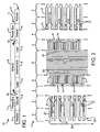
- FIG. 2 illustrates an exemplary embodiment of a first metal layer of a fluid ejection device.
- FIG. 3 illustrates an exemplary embodiment of a second metal layer of the fluid ejection device of FIG. 2 .
- FIG. 4 is a block diagram of relative positions of portions of an exemplary embodiment.
- FIGS 5A and 5B are block diagrams of relative positions of metal portions of an alternate exemplary embodiment of a fluid ejection device.
- FIG. 6 illustrates an exemplary embodiment of a first metal layer of a fluid ejection.
- FIG. 7 illustrates an exemplary embodiment of a second metal layer of the fluid ejection device of FIG. 6 .
- FIG. 8 illustrates an exemplary embodiment of a layout of a second metal layer of a fluid ejection device.
- FIG. 9 is a block diagram of the relative positions of portions of an exemplary embodiment of a fluid ejection device.
- FIG. 10 illustrates a top view of an exemplary embodiment of a fluid ejection device.
- FIG. 1 illustrates a simplified cross-sectional view of relative positions of metal layer portions in an exemplary embodiment of metal layer layouts for an exemplary fluid ejection device.
- a thin film stack 10 comprises a first metal layer 1 and a second metal layer 11.
- the first metal layer 1 comprises at least an address path portion 6 and non-address path portions.
- the non-address path portions of the first metal layer 1 may comprise at least a resistor portion 2, a first-metal-layer ground portion 4, and a logic portion 5.
- the first metal layer 1 comprises at least two each of the resistor portion 2, ground portion 4 and logic portion 5, arranged on opposite sides of the address path portion 6.
- the resistor portion 2 and associated nozzles ( FIG. 10 ) define a swath height 26.
- the resistor portion 2 comprises a plurality of resistors 21 ( FIG. 2 ).
- the address path portion 6 comprises an address bus, address lines or conductors, data paths, select or enable paths that are utilized to operate resistors that comprise resistor portion 2, as is known in the art.
- the address path portion 6 carries signals to logic elements, the logic elements causing particular firing transistors to cause particular corresponding firing resistors to fire in response to the signals.
- the logic elements include components such as transistors that provide functionality for address signal generation, fire signal coupling, select signal generation, synchronization signal generation and the like.
- the thin film stack 10 of FIG. 1 also comprises a second metal layer 11 over the first metal layer 1.
- the second metal layer 11 comprises at least a power conducting portion 7 and a second-metal-layer ground portion 8.
- the power conducting portions 7 comprise conductive paths, fire lines or power busses for providing an electrical connection to the source of electrical power for firing the resistors 21.
- the second metal layer comprises at least two power conducting portions 7 arranged on opposite sides of the ground portion 8. The power conducting portions 7 are routed, at least in part, over the first-metal-layer ground portions 4 in the first metal layer.
- the second-metal-layer ground portion 8 is routed through the swath height, substantially parallel with the column 22 of resistors 21, and over the logic portions 5 and the address path portion 6 of the first metal layer 1.
- the outboard edges of the second-metal-layer ground portion 8 overlap the inboard edges of the first-metal-layer ground portions 4.
- Conductive vias 41 FIGS. 2-4 ) provide electrical connections 42 between the first-metal-layer ground portions 4 and the second-metal-layer ground portion 8 in the second metal layer 11.
- Routing the second-metal-layer ground portion 8 through the area of the second metal layer 11 that overlies logic portions 5 and the address path portion 6 of the first metal layer 1, may result in reduced energy variation due to decreased ground resistance resulting from the greater ground area.
- Providing the second-metal-layer ground portion 8 in the second metal layer avoids costs associated with increased die sizes which result where ground resistance is decreased by widening ground paths in the first metal layer, with corresponding increases in the die size. Routing the second-metal-layer ground portion 8 through the swath height may also increase the improvements in energy variation that can be achieved by increasing the thickness of the second metal layer 11.
- FIG. 2 illustrates a top view of an exemplary layout or topology of a first metal layer 1 of an exemplary embodiment of a fluid ejection device.
- the first metal layer 1 is deposited on a substrate structure.
- the first metal layer 1 is masked and etched to define and fabricate the desired layout and topology of the first metal layer 1 of a portion of fluid ejection device circuitry.
- the first metal layer defines and comprises resistor portions 2, transistor portions 3, first-metal-layer ground portions 4, logic portions 5 and an address path portion 6.
- the resistor portions 2 each comprise a plurality of individual resistors 21.
- the resistor portions 2 also comprise heater legs 27 extending beyond the edges of an underlying transistor to provide an electrical connection to the individual resistors 21.
- the resistor portions 2 may be about 168 ⁇ m wide, the resistors being about 75 ⁇ m wide and the heater legs 27 extending about 93 ⁇ m outward from the edge of an underlying drive transistor.
- the transistor portions 3 may be about 156 ⁇ m wide, the logic portions 5 about 126 ⁇ m wide and the address path portion about 206 ⁇ m wide.
- the first-metal-layer ground portion 4 is routed over the drive transistors.
- the ground portion is about 96 ⁇ m wide.
- the resistors 21 are formed, in part, by etching away at least the conductive layer portion from the resistor portion of the first metal layer.
- the resistors 21 are arranged in columns 22, although they can be rows as well.
- FIG. 2 shows eight representative resistors 21 in a column 22.
- a column of resistors may comprise any number of resistors.
- a column of resistors can comprise, for example, 100 resistors or 168 resistors.
- the transistor portions 3 comprise drive transistor metal portions 31 of individual drive transistors associated with corresponding resistors 2.
- the drive transistor metal portions 31 are shown with representative, exemplary shapes. It is understood that the details of the form depends on the particular layout and design of the drive transistors.
- Conductive vias 32 connect the drive transistor metal portions 31 to overlying power conducting portions 7 ( FIG. 3 ).
- the drive transistor metal portions 31 connect resistors 21 to a source of electrical power, and connect source and drain portions of the drive transistors to the resistors 21 and to the ground portions 4 through vias or PSG contacts through underlying layers (not shown), for example through PSG, poly and/or gate oxide layers.
- the ground portions 4 comprise a common ground connection or path to ground running between the drive transistor metal portions 31 and the logic portion 5.
- Ground vias 41 electrically connect the first-metal-layer ground portions 4 to a second-metal-layer ground portion 8 ( FIG. 3 ) in an overlying second metal layer.
- the logic portion 5 comprises logic element metal portions 51 for individual logic elements 53 ( FIG. 4 ) which are associated with corresponding drive transistors 33 ( FIG. 4 ) and resistors 21.
- the address path portion 6 comprises a plurality of address path portions 61 which carry signals to the logic elements 53, which determine which of the individual firing resistors 21 are to be energized. For each resistor 21, corresponding drive transistors 33 and logic elements 53 operate together to receive and interpret signals from the address path portions and to switch power to the resistor to fire the resistor at appropriate times, responsive to the address signals.
- FIG. 3 illustrates a top view of an exemplary topology of a second metal layer 11 corresponding to the exemplary embodiment of FIG. 2 .
- the second metal layer 11 overlies the first metal layer 1 ( FIG. 2 ) and is deposited and fabricated using thin film techniques.
- the second metal layer 11 comprises power conducting portions 7 and a second-metal-layer ground portion 8.
- the power conducting portions 7 and the second-metal-layer ground portion 8 comprise and are defined by conductive layer portions of the second metal layer, for example, gold.
- the second metal layer 11 may also comprise a second conductive layer portion 112 underlying first conductive layer portions 113, as shown in FIG. 4 .
- FIG. 4 illustrates a top view of an exemplary topology of a second metal layer 11 corresponding to the exemplary embodiment of FIG. 2 .
- the second metal layer 11 overlies the first metal layer 1 ( FIG. 2 ) and is deposited and fabricated using thin film techniques.
- the second metal layer 11 comprises power conducting portions 7 and a second-metal
- the second-metal-layer ground portion 8 and the power conducting portions 7 comprise conductive layer portions and second conductive layer portions with substantially the same topology.
- the second conductive layer portions may extend beyond the outside edges of the conductive layer portions, for example about 4 ⁇ m beyond the edges of the conductive layer portions.
- the power conducting portions 7 are routed over, at least in part, the non-address path portions.
- the power conducting portions 7 are routed over at least a portion of the drive transistor portion 3, for example over at least a portion of the drive transistor metal portions 31 and a portion of the ground portion 4 ( FIG. 2 ).
- the second-metal-layer ground portion 8 is routed alongside and between the columns 22 of resistors 21 in the first metal layer 1, over the logic portions 5 and address portion 6 of the first metal layer 1 ( FIG. 2 ).
- the power conducting portions 7 do not overlie any portion of the address path portion 6 ( FIG. 2 ).
- the power conducting portions 7 are about 196 ⁇ m wide and the second-metal-layer ground portion 8 is about 475 ⁇ m wide.
- FIG. 4 illustrates a diagram of relative positions of the first metal layer portions and the second metal layer portions of a thin film stack 10 of an fluid ejection device for the exemplary embodiments shown in FIGS. 1-3 .
- the first metal layer 1 comprises the firing resistor portions 2, transistor portions 3, including the drive transistor metal portions 31 and the ground portions 4, logic portions 5, and the address path portion 6.
- the first metal layer 1 comprises a resistive layer portion 13 and a conductive layer portion 14.
- the resistive layer portion comprises TaAl and the conductive layer portion comprises AlCu.
- a passivation layer 12 separates the first metal layer 1 from the second metal layer 11.
- the passivation layer 12 comprises, for example, SiC and/or SiN.
- the first metal layer 1 is deposited on a substrate structure 15.
- the substrate structure 15 includes a silicon substrate, gate oxide layer, doped regions, PSG and poly layers (not shown).
- Drive transistors 33 and logic elements 53 are defined in the substrate structure 15.
- the transistor portions 3 overlie at least a portion of the drive transistors 33 and the logic portions 5 overlie the logic elements 53.
- the second metal layer 11 comprises power conducting portions 7 and a second-metal-layer ground portion 8.
- the second-metal-layer ground portion 8 overlies the address path portion 6, logic element metal portions 5 and the inboard edges of the ground portions 4.
- the second-metal-layer ground portion 8 is connected to the ground portions 4 by conductive vias 41.
- the power conducting portions 7 do not overlie the address path portion 6.
- the power conducting portions 7 are connected to the drive transistor metal portions 3 through conductive vias 32.
- the second metal layer comprises at least a first conductive layer portion 113 and may further comprise a second conductive layer portion 112.
- the second conductive layer portion 112 has a resistivity which is greater than the resistivity of the first conductive layer portion 113.
- the first conductive layer portion 113 comprises gold, which may have a resistivity of about 0.08 Ohm/sq.
- the first conductive layer portion 113 may compromise a layer of gold about 0.36 ⁇ m thick.
- the first conductive layer portion 113 may compise a layer of gold with a thickness within a range of about 0.3 ⁇ m to about 1.5 um.
- the first conductive layer portion 113 may comprise AICu.
- the second conductive layer portion 112 comprises tantalum, which may have a resistivity of about 60 ohm /sq.
- the second conductive layer portion 112 may comprise a layer of tantalum about 0.3 um thick.
- the layer of tantalum may have a thickness within a range of about 0.0 to 0.5 um.
- the second conductive layer portion may comprise, for example, tantalum. Depositing a tantalum layer portion 112 before depositing a gold layer portion 113 may improve the adhesion of the gold layer.
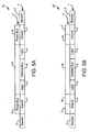
- FIG. 5A illustrates a simplified illustration of the relative layout of metal layer portions in an alternate exemplary embodiment of a thin film stack 10 of an exemplary fluid ejection device.
- the thin film stack 10 comprises a first metal layer 1 and a second metal layer 11.
- the first metal layer 1 comprises at least a resistor portion 2, a first-metal-layer ground portion 4, a logic portion 5 and an address path portion 6.
- the first metal layer comprises at least two each of a resistor portion 2, ground portion 4, and the logic portion 5, arranged on opposing sides of the address path portion 6.
- the resistor portions 2 each comprise a column 22 of individual resistors 21 ( FIG. 6 ).
- the second metal layer 11 comprises at least a power conducting portion 9 and a second conductive portion 8'.
- the second conductive portion 8' is electrically isolated from the power conducting portion 9.
- the second conductive portion 8' is routed over the address path portion 6 and logic portions 5.
- the second metal layer 11 comprises at least two power conducting portions 9, arranged on opposed sides of the second conductive portion 8'.
- FIG. 5B illustrates a simplified illustration of the relative layout of metal layer portions in an exemplary embodiment of a thin film stack 10 of an exemplary fluid ejection device.
- the second metal layer 11 comprises power conducting portions 7 and 9.
- the arrangement of FIG. 5A and the arrangement of FIG. 5B correspond to the arrangement in two different parts of the circuitry of a fluid ejection device.
- the layout of the second metal layer 11 of FIG. 5A may correspond to the layout in those portions of the second metal layer 11 of FIG. 8 where the power conducting portions 7 and 9 are routed alongside each other.
- the layout of the second metal layer 11 of FIG. 5B may correspond to the layout in the portions of the second metal layer 11 of FIG. 8 where the power conducting portions 9 are routed beyond the ends of the power conducting portions 7.
- FIGS. 5A and 5B reduce the opportunity for noise generation caused by capacitive coupling between power conducting portions and address path portions.
- Providing the second metal layer 11 with a second conductive portion 8' which comprises tantalum may reduce delamination of the second metal layer 11 from an overlying barrier layer.
- FIG. 6 illustrates a simplified top view of an alternate, exemplary embodiment of a first metal layer 1 of a fluid ejection device.
- the first metal layer comprises an address path portion 6 and non-address path portions.
- the non-address path portions comprise resistor portions 2, transistor portions 3, first-metal-layer ground portions 4 and logic portions 5.
- the resistor portion 2 comprises a plurality of individual resistors 21 arranged in a column 22.
- the transistor portion 3 comprises drive transistor metal portions 31 of individual drive transistors associated with corresponding resistors 21, and which overlie the underlying drive transistors 33 ( FIG. 9 ).
- Conductive vias 32 electrically connect the drive transistor portions 31 to overlying power conducting portions 7, 9 ( FIG. 7 ).
- the logic portions 5 overlie underlying logic elements 53 which are defined in the substrate structure 15 ( FIG. 9 ).
- the logic portions are not located as close as possible to the transistor portions 3.
- the logic portions may be separated from the transistor portions 3 by a distance greater than 5 ⁇ m.
- the logic portions 5 are about 65 ⁇ m wide and separated from the corresponding transistor portions 3 by about 134 ⁇ m.
- the logic portions 5 may be separated from corresponding transistor portions by greater than 30 ⁇ m or greater than 100 ⁇ m.
- the first-metal-layer ground portion 4 extends over the underlying transistors 33 and comprises, in part, the transistor portion 3.
- the first-metal-layer ground portion 4 is about 281 ⁇ m wide.
- the address path portion 6 is about 139 ⁇ m wide.
- FIG. 7 illustrates a simplified top view of an alternate exemplary embodiment of a second metal layer corresponding to the embodiment of the first metal layer shown in FIG. 6 .
- the second metal layer comprises power conducting portions 7 and 9, which are defined by and comprise conductive layer portions 71, 91 of the second metal layer 11.
- the second metal layer also comprises second conductive portions 72, 92 and a second conductive portion 8' which overlies the address path portion and logic element portions 5 of the underlying first metal layer.
- the second conductive portions 72, 92 may be wider than the corresponding, overlying conductive layer portions 71, 91, and may extend, for example, about 4 ⁇ m beyond the edges of the overlying conductive layer portions 71, 91.
- Second conductive layer portions 23 overlie the resistor portions 2 ( FIG. 6 ) of the underlying first metal layer.
- the second conductive layer portions 23 may protect underlying resistors 21 from damage due to cavitation.
- the second conductive portions 23, 72, 92 and 8' are separated by continuous gaps 111 in the second metal layer.
- the gaps 111 electrically separate the power conducting portions 7, 9 and their respective second conductive portions 71, 91 from one another.
- the power conducting portions 7 are electrically connected to underlying transistor portions 3 ( FIG. 6 ) of the first metal layer by conductive power vias 32.
- the power conducting portions 7 provide power to the resistors corresponding to underlying drive transistors.
- the power conducting portions 9 are routed over the ground portions 4 to provide power to drive transistors and resistors further along the columns ( FIG. 8 ).
- FIG. 8 illustrates an exemplary layout of the second metal layer 11 for the embodiments illustrated in FIGS. 5A-7 .
- the second metal layer 11 comprises six power conducting portions - four power conducting portions 7 and two power conducting portions 9, the power conducting portions being defined by conductive layer portions 71, 91 of the second metal layer 11.
- the second metal layer also comprises corresponding second conductive portions 72, 92 which extend beyond the edges of the conductive portions 71, 91 and second conductive portions 23, which overlies the resistor portion 2 ( FIG. 6 ) of the first metal layer, and second conductive portion 8', which overlies the address path portion 6.
- the second conductive portions 72, 92 extend underneath the conductive portions 71, 91 in the power conducting portions 7, 9.
- the second conductive portions 72, 92 and 8' are separated by continuous gaps 111 in the second metal layer.
- the continuous gaps 111 may be from 8 ⁇ m to 20 ⁇ m.
- Providing a second metal layer 11 with a second conductive portion 8' which comprises tantalum may reduce delamination of the second metal layer 11 from an overlying barrier layer.
- Providing a second metal layer 11 with second conductive portions 72, 92 which extend beyond the edges of conductive portions 71, 91 may prevent delamination of an overlying barrier layer from the second metal layer at the edge of the conductive portions, where the edge of the second metal layer 11 may be exposed. Delamination may be more likely to occur where gold is exposed at the edge of the conductive portions.
- the four power conducting portions 7 are routed, at least in part, over non-address path portions.
- the power conducting portions 7 are routed over at least those portions of the transistor portions and first-metal-layer ground portion 4 of an underlying first metal layer (not shown) which are associated with corresponding upper- and lower-most groups of resistors.
- the power conducting portions 9 are routed between the second conductive portions 71 and the respective power conducting portions 7. The power conducting portions 9 extend past the power conducting portions 7 to provide electrical power to groups of drive transistors and resistors toward the middle of the columns.
- FIG. 9 illustrates relative positions of portions of the first metal layer 1, second metal layer 11 and drive transistors 33 and logic elements 53 in the substrate structure 15, for the exemplary embodiments of the exemplary layouts of FIGS. 5A-8 .
- the first metal layer 1 comprises a conductive layer portion 14 and a resistive layer portion 13.
- the first metal layer 1 comprises resistor portions 2, drive transistor portions 3, first-metal-layer ground portions 4, logic element portions 5 and an address portion 6.
- the first metal layer 1 is formed over a substrate, which includes a gate oxide layer, PSG, poly and doped regions.
- Drive transistors 33 and logic elements 53 are defined in the substrate structure below the drive transistor portions 3 and logic element portions 5 respectively.
- the logic elements 53 and transistors 33 are not spaced as close to each other as possible.
- the logic elements 53 and corresponding transistors 33 are separated by a distance greater than 5 ⁇ m.
- the drive transistors 33 are about 216 ⁇ m wide and separated from corresponding logic elements 53 by 134 ⁇ m. Providing a separation between the transistor portion and the logic portion provides additional space for a wider ground portion 4, which may decrease ground resistance, thereby decreasing energy variation and improving performance of the fluid ejection device.
- a passivation layer 12 separates the first metal layer 1 from the second metal layer 11.
- the second metal layer comprises a second conductive layer portion 112 and a first conductive layer portion 113.
- the second conductive layer portion 112 comprises second conductive portions 72, 92, 8' and 23.
- the second conductive portions 72 are routed over the drive transistor portions 3, the second conductive portions 92 are routed over the first-metal-layer ground portions 4, the second conductive portion 8' is routed over the address path portion 6 and the second conductive portions 23 are routed over the resistor portions 2.
- the first conductive layer portion 113 comprises conductive portions 71, 91 which define and comprise power conducting portions 7, 9.
- the conductive portions 71, 91 are routed over the second conductive portions 72 and 92, respectively.
- no power conducting portion is routed over the address path portion 6.
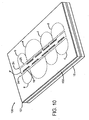
- FIG. 10 illustrates an isometric view of an exemplary embodiment of a fluid ejection device 100.
- the fluid ejection device comprises an orifice layer 101, a barrier layer 102 and a substrate structure 15.
- the orifice layer 101 may comprise an orifice plate 101, which may comprise metal.
- the orifice layer 101 comprises at least one column 24 of nozzles 25. In the embodiment of FIG. 10 , two columns 24 of nozzles 25 are shown. It is understood that an orifice layer 101 may comprise more columns 24 of nozzles 25. Each nozzle 25 corresponds to a resistor 21 in an underlying first metal layer 11.
- the nozzles 25 may be arranged in primitive groups, the nozzles 25 of each group being powered by a common power conducting portion 7 or 9 ( FIG. 8 ). In the exemplary embodiment of FIG. 10 , the nozzles 25 are arranged in six groups a-f.
- Primitive groups a, b, c, and d correspond to nozzles 25, corresponding to resistors 21 which are powered by corresponding power conducting portions 7 of the second metal layer 11 of FIG. 8 .
- the groups e and f correspond to nozzles powered by power conducting portions 9 shown in FIG. 8 .
- FIG. 10 shows a representative number of nozzles in each group. It is understood that the number of nozzles can vary.
- the groups a, b, c and d can each include at least 28 nozzles and groups e and f can include at least 116 nozzles, 58 nozzles from each column 24.
- the orifice plate 101 may comprise openings 16 through the orifice plate.
- the openings 16 overlie the second conductive portion 8' of FIG. 8 , the outlines of which are shown by the dotted line 8'.
- the openings 16 may comprise an expansion grate which accommodates and reduces the likelihood of damage from thermal expansion. Arranging the expansion grates 16 such that they overlie the second conductive portion 8', instead of overlying gold, may reduce the likelihood of delamination between the barrier layer and the second metal layer. Providing a second metal layer in which the second conductive layer portions extend beyond the edges of the conductive layer portions may reduce the likelihood of problems caused by shorts and/or delamination.
- line, bus, or path apply to any conductive path that is of sufficient conduction to provide a signal path for a particular type of signal to propagate.
Landscapes
- Engineering & Computer Science (AREA)
- Mechanical Engineering (AREA)
- Food Science & Technology (AREA)
- Particle Formation And Scattering Control In Inkjet Printers (AREA)
- Electrodes Of Semiconductors (AREA)
Applications Claiming Priority (2)
| Application Number | Priority Date | Filing Date | Title |
|---|---|---|---|
| US787573 | 2004-02-25 | ||
| US10/787,573 US7240997B2 (en) | 2004-02-25 | 2004-02-25 | Fluid ejection device metal layer layouts |
Publications (3)
| Publication Number | Publication Date |
|---|---|
| EP1568498A2 EP1568498A2 (en) | 2005-08-31 |
| EP1568498A3 EP1568498A3 (en) | 2005-12-14 |
| EP1568498B1 true EP1568498B1 (en) | 2011-12-21 |
Family
ID=34750513
Family Applications (1)
| Application Number | Title | Priority Date | Filing Date |
|---|---|---|---|
| EP04019439A Expired - Lifetime EP1568498B1 (en) | 2004-02-25 | 2004-08-16 | Fluid ejection device metal layer layouts |
Country Status (7)
| Country | Link |
|---|---|
| US (2) | US7240997B2 (ja) |
| EP (1) | EP1568498B1 (ja) |
| JP (1) | JP4323442B2 (ja) |
| KR (1) | KR101212053B1 (ja) |
| CN (2) | CN101885268B (ja) |
| SG (2) | SG131952A1 (ja) |
| TW (1) | TWI341564B (ja) |
Families Citing this family (4)
| Publication number | Priority date | Publication date | Assignee | Title |
|---|---|---|---|---|
| US7240997B2 (en) | 2004-02-25 | 2007-07-10 | Hewlett-Packard Development Company, L.P. | Fluid ejection device metal layer layouts |
| JP5539895B2 (ja) * | 2007-12-02 | 2014-07-02 | ヒューレット−パッカード デベロップメント カンパニー エル.ピー. | 電気的に絶縁されるプリントヘッドダイ接地ネットワークをフレキシブル回路で電気的に接続する方法 |
| US8444255B2 (en) | 2011-05-18 | 2013-05-21 | Hewlett-Packard Development Company, L.P. | Power distribution in a thermal ink jet printhead |
| US9701115B2 (en) | 2013-10-31 | 2017-07-11 | Hewlett-Packard Development Company, L.P. | Printheads having memories formed thereon |
Family Cites Families (15)
| Publication number | Priority date | Publication date | Assignee | Title |
|---|---|---|---|---|
| US5187500A (en) * | 1990-09-05 | 1993-02-16 | Hewlett-Packard Company | Control of energy to thermal inkjet heating elements |
| US5159353A (en) * | 1991-07-02 | 1992-10-27 | Hewlett-Packard Company | Thermal inkjet printhead structure and method for making the same |
| JPH06143574A (ja) * | 1992-11-05 | 1994-05-24 | Xerox Corp | エンハンスされた相互コンダクタンスを持つパワーmosドライバデバイスを有するサーマルインクジェットプリントヘッド |
| EP0661162B1 (en) * | 1993-12-28 | 2000-07-12 | Canon Kabushiki Kaisha | Substrate for ink-jet head, ink-jet head, and ink-jet apparatus |
| US6056391A (en) * | 1994-03-29 | 2000-05-02 | Canon Kabushiki Kaisha | Substrate having layered electrode structure for use in ink jet head, ink jet head, ink jet pen, and ink jet apparatus |
| KR960021538A (ko) * | 1994-12-29 | 1996-07-18 | 김용현 | 전해연마법을 사용한 발열방식의 잉크젯 프린트 헤드 및 그 제작방법 |
| JP2000198199A (ja) * | 1997-12-05 | 2000-07-18 | Canon Inc | 液体吐出ヘッドおよびヘッドカートリッジおよび液体吐出装置および液体吐出ヘッドの製造方法 |
| US6491377B1 (en) * | 1999-08-30 | 2002-12-10 | Hewlett-Packard Company | High print quality printhead |
| JP4604337B2 (ja) * | 2000-11-07 | 2011-01-05 | ソニー株式会社 | プリンタ、プリンタヘッド及びプリンタヘッドの製造方法 |
| US6663221B2 (en) * | 2000-12-06 | 2003-12-16 | Eastman Kodak Company | Page wide ink jet printing |
| ITTO20010266A1 (it) | 2001-03-21 | 2002-09-23 | Olivetti I Jet Spa | Substrato per una testina di stampa termica a getto d'inchiostro, in particolare del tipo a colori, e testina di stampa incorporante tale su |
| US6616268B2 (en) * | 2001-04-12 | 2003-09-09 | Lexmark International, Inc. | Power distribution architecture for inkjet heater chip |
| JP3812485B2 (ja) * | 2002-04-10 | 2006-08-23 | ソニー株式会社 | 液体吐出装置及びプリンタ |
| US6969157B2 (en) * | 2002-05-31 | 2005-11-29 | Matsushita Electric Industrial Co., Ltd. | Piezoelectric element, ink jet head, angular velocity sensor, method for manufacturing the same, and ink jet recording apparatus |
| US7240997B2 (en) | 2004-02-25 | 2007-07-10 | Hewlett-Packard Development Company, L.P. | Fluid ejection device metal layer layouts |
-
2004
- 2004-02-25 US US10/787,573 patent/US7240997B2/en active Active
- 2004-08-16 SG SG200703079-4A patent/SG131952A1/en unknown
- 2004-08-16 EP EP04019439A patent/EP1568498B1/en not_active Expired - Lifetime
- 2004-08-16 SG SG200405625A patent/SG114671A1/en unknown
- 2004-08-19 TW TW093124958A patent/TWI341564B/zh active
-
2005
- 2005-02-15 KR KR1020050012246A patent/KR101212053B1/ko active IP Right Grant
- 2005-02-23 JP JP2005046982A patent/JP4323442B2/ja active Active
- 2005-02-25 CN CN2010102209102A patent/CN101885268B/zh active Active
- 2005-02-25 CN CN2005100516887A patent/CN1660564B/zh active Active
-
2007
- 2007-06-08 US US11/811,094 patent/US7798616B2/en active Active
Also Published As
| Publication number | Publication date |
|---|---|
| SG131952A1 (en) | 2007-05-28 |
| US7240997B2 (en) | 2007-07-10 |
| US20050185022A1 (en) | 2005-08-25 |
| US20070242110A1 (en) | 2007-10-18 |
| JP4323442B2 (ja) | 2009-09-02 |
| CN1660564B (zh) | 2010-09-29 |
| KR20060041941A (ko) | 2006-05-12 |
| CN1660564A (zh) | 2005-08-31 |
| EP1568498A3 (en) | 2005-12-14 |
| KR101212053B1 (ko) | 2012-12-13 |
| TW200529330A (en) | 2005-09-01 |
| TWI341564B (en) | 2011-05-01 |
| SG114671A1 (en) | 2005-09-28 |
| CN101885268A (zh) | 2010-11-17 |
| EP1568498A2 (en) | 2005-08-31 |
| US7798616B2 (en) | 2010-09-21 |
| JP2005238843A (ja) | 2005-09-08 |
| CN101885268B (zh) | 2012-06-13 |
Similar Documents
| Publication | Publication Date | Title |
|---|---|---|
| US5103246A (en) | X-Y multiplex drive circuit and associated ink feed connection for maximizing packing density on thermal ink jet (TIJ) printheads | |
| US7344227B2 (en) | Power and ground buss layout for reduced substrate size | |
| EP2173560B1 (en) | Printheads | |
| EP1621347B1 (en) | Ink jet head substrate, ink jet head, and method of manufacturing an ink jet head susbstrate | |
| US7798616B2 (en) | Fluid ejection device metal layer layouts | |
| TWI721652B (zh) | 用於列印頭之晶粒及其形成方法,及列印頭 | |
| US20030128255A1 (en) | Fluid injection head structure and method thereof | |
| JP2840271B2 (ja) | 記録ヘッド | |
| US11981133B2 (en) | Liquid discharge head substrate and printing apparatus | |
| US12083798B2 (en) | Thermal inkjet printhead, a printing assembly comprising the thermal inkjet printhead and a printing apparatus comprising the thermal inkjet printhead | |
| KR20210113285A (ko) | 인쇄헤드용 다이 | |
| US6905196B2 (en) | Polysilicon feed-through fluid drop ejector | |
| CN113396066A (zh) | 用于打印头的管芯 | |
| JP3222148B2 (ja) | 熱インク・ジェット・プリントヘッド用多重回路付きインク供給構造および熱インク・ジェット・プリントヘッド | |
| CN100368202C (zh) | 喷墨打印头芯片 | |
| JP2019194005A (ja) | 液体吐出ヘッド用基板、液体吐出ヘッド用基板の製造方法、および液体吐出ヘッド | |
| EP0465212A2 (en) | Ink jet printheads | |
| JP2001130008A (ja) | モノリシックインクジェットヘッドの製造方法 |
Legal Events
| Date | Code | Title | Description |
|---|---|---|---|
| PUAI | Public reference made under article 153(3) epc to a published international application that has entered the european phase |
Free format text: ORIGINAL CODE: 0009012 |
|
| AK | Designated contracting states |
Kind code of ref document: A2 Designated state(s): AT BE BG CH CY CZ DE DK EE ES FI FR GB GR HU IE IT LI LU MC NL PL PT RO SE SI SK TR |
|
| AX | Request for extension of the european patent |
Extension state: AL HR LT LV MK |
|
| PUAL | Search report despatched |
Free format text: ORIGINAL CODE: 0009013 |
|
| AK | Designated contracting states |
Kind code of ref document: A3 Designated state(s): AT BE BG CH CY CZ DE DK EE ES FI FR GB GR HU IE IT LI LU MC NL PL PT RO SE SI SK TR |
|
| AX | Request for extension of the european patent |
Extension state: AL HR LT LV MK |
|
| 17P | Request for examination filed |
Effective date: 20051201 |
|
| AKX | Designation fees paid |
Designated state(s): DE FR GB NL |
|
| 17Q | First examination report despatched |
Effective date: 20071022 |
|
| GRAP | Despatch of communication of intention to grant a patent |
Free format text: ORIGINAL CODE: EPIDOSNIGR1 |
|
| GRAS | Grant fee paid |
Free format text: ORIGINAL CODE: EPIDOSNIGR3 |
|
| GRAA | (expected) grant |
Free format text: ORIGINAL CODE: 0009210 |
|
| AK | Designated contracting states |
Kind code of ref document: B1 Designated state(s): DE FR GB NL |
|
| REG | Reference to a national code |
Ref country code: GB Ref legal event code: FG4D |
|
| REG | Reference to a national code |
Ref country code: DE Ref legal event code: R096 Ref document number: 602004035730 Country of ref document: DE Effective date: 20120308 |
|
| REG | Reference to a national code |
Ref country code: NL Ref legal event code: T3 |
|
| PLBE | No opposition filed within time limit |
Free format text: ORIGINAL CODE: 0009261 |
|
| STAA | Information on the status of an ep patent application or granted ep patent |
Free format text: STATUS: NO OPPOSITION FILED WITHIN TIME LIMIT |
|
| 26N | No opposition filed |
Effective date: 20120924 |
|
| REG | Reference to a national code |
Ref country code: DE Ref legal event code: R097 Ref document number: 602004035730 Country of ref document: DE Effective date: 20120924 |
|
| REG | Reference to a national code |
Ref country code: FR Ref legal event code: PLFP Year of fee payment: 13 |
|
| REG | Reference to a national code |
Ref country code: FR Ref legal event code: PLFP Year of fee payment: 14 |
|
| REG | Reference to a national code |
Ref country code: FR Ref legal event code: PLFP Year of fee payment: 15 |
|
| PGFP | Annual fee paid to national office [announced via postgrant information from national office to epo] |
Ref country code: NL Payment date: 20230721 Year of fee payment: 20 |
|
| PGFP | Annual fee paid to national office [announced via postgrant information from national office to epo] |
Ref country code: GB Payment date: 20230720 Year of fee payment: 20 |
|
| PGFP | Annual fee paid to national office [announced via postgrant information from national office to epo] |
Ref country code: FR Payment date: 20230720 Year of fee payment: 20 Ref country code: DE Payment date: 20230720 Year of fee payment: 20 |
|
| REG | Reference to a national code |
Ref country code: DE Ref legal event code: R071 Ref document number: 602004035730 Country of ref document: DE |
|
| REG | Reference to a national code |
Ref country code: NL Ref legal event code: MK Effective date: 20240815 |
|
| REG | Reference to a national code |
Ref country code: GB Ref legal event code: PE20 Expiry date: 20240815 |
|
| PG25 | Lapsed in a contracting state [announced via postgrant information from national office to epo] |
Ref country code: GB Free format text: LAPSE BECAUSE OF EXPIRATION OF PROTECTION Effective date: 20240815 |
|
| PG25 | Lapsed in a contracting state [announced via postgrant information from national office to epo] |
Ref country code: GB Free format text: LAPSE BECAUSE OF EXPIRATION OF PROTECTION Effective date: 20240815 |