EP1568331A1 - Radio-frequency based catheter system and hollow co-axial cable for ablation of body tissues - Google Patents
Radio-frequency based catheter system and hollow co-axial cable for ablation of body tissues Download PDFInfo
- Publication number
- EP1568331A1 EP1568331A1 EP05011329A EP05011329A EP1568331A1 EP 1568331 A1 EP1568331 A1 EP 1568331A1 EP 05011329 A EP05011329 A EP 05011329A EP 05011329 A EP05011329 A EP 05011329A EP 1568331 A1 EP1568331 A1 EP 1568331A1
- Authority
- EP
- European Patent Office
- Prior art keywords
- catheter
- electrically conductive
- radio
- ablating
- ablating element
- Prior art date
- Legal status (The legal status is an assumption and is not a legal conclusion. Google has not performed a legal analysis and makes no representation as to the accuracy of the status listed.)
- Granted
Links
Images


Classifications
-
- A—HUMAN NECESSITIES
- A61—MEDICAL OR VETERINARY SCIENCE; HYGIENE
- A61B—DIAGNOSIS; SURGERY; IDENTIFICATION
- A61B18/00—Surgical instruments, devices or methods for transferring non-mechanical forms of energy to or from the body
- A61B18/04—Surgical instruments, devices or methods for transferring non-mechanical forms of energy to or from the body by heating
-
- A—HUMAN NECESSITIES
- A61—MEDICAL OR VETERINARY SCIENCE; HYGIENE
- A61B—DIAGNOSIS; SURGERY; IDENTIFICATION
- A61B18/00—Surgical instruments, devices or methods for transferring non-mechanical forms of energy to or from the body
- A61B18/18—Surgical instruments, devices or methods for transferring non-mechanical forms of energy to or from the body by applying electromagnetic radiation, e.g. microwaves
-
- A—HUMAN NECESSITIES
- A61—MEDICAL OR VETERINARY SCIENCE; HYGIENE
- A61B—DIAGNOSIS; SURGERY; IDENTIFICATION
- A61B18/00—Surgical instruments, devices or methods for transferring non-mechanical forms of energy to or from the body
- A61B18/04—Surgical instruments, devices or methods for transferring non-mechanical forms of energy to or from the body by heating
- A61B18/12—Surgical instruments, devices or methods for transferring non-mechanical forms of energy to or from the body by heating by passing a current through the tissue to be heated, e.g. high-frequency current
- A61B18/14—Probes or electrodes therefor
- A61B18/1492—Probes or electrodes therefor having a flexible, catheter-like structure, e.g. for heart ablation
-
- A—HUMAN NECESSITIES
- A61—MEDICAL OR VETERINARY SCIENCE; HYGIENE
- A61B—DIAGNOSIS; SURGERY; IDENTIFICATION
- A61B18/00—Surgical instruments, devices or methods for transferring non-mechanical forms of energy to or from the body
- A61B18/18—Surgical instruments, devices or methods for transferring non-mechanical forms of energy to or from the body by applying electromagnetic radiation, e.g. microwaves
- A61B18/1815—Surgical instruments, devices or methods for transferring non-mechanical forms of energy to or from the body by applying electromagnetic radiation, e.g. microwaves using microwaves
-
- A—HUMAN NECESSITIES
- A61—MEDICAL OR VETERINARY SCIENCE; HYGIENE
- A61B—DIAGNOSIS; SURGERY; IDENTIFICATION
- A61B17/00—Surgical instruments, devices or methods, e.g. tourniquets
- A61B17/00234—Surgical instruments, devices or methods, e.g. tourniquets for minimally invasive surgery
- A61B2017/00292—Surgical instruments, devices or methods, e.g. tourniquets for minimally invasive surgery mounted on or guided by flexible, e.g. catheter-like, means
- A61B2017/003—Steerable
-
- A—HUMAN NECESSITIES
- A61—MEDICAL OR VETERINARY SCIENCE; HYGIENE
- A61B—DIAGNOSIS; SURGERY; IDENTIFICATION
- A61B18/00—Surgical instruments, devices or methods for transferring non-mechanical forms of energy to or from the body
- A61B2018/00636—Sensing and controlling the application of energy
- A61B2018/00773—Sensed parameters
- A61B2018/00839—Bioelectrical parameters, e.g. ECG, EEG
-
- A—HUMAN NECESSITIES
- A61—MEDICAL OR VETERINARY SCIENCE; HYGIENE
- A61B—DIAGNOSIS; SURGERY; IDENTIFICATION
- A61B18/00—Surgical instruments, devices or methods for transferring non-mechanical forms of energy to or from the body
- A61B18/04—Surgical instruments, devices or methods for transferring non-mechanical forms of energy to or from the body by heating
- A61B18/12—Surgical instruments, devices or methods for transferring non-mechanical forms of energy to or from the body by heating by passing a current through the tissue to be heated, e.g. high-frequency current
- A61B18/14—Probes or electrodes therefor
- A61B2018/1405—Electrodes having a specific shape
- A61B2018/1407—Loop
-
- A—HUMAN NECESSITIES
- A61—MEDICAL OR VETERINARY SCIENCE; HYGIENE
- A61B—DIAGNOSIS; SURGERY; IDENTIFICATION
- A61B18/00—Surgical instruments, devices or methods for transferring non-mechanical forms of energy to or from the body
- A61B18/04—Surgical instruments, devices or methods for transferring non-mechanical forms of energy to or from the body by heating
- A61B18/12—Surgical instruments, devices or methods for transferring non-mechanical forms of energy to or from the body by heating by passing a current through the tissue to be heated, e.g. high-frequency current
- A61B18/14—Probes or electrodes therefor
- A61B2018/1405—Electrodes having a specific shape
- A61B2018/1435—Spiral
- A61B2018/1437—Spiral whereby the windings of the spiral touch each other such as to create a continuous surface
-
- A—HUMAN NECESSITIES
- A61—MEDICAL OR VETERINARY SCIENCE; HYGIENE
- A61B—DIAGNOSIS; SURGERY; IDENTIFICATION
- A61B18/00—Surgical instruments, devices or methods for transferring non-mechanical forms of energy to or from the body
- A61B18/18—Surgical instruments, devices or methods for transferring non-mechanical forms of energy to or from the body by applying electromagnetic radiation, e.g. microwaves
- A61B18/1815—Surgical instruments, devices or methods for transferring non-mechanical forms of energy to or from the body by applying electromagnetic radiation, e.g. microwaves using microwaves
- A61B2018/1861—Surgical instruments, devices or methods for transferring non-mechanical forms of energy to or from the body by applying electromagnetic radiation, e.g. microwaves using microwaves with an instrument inserted into a body lumen or cavity, e.g. a catheter
-
- A—HUMAN NECESSITIES
- A61—MEDICAL OR VETERINARY SCIENCE; HYGIENE
- A61B—DIAGNOSIS; SURGERY; IDENTIFICATION
- A61B90/00—Instruments, implements or accessories specially adapted for surgery or diagnosis and not covered by any of the groups A61B1/00 - A61B50/00, e.g. for luxation treatment or for protecting wound edges
- A61B90/39—Markers, e.g. radio-opaque or breast lesions markers
Landscapes
- Health & Medical Sciences (AREA)
- Surgery (AREA)
- Life Sciences & Earth Sciences (AREA)
- Engineering & Computer Science (AREA)
- Heart & Thoracic Surgery (AREA)
- Medical Informatics (AREA)
- Otolaryngology (AREA)
- Veterinary Medicine (AREA)
- Physics & Mathematics (AREA)
- Biomedical Technology (AREA)
- Public Health (AREA)
- Nuclear Medicine, Radiotherapy & Molecular Imaging (AREA)
- Molecular Biology (AREA)
- Animal Behavior & Ethology (AREA)
- General Health & Medical Sciences (AREA)
- Electromagnetism (AREA)
- Plasma & Fusion (AREA)
- Cardiology (AREA)
- Surgical Instruments (AREA)
- Materials For Medical Uses (AREA)
Abstract
Description
- The present application is a continuation-in-part of U.S. patent application Serial No. 09/211,188, filed December 14, 1998, currently pending before the United States Patent and Trademark Office.
- This invention relates generally to radio-frequency ("RF") powered medical apparatus and ablation of biological tissues. More particularly, this invention concerns catheter-based RF antenna for ablating biological tissues within the body vessel of a patient and for the treatment of cardiac arrhythmias.
- In recent years medical devices have gained significant acceptance in the medical community as an important treatment modality for heart diseases and other serious ailments, which were traditionally remedied by medication or surgical operation. Two fundamental trends have emerged in the treatment of cardiac diseases. The first has been the shift from open-heart surgical procedures to less invasive and less expensive catheter-based treatments, which are safer and less debilitating.
- The second trend is represented by the shift from the use of anti-arrhythmic drugs to minimally invasive catheters or other device-based therapies to palliate incurable arrhythmias. For example, automatic cardioverter-defibrillator are routinely implanted in patients with lethal ventricular arrhythmias to reduce the likelihood of sudden death. Thus, radio-frequency (RF") catheter ablation is now being performed in large number of patients suffering from cardiac arrhythmias.
- Despite these advances in technology, atrial fibrillation ("AF") remains a significant challenge. AF, a rapid irregular rhythm in the atria or upper chambers of the heart induced by non-uniformed electrical pulses, represents a leading cause of stroke and heart attack and a major health care burden. To date, the most effective surgical procedure for the treatment of AF has been the Maze procedure undertaken in "open-heart" surgery. In the Maze procedure, incisions are made along predetermined lines exterior of the atrium, which are then sutured together. As healing develops, scars are formed along the incision lines thereby forming barriers to the conduction of electrical impulses. By creating such barriers, AF can no longer be sustained and regular heart rhythm is restored. However, the Maze procedure has not been widely adopted due to the morbidity and mortality associated with open-heart surgery, which involves the opening of the chest cavity and cutting of the chest bones.
- One new approach to mimic the Maze operation is represented by catheter-based radio-frequency ablation technique, wherein, instead of surgical incisions, a catheter-electrode is applied to destroy or ablate the heart tissues inside the atrial chamber. The catheter-electrode is passed through the artery for access to the atrium, as commonly practiced in the medical field. Within the atrium, the tip of the catheter-electrode is positioned, usually with the aid of x-ray or fluoroscopic means, and is brought into contact with the heart tissue at a desired location or spot where ablation is required. At this spot, the tissue is destroyed by resistive heating generated from the catheter-electrode. Thereafter, the catheter-electrode is re-positioned to the next spot for ablation. A series of spot ablations thus mimics the lineal lesions as accomplished under the Maze procedure against the conduction of electrical impulses.
- Existing catheter-based ablation procedures are recognizably less intrusive than "open-heart" surgery. In addition, during the ablation, disruption of cardiovascular function is reduced. However, a successful catheter-based radio-frequency ablation procedure requires the ablation of tissue spots within the spatial or proximity tolerance between adjacent spots, usually less than 2 millimeters, to prevent the passage of electrical impulses. In that connection, the task for the precise placement of the catheter-electrode represents a critical element of a successful procedure.
- A major drawback of such existing procedures is in the time-consuming task in positioning the catheter-electrode at the desired ablation spots within the atrium while the heart chamber muscles are pulsating. Movements of atrial wall or the heart muscles often render accurate placement of the catheter-electrode difficult, and slippage of the catheter-electrode tends to occur thereby damaging portions of the atrium where ablation is not desired. As a result, placement of the catheter based RF ablation cannot be efficiently accomplished, and prolonged procedure time, in excess of 12 hours, can be expected. Further, during the procedure, x-ray or other irradiating means are routinely employed for locating and positioning the catheter-electrode, which dictates the use of heavy lead protective gear by the electro-physiologist. As a result, such inconvenience is often amplified by the prolonged procedure time, which detracts from the use of catheter-based electrode as an efficient means for tissue ablation.
- To minimize the risk of slippage, for example, in U.S. Patent No. 5,741,249, a catheter-based microwave antenna is disclosed wherein a distal tip is incorporated into the antenna to anchor it to the atrial wall. However, while this design reduces the likelihood of antenna or catheter-electrode slippage during each ablation step, it does not eliminate the consuming task to secure precise placement of the antenna along the desired ablation path for each ablation step. Thus after each ablation step, the antenna has to be re-positioned and anchored precisely at the next spot which must be located within the spatial or proximity tolerance on the ablation path as referenced above.
- Accordingly, effective treatments for atrial fibrillation with catheter ablation will require the creation of long or overlapping lineal or curvilineal ablation lesions on the inner surface of the atrium. These lesions can then act as barriers to the conduction of electrical impulses, thus preventing atrial fibrillation.
- It is also recognized that a critical requirement for the effective catheter-based ablation of atrial fibrillation is the ability to stabilize and anchor the catheter and microwave antenna inside the atrial chambers. New catheter ablation systems, preferably capable of producing long or overlapping lineal or curvilineal ablation lesions, are required for the development of minimally invasive catheter-based curative procedures for atrial fibrillation.
- US Patent 5,776,176 is concerned with microwave thermal ablation of tissue and discloses a microwave antenna which is insertable into a cardiovascular catheter and is formed from a coaxial cable including an inner conductor and a an inner insulator with the inner insulator having a reduced diameter portion adjacent a distal end of the catheter.
- According to the invention, there is provided a method of ablating body tissue, comprising
- providing a catheter at a targeted ablation site, the catheter including a deployable guide;
- providing a deployable ablating member including an
ablating element to deliver radio-frequency frequency energy to
body tissue and an electrical hollow cable to conduct radio-frequency
energy between a radio-frequency energy source and the
ablating element, the electrical hollow cable comprising:
- (a) a first elongated electrically conductive tubular member coupled to the ablating element;
- (b) a second elongated electrically conductive tubular member coupled to the ablating element and disposed in a substantially co-axial relationship over the first elongated tubular member substantially throughout the length of the cable;
- (c) an elongated tubular dielectric member directly disposed between the first and second elongated electrically conductive tubular members without an air gap therebetween; and
- (d) an axial lumen through which the deployable guide is slidably received within;
- deploying the deployable guide out of the catheter at the targeted ablation site;
- deploying the ablating member out of the catheter by sliding the electrical hollow cable over the deployable guide; and
- ablating the body tissue with the ablating element.
- Further optional features of the invention are set out in Claims 2 to 15. In particular, the antenna guide can be formed as an elongated flexible member having a detached distal end portion that is terminated with a distal tip.
- The radio-frequency catheter system of the present invention can also incorporate various alternate radio-frequency antenna designs. In one such alternate embodiment of the present invention, the radio-frequency antenna comprises a monopole bead disposed at the distal portion of the catheter for delivering an optimal radiation pattern while minimizing refection and voltage standing wave ratios. In another alternate embodiment of the present invention, a microstrip flexcircuit is provided.
- In application, the antenna guide is deployed out of the catheter lumen to establish contact with the interior surface of the body vessel. The flexibility of the antenna guide enables it to flex to conform to the contour of the body vessel to define the ablation pathway for the radio-frequency antenna.
- The present invention effectively reduces if not avoids the need for repetitive pin-point precision placement of the ablation catheter electrode of the prior art. The present invention conveniently places the radio-frequency antenna along the locus of an antenna guide which defines the tissue ablation pathway. At the same time, the present invention ensures a continuous ablation pathway and substantially reduces the risk of electrical impulse leakage between ablated spots of the prior art. Accordingly, the present invention substantially accomplishes the objective of the Maze procedure in achieving curvilineal lesions yet without the need for open-heart surgery.
- These and other aspects and advantages of the invention will become apparent from the following detailed description, and the accompanying drawings, which illustrate by way of example the features of the invention.
-
- Figure 1 is a conceptual diagram of a radio-frequency catheter ablation system of the present invention, together with radio-frequency power module, computer control and data recording device.
- Figure 2 is a perspective view of the radio-frequency catheter ablation system of the present invention.
- Figure 3A is a sectional view of the antenna guide and the radio-frequency antenna in a deployed position at the distal portion of the radio-frequency catheter ablation system.
- Figure 3B is a sectional view of the antenna guide and the radio-frequency antenna in a retracted position at the distal portion of the radio-frequency catheter ablation system.
- Figure 4A is a.partial sectional view of the distal portion of the radio-frequency catheter ablation system.
- Figure 4B is a partial sectional view of the distal portion of another embodiment of the radio-frequency catheter ablation system.
- Figure 5 is sectional view of the radio-frequency antenna and a partial view of the antenna guide.
- Figure 6 is a cross-sectional view taken from line 6-6 of Fig. 5.
- Figure 7 is a perspective view of another embodiment of the present invention.
- Figure 8 is a typical cross-sectional view of distal portion of the catheter system.
- Figure 9 is a plan view of a microstrip used for electrical connection between the radio-frequency antenna and a source of the radio-frequency energy.
- Figure 10 is an elevational view of the microstrip of Figure 9.
- Figure 11 is a partial sectional view of the radio-frequency catheter ablation system.
- Figure 12 is a partial sectional view of a handle chassis used in the radio-frequency catheter ablation system.
- Figure 13 is a cross-sectional view of the microstrip disposed within the handle chassis of Fig. 12.
- Figure 14 is a partial sectional view of another embodiment of present invention incorporating a design of a monopole radio-frequency antenna.
- Figure 15 is a partial sectional view of another embodiment of the present invention incorporating a design of a microstrip flexcircuit radio-frequency antenna.
- Figure 16 is a cross-sectional view of the microstrip flexcircuit taken from line 16-16 of Fig. 15.
- Figure 17 is a partial cut-away view of the distal portion of a hollow cable of the present invention for use in a radio-frequency catheter ablation system.
- Figure 18 is a partial sectional view of the distal portion of the catheter of the present invention incorporating one or more steering wires.
- Figure 19 is another partial sectional view of the distal portion of the catheter of the present invention deflected by one or more steering wires.
-
- The current invention provides an improved radio frequency-based catheter system for ablating biological tissues within the body vessel of a patient. The system includes a catheter that is adaptable for insertion into a body vessel of patient. It incorporates a deployable radio- frequency antenna for delivering electromagnetic energy to the treatment site. A monorail guide is provided for precise positioning of the antenna along a desired ablation pathway. The present invention also provides a hollow co-axial cable for conducting electromagnetic energy.
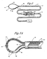
- As seen in Figs. 1, 2, and 3, the present invention comprises a
catheter 3, which is adapted for insertion into a body vessel of the patient. The catheter has a flexible elongatedtubular body 10 with aproximal portion 12 and adistal portion 14. Alumen 16 extends from the proximal portion of the catheter to the distal portion with a distal opening 18 (Figs. 3 and 4). Located at theproximal portion 12 ofcatheter 3 is ahandle chassis 20 for housing necessary steering and positioning controls, as will be described in further details below. Incorporated at the proximal end of thecatheter 3 is acoupling 22 for connecting various electrodes (not shown) in support of the ablation procedure. - The dimensions of
catheter 3 are adapted as required to suit the particular medical procedure, which are well known in the medical art. Thetubular body 10 of the catheter is generally constructed of polymer materials that are bio-compatible within the body vessel environment. Examples of these materials include Pebax from Autochem Germany, polyethylene, polyurethane, polyester, polyimide and polyamide, with varying degrees of radio-pacificity, hardness and elasticity. - In one embodiment of the present invention, the
catheter 3 is formed with a plurality of segments using one or more of the afore-mentioned materials such that the catheter body is progressively more flexible toward its distal end. The segments are joined together via thermal bonding, butt joint, or adhesive bonding. Braiding reinforcement can also be added to the circumferential surface oftubular body 10 to attain the desirable level of stiffness and torsional strength for the catheter. This allows the catheter to advance and negotiate through the body vessel of a patient, and to enable torque transfer along the length of the catheter from the proximal portion to the distal portion. - The
distal portion 14 ofcatheter 3 consists of a softer polymer compound with little or no braiding to provide the desired flexibility to accommodate distal deflection or steering of thecatheter 3 when it is maneuvered through the narrow passageways of body vessels such as arteries or veins. In the present invention, steering of the catheter is implemented by apull wire 30, which extends from thecontrol handle chassis 20 to thedistal portion 14 of thecatheter 3, as shown in Fig. 11. - At the distal end of
catheter 3, pullwire 30 is affixed to the inner wall of thecatheter lumen 16 by soldering or other suitable means. - Pull
wire 30 is proximally fastened to deflection control grip orthumb slide 32, which is slidably engaged along alongitudinal slot 34 of thehandle chassis 20. Longitudinal movement of thethumb slide 32 alongslot 34, together with the torsional movement of thecatheter 3 enables a physician to bend or straighten thecatheter 3 as needed in order to negotiate through the passageways of the body vessel. Incorporated in thethumb slide 32 is frictional capture means for affixing the grip position in theslot 34. Many such means are commercially available. Examples of such means include set-release, pressure switch or self-locking mechanisms. - The catheter system 1 of the present invention provides an effective means for guiding a RF antenna for tissue ablation along a predetermined ablation pathway. Figs. 1, 3A, 4A and 4B show an antenna guide or
monorail 36, which is deployed in an extended position adjacent thedistal portion 14 ofcatheter 3. The antenna guide ormonorail 36 is also adaptable to be retracted within thecatheter lumen 16 as shown in Fig. 3B. - In one embodiment of the present invention,
monorail 36 comprises a flexible elongated member, which can be constructed of a strip-like material. Alternatively,monorail 36 can also be made of small-diameter tubing, as shown in the drawings.Monorail 36 has extendedportions handle chassis 20, monorail extension portions are secured to respective control slides 46 and 48. Similar to the catheter deflection pullwire 30, control slides 46 and 48 are slidably engaged within longitudinal slots on thehandle chassis 20, as shown in Fig. 2, and are moveable distally or proximally along the longitudinal axis of thecatheter 3. Thus by moving one or both control slides, the monorail guide can establish a deployed position, as shown in Figs. 2, and 3A, or a retracted position, Fig. 3B. For deployment of themonorail 36, either one or both control slides 46 and 48 are moved distally relative to thehandle chassis 20. For retraction, the control slides are moved proximally. The positions of the control slides can be secured with appropriate means such as spring-loaded frictional capture means or the like, as similar to those used for the deflection control orthumb slide 32. - Fig. 3B shows the
monorail 36 in a substantially retracted position, where it is arranged in a compact U-shaped fashion within thecatheter lumen 16 at thedistal portion 14 of thecatheter 3. A smooth orcurved tip 40 is provided at themonorail 36 such that in the retracted position,tip 40 substantially closes thedistal opening 18 ofcatheter 3 to isolate thecatheter lumen 16 from the biological environment. Thetip 40 also renders the catheter "atraumatic" and provides a smooth distal profile for the catheter to reduce the risks of body vessel puncture as it is navigated through the passageways of the body vessels. -
Tip 40 can be made of bio-compatible materials which are commonly used for the construction of catheters. Further it can incorporate a radio-opaque material to aid in the identification of its location within the body vessel by X-rays or other fluoroscopic means, as commonly practiced in the art. - The
monorail 36 is made of materials in either metallic or in the polymer group having appropriate degree of memory, bio-compatibility, and spring-like structural properties. Examples of such materials include nitinol (nickel-titanium), stainless steel, polyamide and polytetrafluroethylene ("PTFE"). Metallic materials used can also be heat treated or cold worked as necessary to provide the desirable structural properties, such as stiffness and flexibility. These structural properties allowmonorail 36 to be moved without crinkles within thecatheter lumen 16. However, in its deployed position outside thecatheter lumen 16, themonorail 36 is adaptable to flex. -
Monorail 36 is deployable beyond thedistal opening 18 of thecatheter 3 within a body vessel to form a substantiallycontinuous loop 50 as shown in Figs. 3A, 4A and 4B. Monorail deployment is enabled with the longitudinal advancement of control slides 46 and 48 toward the distal end ofcatheter 3 such that the monorail extends beyond the catheterdistal opening 18 to establish contact with the interior wall of the body vessel. Upon such contact, the extended portion ofmonorail 36 will flex to acquire a loop configuration. Depending on the interior contour the body vessel where treatment is desired, the size of theloop 50 can be adapted by adjusting the amount of distal displacement of the control slides such that the monorail conforms to the contour of the body vessel. The spring-like properties of themonorail 36 make possible that at least a portion of theloop 50 bears against the wall of the body vessel thereby acquiring line contact with the interior wall of the body vessel in spite of its possible movements. Thetip 40 further helps in anchoring themonorail 36 at crevices or minor depressions on the interior wall of the body vessel without the risks of causing puncture on the body vessel. - To ascertain the position of the
monorail 36 when it is being advanced within a body vessel, one or more radio-opaque markers can be installed on themonorail 36. As shown in Figs. 1 - 4, a radio-opaque marker is incorporated intotip 40 of themonorail 36. With the radio-opaque material,tip 40 becomes opaque under x-ray or fluoroscopic examination, thereby aiding the identification of its position during catheter insertion or tissue ablation. The structure and use of radio-opaque markers are well-known in the art, and are not detailed here. - As a variation in design, the antenna guide can be constructed of two separate elongated members joined at the distal tip to form a unitary monorail. The joint angle between the elongated members can be pre-determined based on the profile of the monorail as it is needed for the particular application. Thus by way of example, a low profile (having ultra small cross-section) catheter used in operation within a narrow lumen of a body vessel could require a relatively small joint angle for the elongated members so as to facilitate the monorail retraction and deployment. Fig. 4B shows another embodiment of the present invention, wherein one end of the
monorail guide 36a is secured to thecatheter 3 adjacent thedistal opening 18. The other end of themonorail 36a, which incorporates an extension portion 44a, is attached to a control slide (not shown) at the handle chassis. This embodiment enables the deployment and retraction of the monorail with the use of a single control slide at the handle chassis. - The present invention includes a radio-frequency (RF)
antenna 54 disposed adjacent thedistal portion 14 of thecatheter 3, as shown in Figs. 2 - 7, for tissue ablation. In an representative embodiment of the present invention, theRF antenna 54 includes an electrically conductive material or wire strip that is wound in a helical fashion to form ahelical coil 56. The appropriate diameter, pitch and length of the coil winding, and the selection of the conductive material or wire strip are a matter of design choice, which can vary according to the particular procedure requirements as known in the art. Thus these design elements and considerations are not detailed here. - As shown in Figs. 2, 3 and 4A and 4B, the
RF antenna 54 includes thehelical coil 56, which defines anaxial passageway 58 for accommodating themonorail 36. TheRF antenna 54 is slidably mounted over themonorail 36. Thus its movement will be prescribed by the monorail. - To enhance its shape integrity,
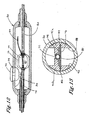
RF antenna 54 is provided with a tubular liner orsleeve 60, which has a flexible extended body extending from thehelical coil 56 proximally toward theproximal portion 12 of thecatheter 3.Sleeve 60 is constructed of a dielectric material, which reduces the likelihood of electrical short between the metallic surfaces ofhelical coil 56 and body fluids in thepassageway 58, and to help confine the electro-magnetic field to the outside of the passageway. - As shown in Figs. 5 and 6,
helical coil 56 is coupled at contact points 65 to a first or inner electrically conductive member orconductor 64, which is in turn electrically coupled to a source of RF energy provided by the RFpower control source 5. In the embodiment shown in Figs. 5, 6, 11 and 17,inner conductor 64 is made of a flexible mesh or braided wired construction, or made of a thin-film electrically conductive material, which circumscribes theouter surface 62 ofsleeve 60 and extends proximally from thehelical coil 56 to thehandle chassis 20. In this embodiment,inner conductor 64 assumes an elongated tubular configuration. -
Inner conductor 64 is coated with a polymeric dielectricprotective coating 68 along its outer circumferential surface and extends proximally to the handle chassis.Protective coating 68 serves as a substrate for thehelical coil 56 and for a second electrically conductive member orouter conductor 66.Protective coating 68 also electrically isolates theinner conductor 64 from theouter conductor 66. - As shown in Figs. 5 and 6,
helical coil 56 is wound around the outer circumferential surface of theprotective coating 68 and is connected toouter conductor 66 atcontact point 67. In turn,outer conductor 66 is electrically coupled to the source of RF energy provided by the RFpower control source 5. - In the embodiment as shown in Figs. 5 and 6,
outer conductor 66 is made of an electrically conductive material circumscribing the dielectricprotective coating 68, and extends from thehelical coil 56 proximally toward thehandle chassis 20. The outer conductor can be made of braided wired construction or thin film electrically conductive material. - As shown in Fig. 5, the
helical coil 56 is coated with a polymericdielectric encapsulant 70 along its outer circumferential surface to ensure the structural integrity of the helical coil and to protect same from the biological environment.Encapsulant 70 is made of suitable materials such as silicon or polymer-based, materials or rubber compounds. Similarly, anouter jacket 72 made of similar materials is provided to encase theouter conductor 66 and to provide electromagnetic and thermal isolation from the biological environment. - As shown in Fig. 11,
outer jacket 72 is coupled to amicrostrip 80, which is slidably secured to thehandle chassis 20 for the axial displacement of the RF antenna at the proximal portion, as will be discussed in more details below. Theextended portion 44 ofmonorail 36 extends proximally within thepassageway 58 to theproximal portion 12 of thecatheter 3. Thus the present invention provides for a set of electrical conductors each of which is formed in an elongated tubular configuration and arranged in a substantially coaxially aligned relationship with each other to form a hollow cable which extends from thehelical coil 56 proximally to thehandle chassis 20 for the delivery of RF energy. - The
RF antenna 54 is adapted to receive and radiate electromagnetic energy from a source of radio-frequency energy (not shown). An example of suitable spectrum of radio frequency is that of the microwave frequency ranging from approximately 300 mHz and up. The RF antenna is capable of applying substantially uniformly distributed electromagnetic field energy transmitted by the helical coil. The power of the electromagnetic field transmitted is substantially normal to the longitudinal axis of the RF antenna, and therefore producing uniform energy field circularly about and bounded by the antenna. The energy delivered for the ablation will be uniformly distributed along the antenna, which is independent of the contact between the antenna and the tissue to be ablated. As a result, the present invention reduces the likelihood of creating hot spots in tissue and blood in close proximity or in contact during ablation in comparison to the spot conductive or resistive ablation catheter of the prior art. - At the
handle chassis 20, theinner conductor 64 andouter conductor 66 are terminated with coupling torespective junction plates electrical conductor 82, for example solid co-axial cable, which extends from thehandle chassis 20 to a source of electromagnetic energy (not shown) viawire connector 22. At the microstrip,monorail 36 exits thesleeve 60 of the RF antenna, which enables it to be connected to one of control slides. -
Microstrip 80 is slidably engaged along theside channels opposite side walls 88 and 90 of a mounting blocks 92a and 92b housed with thehandle chassis 20. To provide for the axial movement of the RF antenna,cable 82 can be moved distally or proximally relative to the handle chassis for the deployment or retraction of the RF antenna. Alternatively,microstrip 80 can be secured to a positioning slide which is moveable along a longitudinal slot on the handle chassis 20 (not shown). - Proper placement of the guide member is aided by the radio-
opaque marker 40 as discussed above. In addition,monorail 36 can be provided with one or more intracardiac electrocardiogram ("ECG")electrodes 96 for the physicians to obtain both optimum tissue proximity and electrical conductive activities before and after tissue ablation, as well as to obtain feedback of their actions. These electrodes are secured along the length of themonorail 36. Fig. 3A shows a typical arrangement ofintracardiac electrodes 96, which are electrically coupled to conductors disposed within themonorail 36 to terminate into the signal pins (not shown) provided for in thewire connector 22. - The catheter is adaptable to be inserted through an opening into a body vessel of a patient where it is brought into the proximity of target tissue for ablation. Prior to the insertion, both the
guide member 36 and theRF antenna 54 are retracted within thecatheter lumen 16 with the radio-opaque marker 40 to attain an atraumatic tip configuration for the catheter to facilitate smooth passage. Thedistal portion 14 of thecatheter 3 is then inserted into the body opening and is manipulated to reach within the proximity of the location where ablation is needed. Directional control is accomplished with rotational action on the handle chassis and the use of thedeflection control 32. - Placement of the RF antenna guide member or
monorail 36 is facilitated by the radio-opaque marker 40, whose position can be detected by suitable x-ray or fluoroscopic means, as practiced in the art. After thedistal portion 14 of thecatheter 3 is placed within the proximity of the tissue ablation site, the monorail is moved distally by the control slides so it exits the catheter lumen opening 16 to acquire an extended or a deployed position loop configuration as described above. - Depending on the internal shape and dimensions of the body vessel, one or both of the monorail control slides can be manipulated to acquire the desired monorail loop size or profile. Acquisition of the loop size or profile is further aided with the use of the
intracardiac ECG electrodes 96 for the physician to align the RF antenna guide ormonorail 36 with the desired ablation pathway. - By way of example, in the case of an atrium of the heart, the size of
loop 50 can be adjusted to conform to the contour of the interior wall of the atrium to allow at least a portion of theloop 50 to rest upon the atrial wall, which establishes line contact between the atrium and the monorail. The flexibility of themonorail 36 allows at least a portion of the loop to conform to the internal contour of body vessel and to rest against its internal wall. As the atrial wall pulsates, the monorail, which is in contact with the atrial wall, will also move in concert, thereby achieving an affixed and stable relationship with the location of the body vessel where treatment is desired. - Once the loop profile for the monorail has been acquired and aligned in parallel with the desired ablation pathway, the control slides 46 and 48 are secured in position at the handle control. The
RF antenna 54 is then moved distally to exit the distal end opening of the catheter and slidably guided by the monorail to reach the precise location where ablation is needed. Thereafter, tissue ablation can be accomplished with the application of radio-frequency energy. Depending on the particular procedure requirements, the length of the ablation can be adjusted by positioning the RF antenna along various locations along the loop followed by applications of the RF energy. Thus, long and contiguous ablation lines can be established to substantially eliminate the risk of electrical impulse leakage between ablated tissue pathways. The above steps can be repeated for other locations within the atrium as necessary depending on the particular procedure requirements. - Fig. 7 shows another embodiment of the present invention which incorporates a variation of the antenna guide design. In this embodiment, the
antenna guide 102 comprises an elongated flexible member having a detacheddistal end portion 104 that is terminated with adistal tip 106. Thedistal tip 106 is incorporated with a radio-opaque material to aid in the placement of the catheter as described above. The other end portion of theguide 102 extends proximally to a handle chassis (not shown) and is secured to a positioning control slide (not shown) in a similar fashion as the embodiments described above. Similarly, theantenna guide 102 can be retracted within the lumen of thecatheter 100 prior to its deployment, together with aRF antenna 110. - In application, after the
catheter 100 is placed within the proximity of the tissue to be ablated, theantenna guide 102 is deployed out of the catheter lumen 108 where thedistal tip 106 is allowed to anchor within crevices on the surface of the body vessel. The flexibility of theantenna guide 102 enables it to flex to conform to the contour of the body vessel and to establish line contact between theguide 102 and the body vessel. As a result, any relative movement between theguide 102 and the body vessel can be minimized. Thereafter, theRF antenna 110 is carried by theantenna guide 102 to be extended out of the catheter lumen 108 for the ablation along a pathway that is substantially aligned in parallel with the line contact between theantenna guide 102 and the body vessel. - As alternative embodiments, the radio-frequency antenna of the present invention can incorporate various designs of radio-frequent antennas. Fig. 14 illustrates one such alternative embodiment. As shown in Figs. 14, in lieu of the helical coil configuration as described above and in lieu thereof, the catheter system is provided with an
antenna 120 wich comprises amonopole bead 122. The monopole bead is disposed circumferentially oversleeve 60 at the distal end portion ofantenna 120.Sleeve 60 has alumen 58 to accommodate a guide member, such as the guide member ormonorail 36 orantenna guide 102, as described above. - The monopole bead is connected to
inner conductor 64, which is electrically isolated fromouter conductor 66. When theinner conductor 64 andouter conductor 66 are energized, as described above, an electromagnetic field is generated between themonopole bead 122 and theouter conductor 66 external to the antenna, which can be applied for tissue ablation. Thus, though there is no physical contact between themonopole bead 122 and theouter conductor 66, they are considered being electrically coupled for generating an electromagnetic field. - The shape and dimensions of the
monopole bead 122 are designed to optimize radiation pattern while minimizing reflection and voltage standing wave ratio ("VSWR"), as known in the art to effect an impedance matching function that provides smooth impedance transition between the transmission line that supplies the RF energy and the medium to which the RF energy is radiated. Preferably, the shape and dimensions of themonopole bead 122 are designed to minimize RF reflection coefficient of the antenna system and therefore minimizing VSWR to approximately 1:1. By way of illustration, the diameter of themonopole bead 122 gradually increases distally and terminated with a decrease in its diameter at the distal end opening ofsleeve 60 to form a generally tear-drop shape, as shown in Fig.14. - As described above, both inner and outer conductors are adaptable to be connected to a source of RF energy. When energized, an electromagnetic field is generated extending from the outer conductor to the tip of the monopole bead that is normal and omnidirectional to the surface of the monopole bead. The power of the electromagnetic field transmitted is substantially normal to the longitudinal axis of the RF antenna, and therefore producing uniform energy field circularly about and bounded by the antenna.
- As a further alternative embodiment of the present invention, the radio-frequency antenna can incorporate the design of a microstrip flexcircuit in lieu of the helical coil or monopole bead as described above. As shown in Figs. 15 and 16,
microstrip flexcircuit antenna 132 includes a pair of spaced apart electricallyconductive microstrips dielectric backing 69 as part of thedielectric coating material 68 used as coating for theinner conductor 64, or of an extension ofsleeve 60. Themicrostrips inner conductor 64 andouter conductor 66 respectively such that when energized, an electromagnetic field is generated between the microstrips, which can be used for tissue ablation. - The spacing between the
microstrip electrical conductors 64 andouter conductor 66 and the body tissue to be ablated can be achieved in the art. Accordingly, it is preferable that the microstrip flexcircuit antenna be designed to minimize the reflection VSWR, as known in the art. The dimensions of the microstrips conductors are sufficiently small to accommodate bending and deflections as necessitated in tissue ablation in a manner as described above. - The materials used in the construction of the monopole or the microstrip conductors comprise bio-compatible electrically conductive materials, Examples of such materials are platinum, gold, or silver, or any combination thereof, which are bio-compatible. Alternatively, other electrically conductive materials coated with bio-compatible materials can be employed in forming the monopole bead or the microstrip conductors.
- Optionally, as shown in Figs 18 and 19, one or
more ECG wires 140 can be installed in connection to one ormore electrodes 142 at the distal portion of the RF antenna 138 of the present invention to provide a means for obtaining optimal tissue proximity and electrical conductivity measurements before and after tissue ablation. - Additionally, the antenna of the present invention can include one or more antenna deflection or steering wires affixed at distal portion of the antenna to achieve more pronounced shape or curvature of the antenna. Figs. 18 and 19 illustrate an exemplary embodiment where a
deflection wire 144 is affixed to thedistal end portion 146 of the antenna 138 and extends proximally within the internal lumen of the hollow coaxial cable to be attached to and controlled by a deflection control mechanism at the handle (not shown). The attachment of thedeflection wire 144 at theend portion 146 of the antenna permits amplified deflection of the antenna at that location, as illustrated in Fig.19. In application, the antenna 138, provided with such deflection means, can be deployed into the body lumen with the aid of the guide member ormonorail 36 as described above. Where necessary, theguide member 36 can be retrieved, followed by the actuation of thedeflection wire 144 to effect an amplified deflection in the radio-frequency antenna. As a result, the antenna can be shaped in such a way so as to be adaptable to gain access to the otherwise inaccessible regions of atrium or other body vessels. - From the above description, it is apparent that the present invention effectively reduces if not eliminates the need for repetitive pin-point precision placement of the ablation catheter electrodes of the prior art. The present invention conveniently places the RF antenna along the locus of an antenna guide which defines the tissue ablation pathway. At the same time, the present invention ensures a continuous ablation pathway and substantially reduces the risk of electrical impulse leakage between ablated spots of the prior art. Accordingly, the present invention substantially accomplishes the objective of the Maze procedure in achieving lineal lesions yet without the need for open-heart surgery.
- While the above description of the invention is directed to the present embodiments or examples of applications, various modifications and improvements can be made without departing from the spirit and scope of the invention.
Claims (15)
- A method of ablating body tissue, comprising:providing a catheter at a targeted ablation site, the catheter including a deployable guide;providing a deployable ablating member including an ablating element to deliver radio-frequency frequency energy to body tissue and an electrical hollow cable to conduct radio-frequency energy between a radio-frequency energy source and the ablating element, the electrical hollow cable comprising:(a) a first elongated electrically conductive tubular member coupled to the ablating element;(b) a second elongated electrically conductive tubular member coupled to the ablating element and disposed in a substantially co-axial relationship over the first elongated tubular member substantially throughout the length of the cable;(c) an elongated tubular dielectric member directly disposed between the first and second elongated electrically conductive tubular members without an air gap therebetween; and(d) an axial lumen through which the deployable guide is slidably received within;deploying the deployable guide out of the catheter at the targeted ablation site;deploying the ablating member out of the catheter by sliding the electrical hollow cable over the deployable guide; andablating the body tissue with the ablating element.
- A method as claimed in Claim 1, wherein at least one of the electrically conductive members is formed of an electrically conductive wire mesh.
- A method as claimed in Claim 1 or Claim 2, wherein at least one of the electrically conductive members is formed of an electrically conductive braided material.
- A method as claimed in any preceding claim, wherein at least one of the electrically conductive members is formed of an electrically conductive thin-film material.
- A method as claimed in any preceding claim, wherein the deployable guide is flexible and is adapted to take the shape of a body vessel that the guide is deployed within once deployed.
- A method as claimed in any preceding claim, wherein the deployable guide has a circular cross section and the ablating member has an inner tube slidably received by the deployable guide.
- A method as claimed in any preceding claim, wherein the ablating element is a bipolar ablating element.
- A method as claimed in any one of Claims 1 to 6, wherein the ablating element is a monopolar ablating element.
- A method as claimed in any preceding claim, wherein the ablating element is a radio-frequency antenna.
- A method as claimed in claim 9, wherein the radio-frequency antenna includes a helical coil.
- A method as claimed in Claim 9 or Claim 10, wherein the radio-frequency antenna has a generally teardrop shape.
- A method as claimed in Claim 9, wherein the radio-frequency antenna is a micro-strip flex-circuit with a pair of spaced apart electrically conductive micro-strips.
- A method as claimed in any preceding claim, wherein the ablating element includes a distal end and a proximal end, and the first elongated electrically conductive tubular member and the second elongated electrically conductive tubular member are connected to the ablating element at least one of the distal end and the proximal end of the ablating element.
- A method as claimed in Claim 13, wherein the first elongated electrically conductive tubular member and the second elongated electrically conductive tubular member are connected to the proximal end of the ablating element.
- A method as claimed in Claim 13, wherein the first elongated electrically conductive tubular member is connected to the distal end of the ablating element and the second elongated electrically conductive tubular member is connected to the proximal end of the ablating element.
Applications Claiming Priority (3)
| Application Number | Priority Date | Filing Date | Title |
|---|---|---|---|
| US211188 | 1988-06-23 | ||
| US09/211,188 US6190382B1 (en) | 1998-12-14 | 1998-12-14 | Radio-frequency based catheter system for ablation of body tissues |
| EP99965180A EP1054639B8 (en) | 1998-12-14 | 1999-12-08 | Radio-frequency based catheter system for ablation of body tissues |
Related Parent Applications (1)
| Application Number | Title | Priority Date | Filing Date |
|---|---|---|---|
| EP99965180A Division EP1054639B8 (en) | 1998-12-14 | 1999-12-08 | Radio-frequency based catheter system for ablation of body tissues |
Publications (2)
| Publication Number | Publication Date |
|---|---|
| EP1568331A1 true EP1568331A1 (en) | 2005-08-31 |
| EP1568331B1 EP1568331B1 (en) | 2009-08-19 |
Family
ID=22785906
Family Applications (2)
| Application Number | Title | Priority Date | Filing Date |
|---|---|---|---|
| EP99965180A Expired - Lifetime EP1054639B8 (en) | 1998-12-14 | 1999-12-08 | Radio-frequency based catheter system for ablation of body tissues |
| EP05011329A Expired - Lifetime EP1568331B1 (en) | 1998-12-14 | 1999-12-08 | Radio-frequency based catheter system with hollow co-axial cable for ablation of body tissues |
Family Applications Before (1)
| Application Number | Title | Priority Date | Filing Date |
|---|---|---|---|
| EP99965180A Expired - Lifetime EP1054639B8 (en) | 1998-12-14 | 1999-12-08 | Radio-frequency based catheter system for ablation of body tissues |
Country Status (11)
| Country | Link |
|---|---|
| US (2) | US6190382B1 (en) |
| EP (2) | EP1054639B8 (en) |
| JP (2) | JP2002532132A (en) |
| KR (1) | KR100550164B1 (en) |
| CN (2) | CN1283212C (en) |
| AT (1) | ATE297167T1 (en) |
| AU (1) | AU3115200A (en) |
| CA (1) | CA2321413C (en) |
| DE (2) | DE69941308D1 (en) |
| HK (1) | HK1037313A1 (en) |
| WO (1) | WO2000035363A1 (en) |
Families Citing this family (222)
| Publication number | Priority date | Publication date | Assignee | Title |
|---|---|---|---|---|
| US7022105B1 (en) * | 1996-05-06 | 2006-04-04 | Novasys Medical Inc. | Treatment of tissue in sphincters, sinuses and orifices |
| US8353908B2 (en) | 1996-09-20 | 2013-01-15 | Novasys Medical, Inc. | Treatment of tissue in sphincters, sinuses, and orifices |
| US6702789B1 (en) | 1997-03-11 | 2004-03-09 | Alcove Medical, Inc. | Catheter having insertion control mechanism and anti-bunching mechanism |
| US9023031B2 (en) * | 1997-08-13 | 2015-05-05 | Verathon Inc. | Noninvasive devices, methods, and systems for modifying tissues |
| US6645200B1 (en) * | 1997-10-10 | 2003-11-11 | Scimed Life Systems, Inc. | Method and apparatus for positioning a diagnostic or therapeutic element within the body and tip electrode for use with same |
| US20100114087A1 (en) * | 1998-02-19 | 2010-05-06 | Edwards Stuart D | Methods and devices for treating urinary incontinence |
| US6245062B1 (en) * | 1998-10-23 | 2001-06-12 | Afx, Inc. | Directional reflector shield assembly for a microwave ablation instrument |
| US7594913B2 (en) * | 1998-12-14 | 2009-09-29 | Medwaves, Inc. | Radio-frequency based catheter system and method for ablating biological tissues |
| US7070595B2 (en) * | 1998-12-14 | 2006-07-04 | Medwaves, Inc. | Radio-frequency based catheter system and method for ablating biological tissues |
| US20070066972A1 (en) * | 2001-11-29 | 2007-03-22 | Medwaves, Inc. | Ablation catheter apparatus with one or more electrodes |
| US7004938B2 (en) * | 2001-11-29 | 2006-02-28 | Medwaves, Inc. | Radio-frequency-based catheter system with improved deflection and steering mechanisms |
| US7449019B2 (en) * | 1999-01-25 | 2008-11-11 | Smith & Nephew, Inc. | Intervertebral decompression |
| US7226446B1 (en) * | 1999-05-04 | 2007-06-05 | Dinesh Mody | Surgical microwave ablation assembly |
| US6277113B1 (en) * | 1999-05-28 | 2001-08-21 | Afx, Inc. | Monopole tip for ablation catheter and methods for using same |
| US6613046B1 (en) | 1999-11-22 | 2003-09-02 | Scimed Life Systems, Inc. | Loop structures for supporting diagnostic and therapeutic elements in contact with body tissue |
| US6529756B1 (en) | 1999-11-22 | 2003-03-04 | Scimed Life Systems, Inc. | Apparatus for mapping and coagulating soft tissue in or around body orifices |
| US7033352B1 (en) * | 2000-01-18 | 2006-04-25 | Afx, Inc. | Flexible ablation instrument |
| US6673068B1 (en) * | 2000-04-12 | 2004-01-06 | Afx, Inc. | Electrode arrangement for use in a medical instrument |
| WO2002005868A2 (en) * | 2000-07-13 | 2002-01-24 | Transurgical, Inc. | Thermal treatment methods and apparatus with focused energy application |
| US20020068885A1 (en) * | 2000-07-13 | 2002-06-06 | Harhen Edward Paul | Energy application with inflatable annular lens |
| US7306591B2 (en) | 2000-10-02 | 2007-12-11 | Novasys Medical, Inc. | Apparatus and methods for treating female urinary incontinence |
| KR20010000523A (en) * | 2000-10-04 | 2001-01-05 | 김용성 | Operating method for remove wrinkle with Radio Frequency |
| US6916306B1 (en) | 2000-11-10 | 2005-07-12 | Boston Scientific Scimed, Inc. | Steerable loop structures for supporting diagnostic and therapeutic elements in contact with body tissue |
| IL140136A (en) * | 2000-12-06 | 2010-06-16 | Intumed Ltd | Apparatus for self-guided intubation |
| US20020087151A1 (en) * | 2000-12-29 | 2002-07-04 | Afx, Inc. | Tissue ablation apparatus with a sliding ablation instrument and method |
| US20030163128A1 (en) * | 2000-12-29 | 2003-08-28 | Afx, Inc. | Tissue ablation system with a sliding ablating device and method |
| US7439319B2 (en) * | 2001-09-14 | 2008-10-21 | Burnham Institute For Medical Research | Selective substrates for matrix metalloproteinases |
| US20040215310A1 (en) * | 2002-01-17 | 2004-10-28 | Omar Amirana | Stent and delivery method for applying RF energy to a pulmonary vein and the atrial wall around its ostium to eliminate atrial fibrillation while preventing stenosis of the pulmonary vein thereafter |
| US6814733B2 (en) | 2002-01-31 | 2004-11-09 | Biosense, Inc. | Radio frequency pulmonary vein isolation |
| US20050075629A1 (en) * | 2002-02-19 | 2005-04-07 | Afx, Inc. | Apparatus and method for assessing tissue ablation transmurality |
| DE10212841B4 (en) * | 2002-03-22 | 2011-02-24 | Karl Storz Gmbh & Co. Kg | Medical instrument for the treatment of tissue by means of high frequency current and medical system with such a medical instrument |
| US7063698B2 (en) | 2002-06-14 | 2006-06-20 | Ncontact Surgical, Inc. | Vacuum coagulation probes |
| US6893442B2 (en) * | 2002-06-14 | 2005-05-17 | Ablatrics, Inc. | Vacuum coagulation probe for atrial fibrillation treatment |
| US8235990B2 (en) * | 2002-06-14 | 2012-08-07 | Ncontact Surgical, Inc. | Vacuum coagulation probes |
| US7572257B2 (en) | 2002-06-14 | 2009-08-11 | Ncontact Surgical, Inc. | Vacuum coagulation and dissection probes |
| US9439714B2 (en) | 2003-04-29 | 2016-09-13 | Atricure, Inc. | Vacuum coagulation probes |
| US20040106937A1 (en) * | 2002-06-21 | 2004-06-03 | Afx, Inc. | Clamp accessory and method for an ablation instrument |
| US20040082859A1 (en) | 2002-07-01 | 2004-04-29 | Alan Schaer | Method and apparatus employing ultrasound energy to treat body sphincters |
| US20040054350A1 (en) * | 2002-09-17 | 2004-03-18 | Shaughnessy Michael C. | Enteral feeding unit having a reflux device and reflux method |
| US6997924B2 (en) | 2002-09-17 | 2006-02-14 | Biosense Inc. | Laser pulmonary vein isolation |
| US7156816B2 (en) * | 2002-11-26 | 2007-01-02 | Biosense, Inc. | Ultrasound pulmonary vein isolation |
| US7226410B2 (en) * | 2002-12-05 | 2007-06-05 | Ethicon-Endo Surgery, Inc. | Locally-propelled, intraluminal device with cable loop track and method of use |
| US7351202B2 (en) * | 2002-12-05 | 2008-04-01 | Ethicon Endo-Surgery, Inc. | Medical device with track and method of use |
| US20040116899A1 (en) * | 2002-12-16 | 2004-06-17 | Shaughnessy Michael C. | Bolus for non-occluding high flow enteral feeding tube |
| US7201749B2 (en) * | 2003-02-19 | 2007-04-10 | Biosense, Inc. | Externally-applied high intensity focused ultrasound (HIFU) for pulmonary vein isolation |
| US20040162507A1 (en) * | 2003-02-19 | 2004-08-19 | Assaf Govari | Externally-applied high intensity focused ultrasound (HIFU) for therapeutic treatment |
| CN1764419A (en) * | 2003-02-20 | 2006-04-26 | 普罗里森姆股份有限公司 | Cardiac ablation devices |
| GB0307715D0 (en) * | 2003-04-03 | 2003-05-07 | Ethicon Endo Surgery Inc | Guide wire structure for insertion into an internal space |
| AU2004227926B2 (en) * | 2003-04-03 | 2011-01-20 | Ethicon Endo-Surgery, Inc. | Guide wire structure for insertion into an internal space |
| US7455643B1 (en) * | 2003-07-07 | 2008-11-25 | Nellcor Puritan Bennett Ireland | Continuous non-invasive blood pressure measurement apparatus and methods providing automatic recalibration |
| US6973339B2 (en) | 2003-07-29 | 2005-12-06 | Biosense, Inc | Lasso for pulmonary vein mapping and ablation |
| US7367970B2 (en) * | 2003-11-11 | 2008-05-06 | Biosense Webster Inc. | Externally applied RF for pulmonary vein isolation |
| US7182762B2 (en) | 2003-12-30 | 2007-02-27 | Smith & Nephew, Inc. | Electrosurgical device |
| US20070016181A1 (en) | 2004-04-29 | 2007-01-18 | Van Der Weide Daniel W | Microwave tissue resection tool |
| US7467015B2 (en) | 2004-04-29 | 2008-12-16 | Neuwave Medical, Inc. | Segmented catheter for tissue ablation |
| US7244254B2 (en) * | 2004-04-29 | 2007-07-17 | Micrablate | Air-core microwave ablation antennas |
| WO2005113051A2 (en) * | 2004-05-14 | 2005-12-01 | Ethicon Endo-Surgery, Inc. | Medical instrument having a medical guidewire |
| US7758564B2 (en) * | 2004-05-14 | 2010-07-20 | Ethicon Endo-Surgery, Inc. | Medical instrument having a catheter and a medical guidewire |
| US8070693B2 (en) * | 2004-09-30 | 2011-12-06 | Cook Medical Technologies Llc | Articulating steerable wire guide |
| EP1658818A1 (en) | 2004-11-23 | 2006-05-24 | Biosense Webster, Inc. | Externally applied rf for pulmonary vein isolation |
| US20060178638A1 (en) * | 2004-12-03 | 2006-08-10 | Reynolds David L | Device and method for pharmaceutical mixing and delivery |
| US7976518B2 (en) * | 2005-01-13 | 2011-07-12 | Corpak Medsystems, Inc. | Tubing assembly and signal generator placement control device and method for use with catheter guidance systems |
| US20060217687A1 (en) * | 2005-03-24 | 2006-09-28 | Ethicon Endo-Surgery, Inc. | Catheter-gripping device which measures insertion force during a medical procedure |
| WO2006127847A2 (en) * | 2005-05-24 | 2006-11-30 | Micrablate, Llc | Microwave surgical device |
| US7536218B2 (en) * | 2005-07-15 | 2009-05-19 | Biosense Webster, Inc. | Hybrid magnetic-based and impedance-based position sensing |
| US20070060898A1 (en) * | 2005-09-07 | 2007-03-15 | Shaughnessy Michael C | Enteral medical treatment assembly having a safeguard against erroneous connection with an intravascular treatment system |
| CA2625162C (en) | 2005-10-11 | 2017-01-17 | Carnegie Mellon University | Sensor guided catheter navigation system |
| WO2007055521A1 (en) * | 2005-11-09 | 2007-05-18 | Korea University Industrial & Academic Collaboration Foundation | Radio frequency ablation electrode for selected tissue removal |
| US7819802B2 (en) * | 2005-11-22 | 2010-10-26 | General Electric Company | Catheter tip |
| US7918850B2 (en) * | 2006-02-17 | 2011-04-05 | Biosense Wabster, Inc. | Lesion assessment by pacing |
| WO2007112103A1 (en) * | 2006-03-24 | 2007-10-04 | Neuwave Medical, Inc. | Energy delivery system |
| WO2007112081A1 (en) | 2006-03-24 | 2007-10-04 | Micrablate | Transmission line with heat transfer ability |
| US8672932B2 (en) | 2006-03-24 | 2014-03-18 | Neuwave Medical, Inc. | Center fed dipole for use with tissue ablation systems, devices and methods |
| US9138250B2 (en) | 2006-04-24 | 2015-09-22 | Ethicon Endo-Surgery, Inc. | Medical instrument handle and medical instrument having a handle |
| US8211114B2 (en) | 2006-04-24 | 2012-07-03 | Ethicon Endo-Surgery, Inc. | Medical instrument having a medical snare |
| US7927327B2 (en) | 2006-04-25 | 2011-04-19 | Ethicon Endo-Surgery, Inc. | Medical instrument having an articulatable end effector |
| US7837620B2 (en) | 2006-04-25 | 2010-11-23 | Ethicon Endo-Surgery, Inc. | Medical tubular assembly |
| US7959642B2 (en) | 2006-05-16 | 2011-06-14 | Ethicon Endo-Surgery, Inc. | Medical instrument having a needle knife |
| US7892166B2 (en) | 2006-05-18 | 2011-02-22 | Ethicon Endo-Surgery, Inc. | Medical instrument including a catheter having a catheter stiffener and method for using |
| US10499937B2 (en) * | 2006-05-19 | 2019-12-10 | Recor Medical, Inc. | Ablation device with optimized input power profile and method of using the same |
| US20070299403A1 (en) * | 2006-06-23 | 2007-12-27 | Crowe John E | Directional introducer |
| US11389235B2 (en) | 2006-07-14 | 2022-07-19 | Neuwave Medical, Inc. | Energy delivery systems and uses thereof |
| US10376314B2 (en) | 2006-07-14 | 2019-08-13 | Neuwave Medical, Inc. | Energy delivery systems and uses thereof |
| DE102006034389B4 (en) * | 2006-07-25 | 2018-06-07 | Siemens Healthcare Gmbh | Catheter for use in magnetic resonance assisted interventional procedures |
| US8088126B2 (en) * | 2006-08-17 | 2012-01-03 | Fugo Richard J | Method and apparatus for plasma incision of cardiovascular tissue |
| US20080045863A1 (en) * | 2006-08-17 | 2008-02-21 | Ethicon Endo-Surgery, Inc. | Guidewire structure including a medical guidewire |
| US8002714B2 (en) * | 2006-08-17 | 2011-08-23 | Ethicon Endo-Surgery, Inc. | Guidewire structure including a medical guidewire and method for using a medical instrument |
| US8715205B2 (en) * | 2006-08-25 | 2014-05-06 | Cook Medical Tecnologies Llc | Loop tip wire guide |
| US20080097331A1 (en) * | 2006-09-05 | 2008-04-24 | Ethicon Endo-Surgery, Inc. | Guidewire structure including a medical guidewire and method for using |
| US8197494B2 (en) | 2006-09-08 | 2012-06-12 | Corpak Medsystems, Inc. | Medical device position guidance system with wireless connectivity between a noninvasive device and an invasive device |
| US20080064920A1 (en) * | 2006-09-08 | 2008-03-13 | Ethicon Endo-Surgery, Inc. | Medical drive system for providing motion to at least a portion of a medical apparatus |
| US20080094228A1 (en) * | 2006-10-12 | 2008-04-24 | Welch James P | Patient monitor using radio frequency identification tags |
| US10932848B2 (en) | 2007-02-06 | 2021-03-02 | Microcube, Llc | Delivery system for delivering a medical device to a location within a patient's body |
| WO2008098074A2 (en) | 2007-02-06 | 2008-08-14 | Microcube, Llc | A delivery system for delivering a medical device to a location within a patient's body |
| EP2008598A1 (en) * | 2007-06-29 | 2008-12-31 | Edward A. Loeser | Composite fiber electrosurgical instrument |
| US20100217151A1 (en) * | 2007-07-11 | 2010-08-26 | Zach Gostout | Methods and Systems for Performing Submucosal Medical Procedures |
| US8128592B2 (en) | 2007-07-11 | 2012-03-06 | Apollo Endosurgery, Inc. | Methods and systems for performing submucosal medical procedures |
| US8066689B2 (en) | 2007-07-11 | 2011-11-29 | Apollo Endosurgery, Inc. | Methods and systems for submucosal implantation of a device for diagnosis and treatment with a therapeutic agent |
| US8929988B2 (en) | 2007-07-11 | 2015-01-06 | Apollo Endosurgery, Inc. | Methods and systems for submucosal implantation of a device for diagnosis and treatment of a body |
| US8317771B2 (en) * | 2007-07-11 | 2012-11-27 | Apollo Endosurgery, Inc. | Methods and systems for performing submucosal medical procedures |
| US20090082762A1 (en) * | 2007-09-20 | 2009-03-26 | Ormsby Theodore C | Radio frequency energy transmission device for the ablation of biological tissues |
| KR100954285B1 (en) * | 2007-12-04 | 2010-04-23 | 연세대학교 산학협력단 | Operation device of radiofrequency ablation comprised flexible tube |
| KR100949996B1 (en) | 2008-02-28 | 2010-03-26 | (주)트리플씨메디칼 | Electrosurgical unit using radiofrequency, and method of surgery using radiofrequency |
| US20090287045A1 (en) | 2008-05-15 | 2009-11-19 | Vladimir Mitelberg | Access Systems and Methods of Intra-Abdominal Surgery |
| US8133222B2 (en) | 2008-05-28 | 2012-03-13 | Medwaves, Inc. | Tissue ablation apparatus and method using ultrasonic imaging |
| US20090326386A1 (en) * | 2008-06-30 | 2009-12-31 | Nellcor Puritan Bennett Ireland | Systems and Methods for Non-Invasive Blood Pressure Monitoring |
| US8398556B2 (en) * | 2008-06-30 | 2013-03-19 | Covidien Lp | Systems and methods for non-invasive continuous blood pressure determination |
| US8660799B2 (en) | 2008-06-30 | 2014-02-25 | Nellcor Puritan Bennett Ireland | Processing and detecting baseline changes in signals |
| US8679106B2 (en) * | 2008-07-01 | 2014-03-25 | Medwaves, Inc. | Angioplasty and tissue ablation apparatus and method |
| US8506498B2 (en) | 2008-07-15 | 2013-08-13 | Nellcor Puritan Bennett Ireland | Systems and methods using induced perturbation to determine physiological parameters |
| US20100016784A1 (en) * | 2008-07-17 | 2010-01-21 | Microcube Llc | Positionable medical system for positioning medical components on or within a body |
| US9314168B2 (en) * | 2008-09-30 | 2016-04-19 | Nellcor Puritan Bennett Ireland | Detecting sleep events using localized blood pressure changes |
| US9301697B2 (en) * | 2008-09-30 | 2016-04-05 | Nellcor Puritan Bennett Ireland | Systems and methods for recalibrating a non-invasive blood pressure monitor |
| US9687161B2 (en) * | 2008-09-30 | 2017-06-27 | Nellcor Puritan Bennett Ireland | Systems and methods for maintaining blood pressure monitor calibration |
| US8532751B2 (en) * | 2008-09-30 | 2013-09-10 | Covidien Lp | Laser self-mixing sensors for biological sensing |
| US8808281B2 (en) | 2008-10-21 | 2014-08-19 | Microcube, Llc | Microwave treatment devices and methods |
| US11219484B2 (en) | 2008-10-21 | 2022-01-11 | Microcube, Llc | Methods and devices for delivering microwave energy |
| US9993293B2 (en) * | 2008-11-10 | 2018-06-12 | Microcube, Llc | Methods and devices for applying energy to bodily tissues |
| US11291503B2 (en) * | 2008-10-21 | 2022-04-05 | Microcube, Llc | Microwave treatment devices and methods |
| US9980774B2 (en) | 2008-10-21 | 2018-05-29 | Microcube, Llc | Methods and devices for delivering microwave energy |
| EP2349045B1 (en) * | 2008-10-21 | 2014-07-16 | Microcube, LLC | Devices for applying energy to bodily tissues |
| US11376061B2 (en) * | 2008-11-11 | 2022-07-05 | Covidien Lp | Energy delivery device and methods of use |
| WO2010080886A1 (en) * | 2009-01-09 | 2010-07-15 | Recor Medical, Inc. | Methods and apparatus for treatment of mitral valve in insufficiency |
| US8216136B2 (en) | 2009-03-05 | 2012-07-10 | Nellcor Puritan Bennett Llc | Systems and methods for monitoring heart rate and blood pressure correlation |
| US8934989B2 (en) * | 2009-04-15 | 2015-01-13 | Medwaves, Inc. | Radio frequency based ablation system and method with dielectric transformer |
| US9326819B2 (en) * | 2009-04-15 | 2016-05-03 | Medwaves, Inc. | Electrically tunable tissue ablation system and method |
| US9107666B2 (en) | 2009-04-17 | 2015-08-18 | Domain Surgical, Inc. | Thermal resecting loop |
| US8506561B2 (en) | 2009-04-17 | 2013-08-13 | Domain Surgical, Inc. | Catheter with inductively heated regions |
| US9265556B2 (en) | 2009-04-17 | 2016-02-23 | Domain Surgical, Inc. | Thermally adjustable surgical tool, balloon catheters and sculpting of biologic materials |
| US9131977B2 (en) | 2009-04-17 | 2015-09-15 | Domain Surgical, Inc. | Layered ferromagnetic coated conductor thermal surgical tool |
| US9078655B2 (en) | 2009-04-17 | 2015-07-14 | Domain Surgical, Inc. | Heated balloon catheter |
| US20100324431A1 (en) * | 2009-06-18 | 2010-12-23 | Nellcor Puritan Bennett Ireland | Determining Disease State Using An Induced Load |
| US8290730B2 (en) * | 2009-06-30 | 2012-10-16 | Nellcor Puritan Bennett Ireland | Systems and methods for assessing measurements in physiological monitoring devices |
| US9198582B2 (en) * | 2009-06-30 | 2015-12-01 | Nellcor Puritan Bennett Ireland | Determining a characteristic physiological parameter |
| US20110021929A1 (en) * | 2009-07-27 | 2011-01-27 | Nellcor Puritan Bennett Ireland | Systems and methods for continuous non-invasive blood pressure monitoring |
| EP2459096B1 (en) | 2009-07-28 | 2014-10-22 | Neuwave Medical, Inc. | Ablation device |
| US8628477B2 (en) * | 2009-07-31 | 2014-01-14 | Nellcor Puritan Bennett Ireland | Systems and methods for non-invasive determination of blood pressure |
| US9220440B2 (en) * | 2009-09-21 | 2015-12-29 | Nellcor Puritan Bennett Ireland | Determining a characteristic respiration rate |
| US9066660B2 (en) | 2009-09-29 | 2015-06-30 | Nellcor Puritan Bennett Ireland | Systems and methods for high-pass filtering a photoplethysmograph signal |
| US8463347B2 (en) * | 2009-09-30 | 2013-06-11 | Nellcor Puritan Bennett Ireland | Systems and methods for normalizing a plethysmograph signal for improved feature analysis |
| US8409098B2 (en) * | 2009-10-14 | 2013-04-02 | St. Jude Medical, Atrial Fibrillation Division, Inc. | Method and apparatus for collection of cardiac geometry based on optical or magnetic tracking |
| US10660697B2 (en) | 2009-11-10 | 2020-05-26 | Cardea Medsystems (Tianjin) Co., Ltd. | Hollow body cavity ablation apparatus |
| BR112012011021B1 (en) * | 2009-11-10 | 2022-03-29 | Cardea Medsystems (Tianjin) Co., Ltd | Body cavity ablation device |
| CN102711648B (en) | 2009-11-30 | 2015-07-29 | 麦迪威公司 | There is the radio frequency ablation system of tracking transducer |
| US9451887B2 (en) | 2010-03-31 | 2016-09-27 | Nellcor Puritan Bennett Ireland | Systems and methods for measuring electromechanical delay of the heart |
| US8898037B2 (en) | 2010-04-28 | 2014-11-25 | Nellcor Puritan Bennett Ireland | Systems and methods for signal monitoring using Lissajous figures |
| US9861440B2 (en) | 2010-05-03 | 2018-01-09 | Neuwave Medical, Inc. | Energy delivery systems and uses thereof |
| US9173705B2 (en) | 2010-05-13 | 2015-11-03 | Ncontact Surgical, Inc. | Subxyphoid epicardial ablation |
| US8672933B2 (en) | 2010-06-30 | 2014-03-18 | Covidien Lp | Microwave antenna having a reactively-loaded loop configuration |
| ES2910440T3 (en) | 2010-11-16 | 2022-05-12 | Tva Medical Inc | Devices to form a fistula |
| US8825428B2 (en) | 2010-11-30 | 2014-09-02 | Neilcor Puritan Bennett Ireland | Methods and systems for recalibrating a blood pressure monitor with memory |
| US9259160B2 (en) | 2010-12-01 | 2016-02-16 | Nellcor Puritan Bennett Ireland | Systems and methods for determining when to measure a physiological parameter |
| US9357934B2 (en) | 2010-12-01 | 2016-06-07 | Nellcor Puritan Bennett Ireland | Systems and methods for physiological event marking |
| AU2015202149B2 (en) * | 2011-04-08 | 2016-11-17 | Covidien Lp | Flexible microwave catheters for natural or artificial lumens |
| US8932279B2 (en) | 2011-04-08 | 2015-01-13 | Domain Surgical, Inc. | System and method for cooling of a heated surgical instrument and/or surgical site and treating tissue |
| WO2013106036A2 (en) | 2011-04-08 | 2013-07-18 | Preston Manwaring | Impedance matching circuit |
| US9358066B2 (en) | 2011-04-08 | 2016-06-07 | Covidien Lp | Flexible microwave catheters for natural or artificial lumens |
| US8663190B2 (en) | 2011-04-22 | 2014-03-04 | Ablative Solutions, Inc. | Expandable catheter system for peri-ostial injection and muscle and nerve fiber ablation |
| US9265958B2 (en) | 2011-04-29 | 2016-02-23 | Cyberonics, Inc. | Implantable medical device antenna |
| US9240630B2 (en) | 2011-04-29 | 2016-01-19 | Cyberonics, Inc. | Antenna shield for an implantable medical device |
| US9259582B2 (en) | 2011-04-29 | 2016-02-16 | Cyberonics, Inc. | Slot antenna for an implantable device |
| US9089712B2 (en) | 2011-04-29 | 2015-07-28 | Cyberonics, Inc. | Implantable medical device without antenna feedthrough |
| WO2012158722A2 (en) | 2011-05-16 | 2012-11-22 | Mcnally, David, J. | Surgical instrument guide |
| US10842564B2 (en) * | 2011-08-10 | 2020-11-24 | National University Corporation Shiga University Of Medical Science | Microwave surgical instrument |
| US20130053792A1 (en) | 2011-08-24 | 2013-02-28 | Ablative Solutions, Inc. | Expandable catheter system for vessel wall injection and muscle and nerve fiber ablation |
| CN102397099A (en) * | 2011-08-30 | 2012-04-04 | 北京工业大学 | Aneurysm interventional thermotherapy device |
| CN102319114A (en) * | 2011-09-02 | 2012-01-18 | 王宝根 | Wicresoft's hoe scaler resets under the multi-functional scope |
| WO2013040255A2 (en) | 2011-09-13 | 2013-03-21 | Domain Surgical, Inc. | Sealing and/or cutting instrument |
| US9060695B2 (en) | 2011-11-30 | 2015-06-23 | Covidien Lp | Systems and methods for determining differential pulse transit time from the phase difference of two analog plethysmographs |
| EP2787914B1 (en) | 2011-12-06 | 2020-08-19 | Domain Surgical, Inc. | System and method of controlling power delivery to a surgical instrument |
| CN107224325B (en) | 2011-12-21 | 2020-09-01 | 纽华沃医药公司 | Energy delivery system and use thereof |
| US8403927B1 (en) * | 2012-04-05 | 2013-03-26 | William Bruce Shingleton | Vasectomy devices and methods |
| EP2838459A1 (en) * | 2012-04-16 | 2015-02-25 | Boston Scientific Scimed, Inc. | Helical tubing devices for fluid renal nerve modulation |
| US9375249B2 (en) * | 2012-05-11 | 2016-06-28 | Covidien Lp | System and method for directing energy to tissue |
| GB201217781D0 (en) * | 2012-10-04 | 2012-11-14 | Gyrus Medical Ltd | Electrosurgical apparatus and system |
| JP2015532152A (en) | 2012-10-11 | 2015-11-09 | ティーブイエー メディカル, インコーポレイテッド | Apparatus and method for fistula formation |
| US9526827B2 (en) | 2012-10-29 | 2016-12-27 | Ablative Solutions, Inc. | Peri-vascular tissue ablation catheter with support structures |
| US10945787B2 (en) | 2012-10-29 | 2021-03-16 | Ablative Solutions, Inc. | Peri-vascular tissue ablation catheters |
| US9204921B2 (en) | 2012-12-13 | 2015-12-08 | Cook Medical Technologies Llc | RF energy controller and method for electrosurgical medical devices |
| US9364277B2 (en) | 2012-12-13 | 2016-06-14 | Cook Medical Technologies Llc | RF energy controller and method for electrosurgical medical devices |
| WO2014153229A1 (en) | 2013-03-14 | 2014-09-25 | Tva Medical, Inc. | Fistula formulation devices and methods therefor |
| GB201312416D0 (en) * | 2013-07-11 | 2013-08-28 | Creo Medical Ltd | Electrosurgical Device |
| AU2014327045B2 (en) | 2013-09-24 | 2019-08-08 | Adagio Medical, Inc. | Endovascular near critical fluid based cryoablation catheter and related methods |
| US10517666B2 (en) | 2013-10-25 | 2019-12-31 | Ablative Solutions, Inc. | Apparatus for effective ablation and nerve sensing associated with denervation |
| US9949652B2 (en) | 2013-10-25 | 2018-04-24 | Ablative Solutions, Inc. | Apparatus for effective ablation and nerve sensing associated with denervation |
| US9931046B2 (en) | 2013-10-25 | 2018-04-03 | Ablative Solutions, Inc. | Intravascular catheter with peri-vascular nerve activity sensors |
| EP2881057A1 (en) | 2013-12-05 | 2015-06-10 | Region Nordjylland | Apparatus for creating linear lesions in body tissue within a body vessel |
| US10695534B2 (en) | 2014-03-14 | 2020-06-30 | Tva Medical, Inc. | Fistula formation devices and methods therefor |
| US10617459B2 (en) | 2014-04-17 | 2020-04-14 | Adagio Medical, Inc. | Endovascular near critical fluid based cryoablation catheter having plurality of preformed treatment shapes |
| US10357306B2 (en) | 2014-05-14 | 2019-07-23 | Domain Surgical, Inc. | Planar ferromagnetic coated surgical tip and method for making |
| FR3023157B1 (en) * | 2014-07-06 | 2019-01-25 | Ab Medica | DEVICE FOR REALIZING THE RESECTION OF AN ORGAN IN A CAVITY OF A LIVING BODY |
| WO2016033374A1 (en) | 2014-08-27 | 2016-03-03 | Tva Medical, Inc. | Cryolipopysis devices and methods therefor |
| GB201418474D0 (en) | 2014-10-17 | 2014-12-03 | Creo Medical Ltd | Electrosurgical apparatus |
| BR112017009586B1 (en) | 2014-11-13 | 2022-09-20 | Adagio Medical, Inc. | CRYOABLATION SYSTEM |
| US10603040B1 (en) | 2015-02-09 | 2020-03-31 | Tva Medical, Inc. | Methods for treating hypertension and reducing blood pressure with formation of fistula |
| EP3753476A1 (en) * | 2015-07-08 | 2020-12-23 | The Johns Hopkins University | Tissue ablation and assessment system and method of use thereof |
| EP3349676A4 (en) | 2015-09-18 | 2019-05-15 | Adagio Medical, Inc. | Tissue contact verification system |
| CA3003192A1 (en) | 2015-10-26 | 2017-05-04 | Neuwave Medical, Inc. | A device for delivering microwave energy and uses thereof |
| GB2545179B (en) * | 2015-12-07 | 2020-09-09 | Creo Medical Ltd | Electrosurgical instrument |
| DE102015016060A1 (en) * | 2015-12-11 | 2017-06-14 | Olympus Winter & Ibe Gmbh | SURGICAL VAPORIZATION ELECTRODE |
| AU2017208069B2 (en) | 2016-01-15 | 2021-11-25 | Tva Medical, Inc. | Devices and methods for forming a fistula |
| US10874422B2 (en) | 2016-01-15 | 2020-12-29 | Tva Medical, Inc. | Systems and methods for increasing blood flow |
| AU2017207507B2 (en) | 2016-01-15 | 2021-11-11 | Tva Medical, Inc. | Devices and methods for advancing a wire |
| US10531917B2 (en) | 2016-04-15 | 2020-01-14 | Neuwave Medical, Inc. | Systems and methods for energy delivery |
| CN105963013B (en) * | 2016-06-13 | 2019-01-04 | 北京米道斯医疗器械有限公司 | A kind of low temperature endoscopic vessel acquisition device and method |
| AU2017331090C1 (en) | 2016-09-25 | 2023-08-03 | Tva Medical, Inc. | Vascular stent devices and methods |
| GB2559604A (en) * | 2017-02-13 | 2018-08-15 | Creo Medical Ltd | Microwave energy transfer component for electrosurgical apparatus |
| GB2562110A (en) | 2017-05-05 | 2018-11-07 | Creo Medical Ltd | Apparatus for sterilising an instrument channel of a surgical scoping device |
| CN111225626B (en) | 2017-09-05 | 2023-11-14 | 艾达吉欧医疗公司 | Ablation catheter with shape memory probe |
| EP3723633B1 (en) * | 2017-12-11 | 2024-04-10 | Covidien LP | Device for electrically enhanced retrieval of material from vessel lumens |
| US11058444B2 (en) | 2017-12-11 | 2021-07-13 | Covidien Lp | Electrically enhanced retrieval of material from vessel lumens |
| WO2019139917A1 (en) | 2018-01-10 | 2019-07-18 | Adagio Medical, Inc. | Cryoablation element with conductive liner |
| US11672596B2 (en) | 2018-02-26 | 2023-06-13 | Neuwave Medical, Inc. | Energy delivery devices with flexible and adjustable tips |
| DE102018203102B3 (en) * | 2018-03-01 | 2019-05-16 | Epflex Feinwerktechnik Gmbh | Guidewire for medical MR applications |
| US20190388107A1 (en) | 2018-06-22 | 2019-12-26 | Covidien Lp | Electrically enhanced retrieval of material from vessel lumens |
| WO2020014746A1 (en) * | 2018-07-19 | 2020-01-23 | The University Of Sydney | Ablation lesion device |
| US11832879B2 (en) | 2019-03-08 | 2023-12-05 | Neuwave Medical, Inc. | Systems and methods for energy delivery |
| US11553962B2 (en) | 2020-01-24 | 2023-01-17 | Affera, Inc. | Systems for cardiac ablation and associated methods |
| EP4132626A4 (en) * | 2020-04-09 | 2024-04-24 | Boston Scient Medical Device Limited | Catheter and perforation system including catheter |
| KR102346311B1 (en) * | 2020-10-12 | 2022-01-03 | 주식회사 밀알 | Laparoscopic |
| US11963713B2 (en) | 2021-06-02 | 2024-04-23 | Covidien Lp | Medical treatment system |
| WO2023211915A1 (en) * | 2022-04-26 | 2023-11-02 | CRC EP, Inc. | Mapping and ablation system suitable for linear pulsed-field cardiac ablation |
Family Cites Families (30)
| Publication number | Priority date | Publication date | Assignee | Title |
|---|---|---|---|---|
| US3309455A (en) * | 1964-09-21 | 1967-03-14 | Dow Chemical Co | Coaxial cable with insulating conductor supporting layers bonded to the conductors |
| US4408089A (en) * | 1979-11-16 | 1983-10-04 | Nixon Charles E | Extremely low-attenuation, extremely low radiation loss flexible coaxial cable for microwave energy in the gigaHertz frequency range |
| US4583556A (en) | 1982-12-13 | 1986-04-22 | M/A-Com, Inc. | Microwave applicator/receiver apparatus |
| US4945912A (en) | 1988-11-25 | 1990-08-07 | Sensor Electronics, Inc. | Catheter with radiofrequency heating applicator |
| JPH05506174A (en) * | 1990-09-14 | 1993-09-16 | アメリカン・メディカル・システムズ・インコーポレーテッド | Combined hyperthermia and dilatation catheter |
| US5413588A (en) | 1992-03-06 | 1995-05-09 | Urologix, Inc. | Device and method for asymmetrical thermal therapy with helical dipole microwave antenna |
| US5298682A (en) * | 1992-08-20 | 1994-03-29 | Wireworld By David Salz, Inc. | Optimized symmetrical coaxial cable |
| US5636634A (en) * | 1993-03-16 | 1997-06-10 | Ep Technologies, Inc. | Systems using guide sheaths for introducing, deploying, and stabilizing cardiac mapping and ablation probes |
| US5476495A (en) * | 1993-03-16 | 1995-12-19 | Ep Technologies, Inc. | Cardiac mapping and ablation systems |
| US5656796A (en) * | 1993-04-26 | 1997-08-12 | Fmc Corp. | High energy flexible coaxial cable and connections |
| US5545193A (en) * | 1993-10-15 | 1996-08-13 | Ep Technologies, Inc. | Helically wound radio-frequency emitting electrodes for creating lesions in body tissue |
| US5730127A (en) * | 1993-12-03 | 1998-03-24 | Avitall; Boaz | Mapping and ablation catheter system |
| DE4425195C1 (en) * | 1994-07-16 | 1995-11-16 | Osypka Peter | Heart catheter with multiple electrode device |
| EP0784453B1 (en) * | 1994-10-07 | 2003-09-24 | Boston Scientific Limited | Flexible electrode support structure |
| US5885278A (en) * | 1994-10-07 | 1999-03-23 | E.P. Technologies, Inc. | Structures for deploying movable electrode elements |
| US5741294A (en) | 1994-11-14 | 1998-04-21 | Stromberg; Brent B. | Method of fixsanguination of a limb |
| IT1278369B1 (en) * | 1995-02-14 | 1997-11-20 | Sorin Biomedica Cardio Spa | CATHETER, PARTICULARLY FOR THE TREATMENT OF HEART ARRHYTHMIA. |
| US5683382A (en) | 1995-05-15 | 1997-11-04 | Arrow International Investment Corp. | Microwave antenna catheter |
| US5702433A (en) | 1995-06-27 | 1997-12-30 | Arrow International Investment Corp. | Kink-resistant steerable catheter assembly for microwave ablation |
| US5837001A (en) | 1995-12-08 | 1998-11-17 | C. R. Bard | Radio frequency energy delivery system for multipolar electrode catheters |
| US6032077A (en) * | 1996-03-06 | 2000-02-29 | Cardiac Pathways Corporation | Ablation catheter with electrical coupling via foam drenched with a conductive fluid |
| US5800482A (en) | 1996-03-06 | 1998-09-01 | Cardiac Pathways Corporation | Apparatus and method for linear lesion ablation |
| US5863291A (en) * | 1996-04-08 | 1999-01-26 | Cardima, Inc. | Linear ablation assembly |
| US5776176A (en) * | 1996-06-17 | 1998-07-07 | Urologix Inc. | Microwave antenna for arterial for arterial microwave applicator |
| US5752951A (en) * | 1996-07-02 | 1998-05-19 | Yanik; Gary W. | Shielded monopolar electrosurgical apparatus |
| US5800494A (en) | 1996-08-20 | 1998-09-01 | Fidus Medical Technology Corporation | Microwave ablation catheters having antennas with distal fire capabilities |
| US5741249A (en) | 1996-10-16 | 1998-04-21 | Fidus Medical Technology Corporation | Anchoring tip assembly for microwave ablation catheter |
| US5785706A (en) * | 1996-11-18 | 1998-07-28 | Daig Corporation | Nonsurgical mapping and treatment of cardiac arrhythmia using a catheter contained within a guiding introducer containing openings |
| US5971983A (en) * | 1997-05-09 | 1999-10-26 | The Regents Of The University Of California | Tissue ablation device and method of use |
| US6014579A (en) * | 1997-07-21 | 2000-01-11 | Cardiac Pathways Corp. | Endocardial mapping catheter with movable electrode |
-
1998
- 1998-12-14 US US09/211,188 patent/US6190382B1/en not_active Expired - Lifetime
-
1999
- 1999-12-08 AT AT99965180T patent/ATE297167T1/en not_active IP Right Cessation
- 1999-12-08 DE DE69941308T patent/DE69941308D1/en not_active Expired - Lifetime
- 1999-12-08 EP EP99965180A patent/EP1054639B8/en not_active Expired - Lifetime
- 1999-12-08 JP JP2000587685A patent/JP2002532132A/en active Pending
- 1999-12-08 AU AU31152/00A patent/AU3115200A/en not_active Abandoned
- 1999-12-08 DE DE69925715T patent/DE69925715T2/en not_active Expired - Lifetime
- 1999-12-08 CN CNB998028908A patent/CN1283212C/en not_active Expired - Lifetime
- 1999-12-08 CA CA2321413A patent/CA2321413C/en not_active Expired - Lifetime
- 1999-12-08 CN CNB2006101388062A patent/CN100558308C/en not_active Expired - Lifetime
- 1999-12-08 EP EP05011329A patent/EP1568331B1/en not_active Expired - Lifetime
- 1999-12-08 WO PCT/US1999/029148 patent/WO2000035363A1/en active IP Right Grant
- 1999-12-08 KR KR1020007008865A patent/KR100550164B1/en active IP Right Grant
- 1999-12-11 US US09/459,058 patent/US6663625B1/en not_active Expired - Lifetime
-
2001
- 2001-09-28 HK HK01106890A patent/HK1037313A1/en unknown
-
2008
- 2008-04-16 JP JP2008107035A patent/JP4340320B2/en not_active Expired - Lifetime
Non-Patent Citations (1)
| Title |
|---|
| No Search * |
Also Published As
| Publication number | Publication date |
|---|---|
| EP1054639B8 (en) | 2005-08-03 |
| CN100558308C (en) | 2009-11-11 |
| EP1054639A4 (en) | 2001-11-21 |
| CA2321413C (en) | 2010-08-03 |
| ATE297167T1 (en) | 2005-06-15 |
| CA2321413A1 (en) | 2000-06-22 |
| CN1283212C (en) | 2006-11-08 |
| US6190382B1 (en) | 2001-02-20 |
| DE69925715T2 (en) | 2006-03-23 |
| EP1054639B1 (en) | 2005-06-08 |
| DE69941308D1 (en) | 2009-10-01 |
| EP1054639A1 (en) | 2000-11-29 |
| DE69925715D1 (en) | 2005-07-14 |
| JP2002532132A (en) | 2002-10-02 |
| KR100550164B1 (en) | 2006-02-08 |
| EP1568331B1 (en) | 2009-08-19 |
| KR20010040944A (en) | 2001-05-15 |
| JP2008206994A (en) | 2008-09-11 |
| CN1290148A (en) | 2001-04-04 |
| HK1037313A1 (en) | 2002-02-08 |
| CN1943523A (en) | 2007-04-11 |
| AU3115200A (en) | 2000-07-03 |
| JP4340320B2 (en) | 2009-10-07 |
| WO2000035363A1 (en) | 2000-06-22 |
| US6663625B1 (en) | 2003-12-16 |
Similar Documents
| Publication | Publication Date | Title |
|---|---|---|
| EP1054639B1 (en) | Radio-frequency based catheter system for ablation of body tissues | |
| US8152799B2 (en) | Radio frequency-based catheter system with improved deflection and steering mechanisms | |
| US9566113B2 (en) | Low power tissue ablation system | |
| JP4558251B2 (en) | Loop structure for supporting diagnostic and therapeutic elements in contact with body tissue | |
| EP0861676B1 (en) | Electrode array catheter | |
| US7850685B2 (en) | Ablation catheter | |
| US6711444B2 (en) | Methods of deploying helical diagnostic and therapeutic element supporting structures within the body | |
| JP2002531165A (en) | Internal mechanism for moving slidable electrodes | |
| WO2004037072A2 (en) | Ablation catheters |
Legal Events
| Date | Code | Title | Description |
|---|---|---|---|
| PUAI | Public reference made under article 153(3) epc to a published international application that has entered the european phase |
Free format text: ORIGINAL CODE: 0009012 |
|
| AC | Divisional application: reference to earlier application |
Ref document number: 1054639 Country of ref document: EP Kind code of ref document: P |
|
| AK | Designated contracting states |
Kind code of ref document: A1 Designated state(s): AT BE CH CY DE DK ES FI FR GB GR IE IT LI LU MC NL PT SE |
|
| 17P | Request for examination filed |
Effective date: 20060214 |
|
| AKX | Designation fees paid |
Designated state(s): DE FR GB |
|
| 17Q | First examination report despatched |
Effective date: 20060405 |
|
| GRAP | Despatch of communication of intention to grant a patent |
Free format text: ORIGINAL CODE: EPIDOSNIGR1 |
|
| RTI1 | Title (correction) |
Free format text: RADIO-FREQUENCY BASED CATHETER SYSTEM WITH HOLLOW CO-AXIAL CABLE FOR ABLATION OF BODY TISSUES |
|
| GRAS | Grant fee paid |
Free format text: ORIGINAL CODE: EPIDOSNIGR3 |
|
| GRAA | (expected) grant |
Free format text: ORIGINAL CODE: 0009210 |
|
| AC | Divisional application: reference to earlier application |
Ref document number: 1054639 Country of ref document: EP Kind code of ref document: P |
|
| AK | Designated contracting states |
Kind code of ref document: B1 Designated state(s): DE FR GB |
|
| REG | Reference to a national code |
Ref country code: GB Ref legal event code: FG4D |
|
| RAP2 | Party data changed (patent owner data changed or rights of a patent transferred) |
Owner name: MEDWAVES, INC. |
|
| REF | Corresponds to: |
Ref document number: 69941308 Country of ref document: DE Date of ref document: 20091001 Kind code of ref document: P |
|
| REG | Reference to a national code |
Ref country code: FR Ref legal event code: CA |
|
| PLBE | No opposition filed within time limit |
Free format text: ORIGINAL CODE: 0009261 |
|
| STAA | Information on the status of an ep patent application or granted ep patent |
Free format text: STATUS: NO OPPOSITION FILED WITHIN TIME LIMIT |
|
| 26N | No opposition filed |
Effective date: 20100520 |
|
| REG | Reference to a national code |
Ref country code: FR Ref legal event code: PLFP Year of fee payment: 17 |
|
| REG | Reference to a national code |
Ref country code: FR Ref legal event code: PLFP Year of fee payment: 18 |
|
| REG | Reference to a national code |
Ref country code: FR Ref legal event code: PLFP Year of fee payment: 19 |
|
| PGFP | Annual fee paid to national office [announced via postgrant information from national office to epo] |
Ref country code: GB Payment date: 20181227 Year of fee payment: 20 Ref country code: FR Payment date: 20181226 Year of fee payment: 20 |
|
| PGFP | Annual fee paid to national office [announced via postgrant information from national office to epo] |
Ref country code: DE Payment date: 20181231 Year of fee payment: 20 |
|
| REG | Reference to a national code |
Ref country code: DE Ref legal event code: R071 Ref document number: 69941308 Country of ref document: DE |
|
| REG | Reference to a national code |
Ref country code: GB Ref legal event code: PE20 Expiry date: 20191207 |
|
| PG25 | Lapsed in a contracting state [announced via postgrant information from national office to epo] |
Ref country code: GB Free format text: LAPSE BECAUSE OF EXPIRATION OF PROTECTION Effective date: 20191207 |