EP1567800B9 - Steckbarer und verrastbarer leitungsverbinder - Google Patents
Steckbarer und verrastbarer leitungsverbinder Download PDFInfo
- Publication number
- EP1567800B9 EP1567800B9 EP04798203A EP04798203A EP1567800B9 EP 1567800 B9 EP1567800 B9 EP 1567800B9 EP 04798203 A EP04798203 A EP 04798203A EP 04798203 A EP04798203 A EP 04798203A EP 1567800 B9 EP1567800 B9 EP 1567800B9
- Authority
- EP
- European Patent Office
- Prior art keywords
- latch
- securing
- piece
- connector according
- securing element
- Prior art date
- Legal status (The legal status is an assumption and is not a legal conclusion. Google has not performed a legal analysis and makes no representation as to the accuracy of the status listed.)
- Active
Links
Images

Classifications
-
- F—MECHANICAL ENGINEERING; LIGHTING; HEATING; WEAPONS; BLASTING
- F16—ENGINEERING ELEMENTS AND UNITS; GENERAL MEASURES FOR PRODUCING AND MAINTAINING EFFECTIVE FUNCTIONING OF MACHINES OR INSTALLATIONS; THERMAL INSULATION IN GENERAL
- F16L—PIPES; JOINTS OR FITTINGS FOR PIPES; SUPPORTS FOR PIPES, CABLES OR PROTECTIVE TUBING; MEANS FOR THERMAL INSULATION IN GENERAL
- F16L37/00—Couplings of the quick-acting type
- F16L37/08—Couplings of the quick-acting type in which the connection between abutting or axially overlapping ends is maintained by locking members
- F16L37/12—Couplings of the quick-acting type in which the connection between abutting or axially overlapping ends is maintained by locking members using hooks, pawls or other movable or insertable locking members
- F16L37/133—Couplings of the quick-acting type in which the connection between abutting or axially overlapping ends is maintained by locking members using hooks, pawls or other movable or insertable locking members using flexible hooks
-
- F—MECHANICAL ENGINEERING; LIGHTING; HEATING; WEAPONS; BLASTING
- F02—COMBUSTION ENGINES; HOT-GAS OR COMBUSTION-PRODUCT ENGINE PLANTS
- F02M—SUPPLYING COMBUSTION ENGINES IN GENERAL WITH COMBUSTIBLE MIXTURES OR CONSTITUENTS THEREOF
- F02M37/00—Apparatus or systems for feeding liquid fuel from storage containers to carburettors or fuel-injection apparatus; Arrangements for purifying liquid fuel specially adapted for, or arranged on, internal-combustion engines
- F02M37/0011—Constructional details; Manufacturing or assembly of elements of fuel systems; Materials therefor
- F02M37/0017—Constructional details; Manufacturing or assembly of elements of fuel systems; Materials therefor related to fuel pipes or their connections, e.g. joints or sealings
-
- F—MECHANICAL ENGINEERING; LIGHTING; HEATING; WEAPONS; BLASTING
- F02—COMBUSTION ENGINES; HOT-GAS OR COMBUSTION-PRODUCT ENGINE PLANTS
- F02M—SUPPLYING COMBUSTION ENGINES IN GENERAL WITH COMBUSTIBLE MIXTURES OR CONSTITUENTS THEREOF
- F02M55/00—Fuel-injection apparatus characterised by their fuel conduits or their venting means; Arrangements of conduits between fuel tank and pump F02M37/00
- F02M55/002—Arrangement of leakage or drain conduits in or from injectors
-
- F—MECHANICAL ENGINEERING; LIGHTING; HEATING; WEAPONS; BLASTING
- F02—COMBUSTION ENGINES; HOT-GAS OR COMBUSTION-PRODUCT ENGINE PLANTS
- F02M—SUPPLYING COMBUSTION ENGINES IN GENERAL WITH COMBUSTIBLE MIXTURES OR CONSTITUENTS THEREOF
- F02M55/00—Fuel-injection apparatus characterised by their fuel conduits or their venting means; Arrangements of conduits between fuel tank and pump F02M37/00
- F02M55/004—Joints; Sealings
-
- F—MECHANICAL ENGINEERING; LIGHTING; HEATING; WEAPONS; BLASTING
- F16—ENGINEERING ELEMENTS AND UNITS; GENERAL MEASURES FOR PRODUCING AND MAINTAINING EFFECTIVE FUNCTIONING OF MACHINES OR INSTALLATIONS; THERMAL INSULATION IN GENERAL
- F16L—PIPES; JOINTS OR FITTINGS FOR PIPES; SUPPORTS FOR PIPES, CABLES OR PROTECTIVE TUBING; MEANS FOR THERMAL INSULATION IN GENERAL
- F16L37/00—Couplings of the quick-acting type
- F16L37/08—Couplings of the quick-acting type in which the connection between abutting or axially overlapping ends is maintained by locking members
- F16L37/12—Couplings of the quick-acting type in which the connection between abutting or axially overlapping ends is maintained by locking members using hooks, pawls or other movable or insertable locking members
- F16L37/138—Couplings of the quick-acting type in which the connection between abutting or axially overlapping ends is maintained by locking members using hooks, pawls or other movable or insertable locking members using an axially movable sleeve
-
- F—MECHANICAL ENGINEERING; LIGHTING; HEATING; WEAPONS; BLASTING
- F02—COMBUSTION ENGINES; HOT-GAS OR COMBUSTION-PRODUCT ENGINE PLANTS
- F02M—SUPPLYING COMBUSTION ENGINES IN GENERAL WITH COMBUSTIBLE MIXTURES OR CONSTITUENTS THEREOF
- F02M2200/00—Details of fuel-injection apparatus, not otherwise provided for
- F02M2200/85—Mounting of fuel injection apparatus
- F02M2200/853—Mounting of fuel injection apparatus involving use of quick-acting mechanism, e.g. clips
Definitions
- the present invention relates to a pluggable and latchable line connector with a connector piece for connecting at least one media line, in particular fuel line, to a connector counterpart, according to the preamble of claim 1.
- a cannula connector which is basically to be designated as a line connector in the sense of the preamble of claim 1.
- a securing element in the form of a circumferentially closed locking ring is provided which is slidably mounted on spring arms (segments).
- the spring arms on a central transition portion in the form of an outer, radially outwardly projecting Wulstansatzes.
- the locking ring interacts with this approach so detent that it is fixed in two positions each of these locking means.
- the locking ring has a certain inner diameter, with which it must be moved over the approach each, the locking function should not be optimal, or in this area is likely to occur a rapid wear in such a way that wear of the approach the locking function quite quickly should be affected.
- Another line connector is for example in the DE 29 52 468 A1 described.
- the connector piece to be connected to a pipeline with its plug-in section designed as a plug shank can be inserted into a bore of the plug-in section of the connector counterpart.
- the connector piece with spring arms engages over a provided with an outer annular bead collar of the connector counterpart.
- a retaining sleeve from behind over the spring arms can be pushed as a fuse element.
- An axial securing of this retaining sleeve takes place by means formed on the outside of the spring arms Schnappwülste which engage in an annular groove in the inside of the retaining sleeve when the retaining sleeve is in its end position (securing position).
- the latching thus takes place in the free end region of the spring arms with a circumferentially closed, continuous sleeve portion of the retaining sleeve, which makes handling difficult.
- the present invention has for its object to improve a line connector of the type mentioned in terms of its safety against accidental release of the connector and also with respect to its handling.
- the fuse element is thus designed such that a separation of its fuse function and its latching function is achieved.
- a closed locking ring section and a plurality of radially elastic locking strut arms are provided in an axially offset arrangement.
- the securing element is fixed in the starting position on the locking means, wherein the locking means are formed such that a to be applied for movement of the securing element from the starting position in the Sicheningswolf closure force is smaller than one for the reverse movement of the securing position in the direction the initial position applied opening force.
- the securing element with the locking means and the spring arms are formed with their locking lugs in adaptation to the connector counterpart such that the fuse element is used as a manual handling attack for inserting the connection, wherein by manual loading (only) of the fuse element with a plug-in force acting in the plug-in direction, the plug-in sections can first be put together into the latched position of the spring arms, and only then can the securing element be moved into the securing position.
- the securing element can also serve as a handle for releasing, by the securing element is moved back to its initial position by manual loading with a release force, and then the connector piece is taken over a movement stop and separated from the connector counterpart.
- the latching means and the spring arms are formed with the locking lugs in adaptation to the connector counterpart so that the movement of the securing element from the starting position to be applied in the locking position locking force greater than that for mating the male sections to their latched position applied insertion force.
- the connector piece in the cooperating region of the spring arms and the securing element is designed such that the closure force is temporarily increased during the plugging operation by radially spreading the spring arms of the connector piece, wherein preferably radially projecting lugs are arranged on the outer periphery of the spring arms.
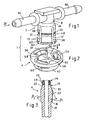
- the connector piece 2 is used to connect at least one media line, not shown, in particular fuel line, to a connector counterpart 6. In addition, is on the FIGS. 5 and 6 directed.
- the connector piece 2 has a plug-in section 8, which can be plugged together with a complementary plug-in section 10 of the connector counterpart 6 media-tight. Further, the connector piece 2 at least two, in particular - as shown - four extending in the insertion direction, radially elastic spring arms 12 which at their free ends latching lugs 14 for latching, kraftformschlüssigen engaging behind a latching step 16 of the connector counterpart 6 in the mated position have (see FIGS. 5 and 6 ).
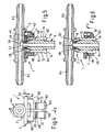
- the fuse element 4 is also in the starting position according to 4 and 5 fixed on the locking means 18.
- the locking means 18 are formed such that a to be applied for movement of the securing element 4 from the starting position to the securing position locking force F1 (see Fig. 4 ) is smaller than a to be applied for the reverse movement of the securing position in the direction of the initial position opening force F2 (see Fig. 6 ). The structural measure for this will be explained in more detail below.
- the securing element 4 with the locking means 18 and the spring arms 12 are formed with their locking lugs 14 in adaptation to the configuration of the connector counterpart 6 such that the fuse element 4 is used as a manual handling attack for plugging (and releasing) the connection in that the plug-in sections 8, 10 can be plugged together into the latched position of the spring arms 12 by manual application of the securing element 4 with an insertion force F acting in the direction of insertion, and only then can the securing element 4 be moved into its securing position.
- the locking means 18 and the spring arms 12 are formed with the locking lugs 14 in adaptation to the connector counterpart 6 so that the movement of the securing element 4 from the starting position to be applied in the securing position closure force F1 greater than that for mating the male sections 8, 10 in their latched step to be applied insertion force F is (see. Fig. 4 ). It is particularly advantageous if the connector piece 2 is formed in the cooperating region of the spring arms 12 and the securing element 4 such that the closure force F1 during the plugging operation temporarily by radial spreading of the spring arms 12 of the Connector piece 2 is increased.
- 12 radially projecting lugs 20 are arranged on the outer circumference of the spring arms, which act as a stop for the fuse element 2 in a slightly spread during the initial insertion operation position of the spring arms 12, so that the fuse element 4 can not be moved into its securing position, but first the connector piece 2 is mated with the connector counterpart 6 until the spring arms 12 engage radially inwardly. Subsequently, then the Sich ceremoniesselment 4 unhindered over the lugs 20 are moved into the securing position.
- the lead connector 1 is specifically designed for a connector mating piece 6 as shown in FIG Fig. 3 . 5 and 6 is shown.
- the plug-in section 10 is designed as a plug-in part 22 (plug shank).
- This plug-in part 22 has at its free end a sealing portion 24 with a seated in an annular groove 26 sealing ring 28.
- Adjoining the sealing section 24 via a conical surface 30 is an area 32 which is widened in cross-section and which merges via the latching step 16 into a tapered region 34 (see in particular FIG Fig. 3 ).
- the conical surface 30 provided in the mating process for the radial spreading of the spring arms 12 of the connector piece 2 includes a relatively shallow angle ⁇ 1 with the plug-in axis, which can lie in particular in the range of approximately 20 °.
- the latching step 16 is designed as a conical inclined surface with a relatively steeper angle ⁇ 2 to the thru-axle of, in particular, about 50 °. From the different angles ⁇ 1 and ⁇ 2 it follows that a release force is greater than an insertion force. This facilitates the attachment and at the same time leads to a high level of security against unwanted loosening.
- the spring arms 12 join in one piece.
- a plurality of, for example, four spring arms 12 are provided in a radially symmetrical circumferential distribution and each separated by axially and radially extending slots 38.
- the securing element 4 is arranged with an annular configuration coaxially and axially displaceable and captive on the connector piece 2.
- the securing element 4 has a circumferentially closed Speringabexcellent 40th in the securing position ( Fig. 6 ), the spring arms 12 in which the radially inwardly facing locking lugs 14 having end portions with only a small radial clearance, that is substantially free of play, encloses.
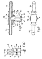
- the locking means 18 consist of at least two, in the illustrated embodiment (see in particular Fig. 2 ) three radially elastic Sich ceremoniessrastarmen 42 of Sich réellesetementes 4 and from latching elements 44 of the Sich réellesrastarme 42 cooperating detent steps 46, 48 of the connector piece 2.
- the locking elements 44 of the Sich réellesrastarme 42 are designed as radially inwardly pointing, nose-like projections, which in the starting position according to 4 and 5 via first locking surfaces 50 (see in particular Fig. 12 ) With a first latching step 46 of the connector piece 2 and in the securing position according to Fig. 6 via second latching surfaces 52 (FIG. Fig. 12 ) cooperate with a second latching step 48 of the connector piece 2.
- first and second latching surfaces 50, 52 of the latching elements 44 of the Sich ceremoniessrastarme 42 are each formed as a cone-like inclined surfaces which include ⁇ 1 and a second acute angle ⁇ 2 with the plug axis a first acute angle, wherein the first angle ⁇ 1 of the first latching surfaces 50 is smaller than the second angle ⁇ 2 of the second locking surfaces 52.
- ⁇ 1 is about 30 °
- ⁇ 2 is about 40 °.
- the locking latching arms 42 connect integrally to the locking ring portion 40 and extend axially in the release direction, ie opposite to the direction of insertion.
- the latching means (Sich mecanicsrastarme 42 with their locking elements 44) are arranged axially offset to the locking portion 40, so that the backup function is separated from the latching function (decoupled).
- the securing element 4 also has a manually operable operating portion 54 which is so independent of the securing latching arms 42 directly connected to the locking portion 40 that a manual operation without affecting the elastic mobility of the Sich mecanicsrastarme 42 is possible.
- the actuating portion 54 with the locking ring portion 40 is integrally connected via in each case arranged in the circumferential direction between the Sichanssrastarmen 42 and spaced slots 56 via connecting webs 58.
- the actuating portion 54 is formed as a circumferentially continuous ring, which encloses the Sich ceremoniessrastarme 42 coaxially with a radial distance (see in particular Fig. 2 and 10 ).
- annular actuating portion 54 in its the securing latching arms 42 each radially opposite peripheral regions via additional web-like connecting portions 60 directly, d. H. independent of the safety latching arms 42 connected to the locking ring portion 40.
- connecting sections 60 stiffening of the ring sections extending freely in the circumferential direction over the regions of the securing latching arms 42 is achieved.
- the above-described lugs 20 of the spring arms 12 are preferably formed as a ring land portions and arranged in the insertion direction immediately before the second latching step 48.
- This latching step 48 is formed as a flank surface of a ringnutförmigen recess 61.
- the spring arms 12 of the connector piece 2 at their free ends radially outwardly projecting lugs 62 have as end stops for the securing element 4 for captive, but still with elastic deformation of the spring arms 12 mountable and removable mount.
- the spring arms 12 have end-side oblique surfaces 63 which cause a required movement of the spring arms 12 radially inwardly when placing the securing element 4.
- the connector piece 2 has, in addition to the plug-in section 8, at least one connecting piece 64 for a media line (hose or pipeline for any hydraulic or pneumatic pressure and / or flow medium, such as fuel).
- a media line hose or pipeline for any hydraulic or pneumatic pressure and / or flow medium, such as fuel
- it is a T-connector with two coaxial, pointing in opposite directions connecting piece 64, of which the plug portion 8 branches off at right angles with the spring arms 12
- the connector piece 2 is preferably formed with its parts described as a one-piece molding made of plastic. The same applies to the securing element 4.
- the connector counterpart 6 may consist of any material, for example of a plastic or metal.
Priority Applications (1)
| Application Number | Priority Date | Filing Date | Title |
|---|---|---|---|
| EP08169594A EP2050996A1 (de) | 2003-12-17 | 2004-11-15 | Steckbarer und verrastbarer Leitungsverbinder |
Applications Claiming Priority (3)
| Application Number | Priority Date | Filing Date | Title |
|---|---|---|---|
| DE20319558U DE20319558U1 (de) | 2003-12-17 | 2003-12-17 | Steckbarer und verrastbarer Leitungsverbinder |
| DE20319558U | 2003-12-17 | ||
| PCT/EP2004/052958 WO2005059426A1 (de) | 2003-12-17 | 2004-11-15 | Steckbarer und verrastbarer leitungsverbinder |
Related Child Applications (1)
| Application Number | Title | Priority Date | Filing Date |
|---|---|---|---|
| EP08169594A Division EP2050996A1 (de) | 2003-12-17 | 2004-11-15 | Steckbarer und verrastbarer Leitungsverbinder |
Publications (3)
| Publication Number | Publication Date |
|---|---|
| EP1567800A1 EP1567800A1 (de) | 2005-08-31 |
| EP1567800B1 EP1567800B1 (de) | 2009-03-25 |
| EP1567800B9 true EP1567800B9 (de) | 2009-09-09 |
Family
ID=34530437
Family Applications (2)
| Application Number | Title | Priority Date | Filing Date |
|---|---|---|---|
| EP08169594A Withdrawn EP2050996A1 (de) | 2003-12-17 | 2004-11-15 | Steckbarer und verrastbarer Leitungsverbinder |
| EP04798203A Active EP1567800B9 (de) | 2003-12-17 | 2004-11-15 | Steckbarer und verrastbarer leitungsverbinder |
Family Applications Before (1)
| Application Number | Title | Priority Date | Filing Date |
|---|---|---|---|
| EP08169594A Withdrawn EP2050996A1 (de) | 2003-12-17 | 2004-11-15 | Steckbarer und verrastbarer Leitungsverbinder |
Country Status (7)
| Country | Link |
|---|---|
| EP (2) | EP2050996A1 (ko) |
| KR (2) | KR100892014B1 (ko) |
| CN (1) | CN1894532B (ko) |
| AT (1) | ATE426772T1 (ko) |
| DE (2) | DE20319558U1 (ko) |
| ES (1) | ES2322856T3 (ko) |
| WO (1) | WO2005059426A1 (ko) |
Families Citing this family (16)
| Publication number | Priority date | Publication date | Assignee | Title |
|---|---|---|---|---|
| DE202005015966U1 (de) * | 2005-10-10 | 2007-02-15 | Voss Automotive Gmbh | Steckverbinder für Medienleitungen |
| EP1890030B1 (fr) * | 2006-08-16 | 2008-09-17 | Delphi Technologies, Inc. | Raccord à accouplement rapide |
| DE202006018697U1 (de) * | 2006-12-11 | 2008-04-10 | Veritas Ag | Leitungsverbindungsvorrichtung |
| FR2928714A1 (fr) | 2008-03-12 | 2009-09-18 | Hutchinson Sa | Dispositif de raccordement pour transfert de fluide,circuit l'incorporant et son procede de montage/demontage. |
| FR2929679B1 (fr) | 2008-04-07 | 2010-04-23 | Raymond A & Cie | Raccord de connecteur pour conduits de fluide avec un ressort en fil metallique |
| CN101961914B (zh) * | 2010-10-21 | 2013-06-19 | 张士生 | 一种吹瓶机的瓶坯输送链 |
| CN101961916A (zh) * | 2010-10-21 | 2011-02-02 | 张士生 | 一种悬挂式瓶坯管弹性插接器 |
| US8550843B2 (en) * | 2010-11-22 | 2013-10-08 | Andrew Llc | Tabbed connector interface |
| DE102011118099A1 (de) * | 2011-11-10 | 2013-05-16 | Illinois Tool Works Inc. | Vorrichtung zum Verbinden zweier Leitungsabschnitte |
| DE102013104597A1 (de) * | 2013-05-06 | 2014-11-06 | Veritas Ag | Fluidstecker |
| CN103967350B (zh) * | 2014-05-12 | 2016-03-30 | 于浩 | 一种插接式锁块 |
| GB2541228B (en) * | 2015-08-13 | 2020-07-15 | Gm Global Tech Operations Llc | Quick fit connector |
| EP3379129B1 (de) * | 2017-03-23 | 2022-09-28 | Georg Fischer JRG AG | Anschlussverbinder |
| CN109099826B (zh) * | 2018-04-18 | 2020-05-08 | 福士汽车零部件(济南)有限公司 | 一种电池热管理管路用快插接头安装状态检具及方法 |
| CN110259783B (zh) * | 2019-06-14 | 2024-03-08 | 安徽富士特铝业有限公司 | 一种铝管及方法 |
| CN110409807B (zh) * | 2019-08-09 | 2021-05-07 | 天津建工城市建设发展有限公司 | 一种屋顶的高支模体系 |
Family Cites Families (7)
| Publication number | Priority date | Publication date | Assignee | Title |
|---|---|---|---|---|
| AU1478176A (en) * | 1975-06-09 | 1977-12-15 | Neta Ind Pty Ltd | Quick release coupling |
| DE2952468A1 (de) | 1979-12-27 | 1981-07-16 | Armaturenfabrik Hermann Voss GmbH + Co, 5272 Wipperfürth | Steckbare verbindungsvorrichtung mit schnappverschluss |
| DE3438173A1 (de) * | 1984-10-18 | 1986-04-24 | Heinrich 5000 Köln Vorschepoth | Kupplungsmuffe zum verbinden von zwei rohrleitungsenden |
| WO1994023775A1 (en) * | 1993-03-23 | 1994-10-27 | Abbott Laboratories | Securing collar for cannula connector |
| CN2361938Y (zh) * | 1999-01-07 | 2000-02-02 | 张和生 | 管道插接装置 |
| JP4242511B2 (ja) * | 1999-05-17 | 2009-03-25 | 株式会社ミクニ | 蒸散バルブのパイプ抜け止め構造 |
| DE10159280B4 (de) * | 2001-12-04 | 2004-12-16 | Kautex Textron Gmbh & Co Kg | Steckverbindung |
-
2003
- 2003-12-17 DE DE20319558U patent/DE20319558U1/de not_active Expired - Lifetime
-
2004
- 2004-11-15 WO PCT/EP2004/052958 patent/WO2005059426A1/de active Application Filing
- 2004-11-15 AT AT04798203T patent/ATE426772T1/de not_active IP Right Cessation
- 2004-11-15 DE DE502004009218T patent/DE502004009218D1/de active Active
- 2004-11-15 CN CN2004800375632A patent/CN1894532B/zh not_active Expired - Fee Related
- 2004-11-15 ES ES04798203T patent/ES2322856T3/es active Active
- 2004-11-15 KR KR1020067013879A patent/KR100892014B1/ko not_active IP Right Cessation
- 2004-11-15 KR KR1020097001343A patent/KR20090024807A/ko not_active Application Discontinuation
- 2004-11-15 EP EP08169594A patent/EP2050996A1/de not_active Withdrawn
- 2004-11-15 EP EP04798203A patent/EP1567800B9/de active Active
Also Published As
| Publication number | Publication date |
|---|---|
| WO2005059426A1 (de) | 2005-06-30 |
| EP1567800B1 (de) | 2009-03-25 |
| CN1894532B (zh) | 2010-07-28 |
| EP1567800A1 (de) | 2005-08-31 |
| ES2322856T3 (es) | 2009-06-30 |
| ATE426772T1 (de) | 2009-04-15 |
| EP2050996A1 (de) | 2009-04-22 |
| DE502004009218D1 (de) | 2009-05-07 |
| KR20090024807A (ko) | 2009-03-09 |
| KR20060126706A (ko) | 2006-12-08 |
| KR100892014B1 (ko) | 2009-04-07 |
| CN1894532A (zh) | 2007-01-10 |
| DE20319558U1 (de) | 2005-04-28 |
Similar Documents
| Publication | Publication Date | Title |
|---|---|---|
| EP1934510B1 (de) | Steckverbinder für medienleitungen | |
| EP1567800B9 (de) | Steckbarer und verrastbarer leitungsverbinder | |
| EP1781979B1 (de) | Steckverbindung für fluid-leitungen | |
| DE10159280B4 (de) | Steckverbindung | |
| EP2542815B1 (de) | Steckverbinder für medienleitungen | |
| EP4127543B1 (de) | Steckverbinder mit vormontagesicherung | |
| EP0860643B1 (de) | Druckmittel-Steckkupplung | |
| EP2479470B1 (de) | Steckkupplung für Druckmittel-Leitungen | |
| EP1264127B1 (de) | Drehbarer absperrhahn für eine steckkupplung mit abgewinkeltem anschlussstutzen | |
| DE202008008421U1 (de) | Steckverbindung für Fluid-Leitungen | |
| EP1731821A2 (de) | Schnellkupplung für ein Rohrsystem | |
| EP1985907A1 (de) | Schnellverschlusskupplung | |
| EP0178626B1 (de) | Kupplungsmuffe zum Verbinden von zwei Rohrleitungsenden | |
| CH690338A5 (de) | Verbindungs- und Anschlussstuck fur Wellrohre. | |
| EP1890069A2 (de) | Steckverbindung | |
| DE102007033696A1 (de) | Steckverbindung | |
| EP1233227B1 (de) | Steckverbindung für Strömungsmittelleitungen | |
| EP1746330A2 (de) | Aufnahmeteil einer Fluid-Steckverbindung | |
| EP0691501A1 (de) | Steckverbinder für Schlauch- und/oder Rohrleitungen | |
| DE102020127867A1 (de) | Fluidverbindungseinheit | |
| EP3081837B1 (de) | Steckverbindung für rohrleitungen | |
| WO2024020611A1 (de) | Steckverbinder zum verbinden von leitungen für flüssige oder gasförmige medien | |
| DE19547312A1 (de) | Lösbare Steckkupplung | |
| DE4444582A1 (de) | Steckverbinder zum Verbinden eines Kunststoffrohres mit einem Anschlußteil | |
| DE102007008965A1 (de) | Kolben für eine Fahrzeug-Luftfeder |
Legal Events
| Date | Code | Title | Description |
|---|---|---|---|
| PUAI | Public reference made under article 153(3) epc to a published international application that has entered the european phase |
Free format text: ORIGINAL CODE: 0009012 |
|
| 17P | Request for examination filed |
Effective date: 20050222 |
|
| AK | Designated contracting states |
Kind code of ref document: A1 Designated state(s): AT BE BG CH CY CZ DE DK EE ES FI FR GB GR HU IE IS IT LI LU MC NL PL PT RO SE SI SK TR |
|
| AX | Request for extension of the european patent |
Extension state: AL HR LT LV MK YU |
|
| DAX | Request for extension of the european patent (deleted) | ||
| GRAP | Despatch of communication of intention to grant a patent |
Free format text: ORIGINAL CODE: EPIDOSNIGR1 |
|
| GRAS | Grant fee paid |
Free format text: ORIGINAL CODE: EPIDOSNIGR3 |
|
| GRAA | (expected) grant |
Free format text: ORIGINAL CODE: 0009210 |
|
| AK | Designated contracting states |
Kind code of ref document: B1 Designated state(s): AT BE BG CH CY CZ DE DK EE ES FI FR GB GR HU IE IS IT LI LU MC NL PL PT RO SE SI SK TR |
|
| REG | Reference to a national code |
Ref country code: GB Ref legal event code: FG4D Free format text: NOT ENGLISH |
|
| REG | Reference to a national code |
Ref country code: CH Ref legal event code: EP |
|
| REG | Reference to a national code |
Ref country code: IE Ref legal event code: FG4D Free format text: LANGUAGE OF EP DOCUMENT: GERMAN |
|
| REF | Corresponds to: |
Ref document number: 502004009218 Country of ref document: DE Date of ref document: 20090507 Kind code of ref document: P |
|
| REG | Reference to a national code |
Ref country code: ES Ref legal event code: FG2A Ref document number: 2322856 Country of ref document: ES Kind code of ref document: T3 |
|
| PG25 | Lapsed in a contracting state [announced via postgrant information from national office to epo] |
Ref country code: SI Free format text: LAPSE BECAUSE OF FAILURE TO SUBMIT A TRANSLATION OF THE DESCRIPTION OR TO PAY THE FEE WITHIN THE PRESCRIBED TIME-LIMIT Effective date: 20090325 Ref country code: FI Free format text: LAPSE BECAUSE OF FAILURE TO SUBMIT A TRANSLATION OF THE DESCRIPTION OR TO PAY THE FEE WITHIN THE PRESCRIBED TIME-LIMIT Effective date: 20090325 |
|
| PG25 | Lapsed in a contracting state [announced via postgrant information from national office to epo] |
Ref country code: PL Free format text: LAPSE BECAUSE OF FAILURE TO SUBMIT A TRANSLATION OF THE DESCRIPTION OR TO PAY THE FEE WITHIN THE PRESCRIBED TIME-LIMIT Effective date: 20090325 Ref country code: SE Free format text: LAPSE BECAUSE OF FAILURE TO SUBMIT A TRANSLATION OF THE DESCRIPTION OR TO PAY THE FEE WITHIN THE PRESCRIBED TIME-LIMIT Effective date: 20090625 |
|
| REG | Reference to a national code |
Ref country code: IE Ref legal event code: FD4D |
|
| PG25 | Lapsed in a contracting state [announced via postgrant information from national office to epo] |
Ref country code: PT Free format text: LAPSE BECAUSE OF FAILURE TO SUBMIT A TRANSLATION OF THE DESCRIPTION OR TO PAY THE FEE WITHIN THE PRESCRIBED TIME-LIMIT Effective date: 20090901 Ref country code: EE Free format text: LAPSE BECAUSE OF FAILURE TO SUBMIT A TRANSLATION OF THE DESCRIPTION OR TO PAY THE FEE WITHIN THE PRESCRIBED TIME-LIMIT Effective date: 20090325 Ref country code: CZ Free format text: LAPSE BECAUSE OF FAILURE TO SUBMIT A TRANSLATION OF THE DESCRIPTION OR TO PAY THE FEE WITHIN THE PRESCRIBED TIME-LIMIT Effective date: 20090325 |
|
| PG25 | Lapsed in a contracting state [announced via postgrant information from national office to epo] |
Ref country code: SK Free format text: LAPSE BECAUSE OF FAILURE TO SUBMIT A TRANSLATION OF THE DESCRIPTION OR TO PAY THE FEE WITHIN THE PRESCRIBED TIME-LIMIT Effective date: 20090325 Ref country code: RO Free format text: LAPSE BECAUSE OF FAILURE TO SUBMIT A TRANSLATION OF THE DESCRIPTION OR TO PAY THE FEE WITHIN THE PRESCRIBED TIME-LIMIT Effective date: 20090325 Ref country code: IS Free format text: LAPSE BECAUSE OF FAILURE TO SUBMIT A TRANSLATION OF THE DESCRIPTION OR TO PAY THE FEE WITHIN THE PRESCRIBED TIME-LIMIT Effective date: 20090725 |
|
| PG25 | Lapsed in a contracting state [announced via postgrant information from national office to epo] |
Ref country code: BG Free format text: LAPSE BECAUSE OF FAILURE TO SUBMIT A TRANSLATION OF THE DESCRIPTION OR TO PAY THE FEE WITHIN THE PRESCRIBED TIME-LIMIT Effective date: 20090625 Ref country code: DK Free format text: LAPSE BECAUSE OF FAILURE TO SUBMIT A TRANSLATION OF THE DESCRIPTION OR TO PAY THE FEE WITHIN THE PRESCRIBED TIME-LIMIT Effective date: 20090325 Ref country code: IE Free format text: LAPSE BECAUSE OF FAILURE TO SUBMIT A TRANSLATION OF THE DESCRIPTION OR TO PAY THE FEE WITHIN THE PRESCRIBED TIME-LIMIT Effective date: 20090325 |
|
| PLBE | No opposition filed within time limit |
Free format text: ORIGINAL CODE: 0009261 |
|
| STAA | Information on the status of an ep patent application or granted ep patent |
Free format text: STATUS: NO OPPOSITION FILED WITHIN TIME LIMIT |
|
| 26N | No opposition filed |
Effective date: 20091229 |
|
| BERE | Be: lapsed |
Owner name: VOSS AUTOMOTIVE G.M.B.H. Effective date: 20091130 |
|
| PG25 | Lapsed in a contracting state [announced via postgrant information from national office to epo] |
Ref country code: MC Free format text: LAPSE BECAUSE OF NON-PAYMENT OF DUE FEES Effective date: 20091130 |
|
| REG | Reference to a national code |
Ref country code: CH Ref legal event code: PL |
|
| GBPC | Gb: european patent ceased through non-payment of renewal fee |
Effective date: 20091115 |
|
| PG25 | Lapsed in a contracting state [announced via postgrant information from national office to epo] |
Ref country code: GR Free format text: LAPSE BECAUSE OF FAILURE TO SUBMIT A TRANSLATION OF THE DESCRIPTION OR TO PAY THE FEE WITHIN THE PRESCRIBED TIME-LIMIT Effective date: 20090626 Ref country code: BE Free format text: LAPSE BECAUSE OF NON-PAYMENT OF DUE FEES Effective date: 20091130 Ref country code: LI Free format text: LAPSE BECAUSE OF NON-PAYMENT OF DUE FEES Effective date: 20091130 Ref country code: CH Free format text: LAPSE BECAUSE OF NON-PAYMENT OF DUE FEES Effective date: 20091130 |
|
| PG25 | Lapsed in a contracting state [announced via postgrant information from national office to epo] |
Ref country code: GB Free format text: LAPSE BECAUSE OF NON-PAYMENT OF DUE FEES Effective date: 20091115 |
|
| PG25 | Lapsed in a contracting state [announced via postgrant information from national office to epo] |
Ref country code: AT Free format text: LAPSE BECAUSE OF NON-PAYMENT OF DUE FEES Effective date: 20091115 |
|
| PG25 | Lapsed in a contracting state [announced via postgrant information from national office to epo] |
Ref country code: IT Free format text: LAPSE BECAUSE OF FAILURE TO SUBMIT A TRANSLATION OF THE DESCRIPTION OR TO PAY THE FEE WITHIN THE PRESCRIBED TIME-LIMIT Effective date: 20090325 |
|
| PG25 | Lapsed in a contracting state [announced via postgrant information from national office to epo] |
Ref country code: LU Free format text: LAPSE BECAUSE OF NON-PAYMENT OF DUE FEES Effective date: 20091115 |
|
| PG25 | Lapsed in a contracting state [announced via postgrant information from national office to epo] |
Ref country code: HU Free format text: LAPSE BECAUSE OF FAILURE TO SUBMIT A TRANSLATION OF THE DESCRIPTION OR TO PAY THE FEE WITHIN THE PRESCRIBED TIME-LIMIT Effective date: 20090926 |
|
| PG25 | Lapsed in a contracting state [announced via postgrant information from national office to epo] |
Ref country code: TR Free format text: LAPSE BECAUSE OF FAILURE TO SUBMIT A TRANSLATION OF THE DESCRIPTION OR TO PAY THE FEE WITHIN THE PRESCRIBED TIME-LIMIT Effective date: 20090325 |
|
| PG25 | Lapsed in a contracting state [announced via postgrant information from national office to epo] |
Ref country code: CY Free format text: LAPSE BECAUSE OF FAILURE TO SUBMIT A TRANSLATION OF THE DESCRIPTION OR TO PAY THE FEE WITHIN THE PRESCRIBED TIME-LIMIT Effective date: 20090325 |
|
| PGFP | Annual fee paid to national office [announced via postgrant information from national office to epo] |
Ref country code: FR Payment date: 20131108 Year of fee payment: 10 |
|
| PGFP | Annual fee paid to national office [announced via postgrant information from national office to epo] |
Ref country code: ES Payment date: 20131029 Year of fee payment: 10 |
|
| REG | Reference to a national code |
Ref country code: FR Ref legal event code: ST Effective date: 20150731 |
|
| PG25 | Lapsed in a contracting state [announced via postgrant information from national office to epo] |
Ref country code: FR Free format text: LAPSE BECAUSE OF NON-PAYMENT OF DUE FEES Effective date: 20141201 |
|
| REG | Reference to a national code |
Ref country code: ES Ref legal event code: FD2A Effective date: 20160105 |
|
| PG25 | Lapsed in a contracting state [announced via postgrant information from national office to epo] |
Ref country code: ES Free format text: LAPSE BECAUSE OF NON-PAYMENT OF DUE FEES Effective date: 20141116 |
|
| PGFP | Annual fee paid to national office [announced via postgrant information from national office to epo] |
Ref country code: NL Payment date: 20171129 Year of fee payment: 14 |
|
| REG | Reference to a national code |
Ref country code: NL Ref legal event code: MM Effective date: 20181201 |
|
| PG25 | Lapsed in a contracting state [announced via postgrant information from national office to epo] |
Ref country code: NL Free format text: LAPSE BECAUSE OF NON-PAYMENT OF DUE FEES Effective date: 20181201 |
|
| PGFP | Annual fee paid to national office [announced via postgrant information from national office to epo] |
Ref country code: DE Payment date: 20230126 Year of fee payment: 19 |