EP1567800B9 - Pluggable and lockable line connector - Google Patents
Pluggable and lockable line connector Download PDFInfo
- Publication number
- EP1567800B9 EP1567800B9 EP04798203A EP04798203A EP1567800B9 EP 1567800 B9 EP1567800 B9 EP 1567800B9 EP 04798203 A EP04798203 A EP 04798203A EP 04798203 A EP04798203 A EP 04798203A EP 1567800 B9 EP1567800 B9 EP 1567800B9
- Authority
- EP
- European Patent Office
- Prior art keywords
- latch
- securing
- piece
- connector according
- securing element
- Prior art date
- Legal status (The legal status is an assumption and is not a legal conclusion. Google has not performed a legal analysis and makes no representation as to the accuracy of the status listed.)
- Active
Links
Images

Classifications
-
- F—MECHANICAL ENGINEERING; LIGHTING; HEATING; WEAPONS; BLASTING
- F16—ENGINEERING ELEMENTS AND UNITS; GENERAL MEASURES FOR PRODUCING AND MAINTAINING EFFECTIVE FUNCTIONING OF MACHINES OR INSTALLATIONS; THERMAL INSULATION IN GENERAL
- F16L—PIPES; JOINTS OR FITTINGS FOR PIPES; SUPPORTS FOR PIPES, CABLES OR PROTECTIVE TUBING; MEANS FOR THERMAL INSULATION IN GENERAL
- F16L37/00—Couplings of the quick-acting type
- F16L37/08—Couplings of the quick-acting type in which the connection between abutting or axially overlapping ends is maintained by locking members
- F16L37/12—Couplings of the quick-acting type in which the connection between abutting or axially overlapping ends is maintained by locking members using hooks, pawls or other movable or insertable locking members
- F16L37/133—Couplings of the quick-acting type in which the connection between abutting or axially overlapping ends is maintained by locking members using hooks, pawls or other movable or insertable locking members using flexible hooks
-
- F—MECHANICAL ENGINEERING; LIGHTING; HEATING; WEAPONS; BLASTING
- F02—COMBUSTION ENGINES; HOT-GAS OR COMBUSTION-PRODUCT ENGINE PLANTS
- F02M—SUPPLYING COMBUSTION ENGINES IN GENERAL WITH COMBUSTIBLE MIXTURES OR CONSTITUENTS THEREOF
- F02M37/00—Apparatus or systems for feeding liquid fuel from storage containers to carburettors or fuel-injection apparatus; Arrangements for purifying liquid fuel specially adapted for, or arranged on, internal-combustion engines
- F02M37/0011—Constructional details; Manufacturing or assembly of elements of fuel systems; Materials therefor
- F02M37/0017—Constructional details; Manufacturing or assembly of elements of fuel systems; Materials therefor related to fuel pipes or their connections, e.g. joints or sealings
-
- F—MECHANICAL ENGINEERING; LIGHTING; HEATING; WEAPONS; BLASTING
- F02—COMBUSTION ENGINES; HOT-GAS OR COMBUSTION-PRODUCT ENGINE PLANTS
- F02M—SUPPLYING COMBUSTION ENGINES IN GENERAL WITH COMBUSTIBLE MIXTURES OR CONSTITUENTS THEREOF
- F02M55/00—Fuel-injection apparatus characterised by their fuel conduits or their venting means; Arrangements of conduits between fuel tank and pump F02M37/00
- F02M55/002—Arrangement of leakage or drain conduits in or from injectors
-
- F—MECHANICAL ENGINEERING; LIGHTING; HEATING; WEAPONS; BLASTING
- F02—COMBUSTION ENGINES; HOT-GAS OR COMBUSTION-PRODUCT ENGINE PLANTS
- F02M—SUPPLYING COMBUSTION ENGINES IN GENERAL WITH COMBUSTIBLE MIXTURES OR CONSTITUENTS THEREOF
- F02M55/00—Fuel-injection apparatus characterised by their fuel conduits or their venting means; Arrangements of conduits between fuel tank and pump F02M37/00
- F02M55/004—Joints; Sealings
-
- F—MECHANICAL ENGINEERING; LIGHTING; HEATING; WEAPONS; BLASTING
- F16—ENGINEERING ELEMENTS AND UNITS; GENERAL MEASURES FOR PRODUCING AND MAINTAINING EFFECTIVE FUNCTIONING OF MACHINES OR INSTALLATIONS; THERMAL INSULATION IN GENERAL
- F16L—PIPES; JOINTS OR FITTINGS FOR PIPES; SUPPORTS FOR PIPES, CABLES OR PROTECTIVE TUBING; MEANS FOR THERMAL INSULATION IN GENERAL
- F16L37/00—Couplings of the quick-acting type
- F16L37/08—Couplings of the quick-acting type in which the connection between abutting or axially overlapping ends is maintained by locking members
- F16L37/12—Couplings of the quick-acting type in which the connection between abutting or axially overlapping ends is maintained by locking members using hooks, pawls or other movable or insertable locking members
- F16L37/138—Couplings of the quick-acting type in which the connection between abutting or axially overlapping ends is maintained by locking members using hooks, pawls or other movable or insertable locking members using an axially movable sleeve
-
- F—MECHANICAL ENGINEERING; LIGHTING; HEATING; WEAPONS; BLASTING
- F02—COMBUSTION ENGINES; HOT-GAS OR COMBUSTION-PRODUCT ENGINE PLANTS
- F02M—SUPPLYING COMBUSTION ENGINES IN GENERAL WITH COMBUSTIBLE MIXTURES OR CONSTITUENTS THEREOF
- F02M2200/00—Details of fuel-injection apparatus, not otherwise provided for
- F02M2200/85—Mounting of fuel injection apparatus
- F02M2200/853—Mounting of fuel injection apparatus involving use of quick-acting mechanism, e.g. clips
Definitions
- the present invention relates to a pluggable and latchable line connector with a connector piece for connecting at least one media line, in particular fuel line, to a connector counterpart, according to the preamble of claim 1.
- a cannula connector which is basically to be designated as a line connector in the sense of the preamble of claim 1.
- a securing element in the form of a circumferentially closed locking ring is provided which is slidably mounted on spring arms (segments).
- the spring arms on a central transition portion in the form of an outer, radially outwardly projecting Wulstansatzes.
- the locking ring interacts with this approach so detent that it is fixed in two positions each of these locking means.
- the locking ring has a certain inner diameter, with which it must be moved over the approach each, the locking function should not be optimal, or in this area is likely to occur a rapid wear in such a way that wear of the approach the locking function quite quickly should be affected.
- Another line connector is for example in the DE 29 52 468 A1 described.
- the connector piece to be connected to a pipeline with its plug-in section designed as a plug shank can be inserted into a bore of the plug-in section of the connector counterpart.
- the connector piece with spring arms engages over a provided with an outer annular bead collar of the connector counterpart.
- a retaining sleeve from behind over the spring arms can be pushed as a fuse element.
- An axial securing of this retaining sleeve takes place by means formed on the outside of the spring arms Schnappwülste which engage in an annular groove in the inside of the retaining sleeve when the retaining sleeve is in its end position (securing position).
- the latching thus takes place in the free end region of the spring arms with a circumferentially closed, continuous sleeve portion of the retaining sleeve, which makes handling difficult.
- the present invention has for its object to improve a line connector of the type mentioned in terms of its safety against accidental release of the connector and also with respect to its handling.
- the fuse element is thus designed such that a separation of its fuse function and its latching function is achieved.
- a closed locking ring section and a plurality of radially elastic locking strut arms are provided in an axially offset arrangement.
- the securing element is fixed in the starting position on the locking means, wherein the locking means are formed such that a to be applied for movement of the securing element from the starting position in the Sicheningswolf closure force is smaller than one for the reverse movement of the securing position in the direction the initial position applied opening force.
- the securing element with the locking means and the spring arms are formed with their locking lugs in adaptation to the connector counterpart such that the fuse element is used as a manual handling attack for inserting the connection, wherein by manual loading (only) of the fuse element with a plug-in force acting in the plug-in direction, the plug-in sections can first be put together into the latched position of the spring arms, and only then can the securing element be moved into the securing position.
- the securing element can also serve as a handle for releasing, by the securing element is moved back to its initial position by manual loading with a release force, and then the connector piece is taken over a movement stop and separated from the connector counterpart.
- the latching means and the spring arms are formed with the locking lugs in adaptation to the connector counterpart so that the movement of the securing element from the starting position to be applied in the locking position locking force greater than that for mating the male sections to their latched position applied insertion force.
- the connector piece in the cooperating region of the spring arms and the securing element is designed such that the closure force is temporarily increased during the plugging operation by radially spreading the spring arms of the connector piece, wherein preferably radially projecting lugs are arranged on the outer periphery of the spring arms.
- the connector piece 2 is used to connect at least one media line, not shown, in particular fuel line, to a connector counterpart 6. In addition, is on the FIGS. 5 and 6 directed.
- the connector piece 2 has a plug-in section 8, which can be plugged together with a complementary plug-in section 10 of the connector counterpart 6 media-tight. Further, the connector piece 2 at least two, in particular - as shown - four extending in the insertion direction, radially elastic spring arms 12 which at their free ends latching lugs 14 for latching, kraftformschlüssigen engaging behind a latching step 16 of the connector counterpart 6 in the mated position have (see FIGS. 5 and 6 ).
- the fuse element 4 is also in the starting position according to 4 and 5 fixed on the locking means 18.
- the locking means 18 are formed such that a to be applied for movement of the securing element 4 from the starting position to the securing position locking force F1 (see Fig. 4 ) is smaller than a to be applied for the reverse movement of the securing position in the direction of the initial position opening force F2 (see Fig. 6 ). The structural measure for this will be explained in more detail below.
- the securing element 4 with the locking means 18 and the spring arms 12 are formed with their locking lugs 14 in adaptation to the configuration of the connector counterpart 6 such that the fuse element 4 is used as a manual handling attack for plugging (and releasing) the connection in that the plug-in sections 8, 10 can be plugged together into the latched position of the spring arms 12 by manual application of the securing element 4 with an insertion force F acting in the direction of insertion, and only then can the securing element 4 be moved into its securing position.
- the locking means 18 and the spring arms 12 are formed with the locking lugs 14 in adaptation to the connector counterpart 6 so that the movement of the securing element 4 from the starting position to be applied in the securing position closure force F1 greater than that for mating the male sections 8, 10 in their latched step to be applied insertion force F is (see. Fig. 4 ). It is particularly advantageous if the connector piece 2 is formed in the cooperating region of the spring arms 12 and the securing element 4 such that the closure force F1 during the plugging operation temporarily by radial spreading of the spring arms 12 of the Connector piece 2 is increased.
- 12 radially projecting lugs 20 are arranged on the outer circumference of the spring arms, which act as a stop for the fuse element 2 in a slightly spread during the initial insertion operation position of the spring arms 12, so that the fuse element 4 can not be moved into its securing position, but first the connector piece 2 is mated with the connector counterpart 6 until the spring arms 12 engage radially inwardly. Subsequently, then the Sich ceremoniesselment 4 unhindered over the lugs 20 are moved into the securing position.
- the lead connector 1 is specifically designed for a connector mating piece 6 as shown in FIG Fig. 3 . 5 and 6 is shown.
- the plug-in section 10 is designed as a plug-in part 22 (plug shank).
- This plug-in part 22 has at its free end a sealing portion 24 with a seated in an annular groove 26 sealing ring 28.
- Adjoining the sealing section 24 via a conical surface 30 is an area 32 which is widened in cross-section and which merges via the latching step 16 into a tapered region 34 (see in particular FIG Fig. 3 ).
- the conical surface 30 provided in the mating process for the radial spreading of the spring arms 12 of the connector piece 2 includes a relatively shallow angle ⁇ 1 with the plug-in axis, which can lie in particular in the range of approximately 20 °.
- the latching step 16 is designed as a conical inclined surface with a relatively steeper angle ⁇ 2 to the thru-axle of, in particular, about 50 °. From the different angles ⁇ 1 and ⁇ 2 it follows that a release force is greater than an insertion force. This facilitates the attachment and at the same time leads to a high level of security against unwanted loosening.
- the spring arms 12 join in one piece.
- a plurality of, for example, four spring arms 12 are provided in a radially symmetrical circumferential distribution and each separated by axially and radially extending slots 38.
- the securing element 4 is arranged with an annular configuration coaxially and axially displaceable and captive on the connector piece 2.
- the securing element 4 has a circumferentially closed Speringabexcellent 40th in the securing position ( Fig. 6 ), the spring arms 12 in which the radially inwardly facing locking lugs 14 having end portions with only a small radial clearance, that is substantially free of play, encloses.
- the locking means 18 consist of at least two, in the illustrated embodiment (see in particular Fig. 2 ) three radially elastic Sich ceremoniessrastarmen 42 of Sich réellesetementes 4 and from latching elements 44 of the Sich réellesrastarme 42 cooperating detent steps 46, 48 of the connector piece 2.
- the locking elements 44 of the Sich réellesrastarme 42 are designed as radially inwardly pointing, nose-like projections, which in the starting position according to 4 and 5 via first locking surfaces 50 (see in particular Fig. 12 ) With a first latching step 46 of the connector piece 2 and in the securing position according to Fig. 6 via second latching surfaces 52 (FIG. Fig. 12 ) cooperate with a second latching step 48 of the connector piece 2.
- first and second latching surfaces 50, 52 of the latching elements 44 of the Sich ceremoniessrastarme 42 are each formed as a cone-like inclined surfaces which include ⁇ 1 and a second acute angle ⁇ 2 with the plug axis a first acute angle, wherein the first angle ⁇ 1 of the first latching surfaces 50 is smaller than the second angle ⁇ 2 of the second locking surfaces 52.
- ⁇ 1 is about 30 °
- ⁇ 2 is about 40 °.
- the locking latching arms 42 connect integrally to the locking ring portion 40 and extend axially in the release direction, ie opposite to the direction of insertion.
- the latching means (Sich mecanicsrastarme 42 with their locking elements 44) are arranged axially offset to the locking portion 40, so that the backup function is separated from the latching function (decoupled).
- the securing element 4 also has a manually operable operating portion 54 which is so independent of the securing latching arms 42 directly connected to the locking portion 40 that a manual operation without affecting the elastic mobility of the Sich mecanicsrastarme 42 is possible.
- the actuating portion 54 with the locking ring portion 40 is integrally connected via in each case arranged in the circumferential direction between the Sichanssrastarmen 42 and spaced slots 56 via connecting webs 58.
- the actuating portion 54 is formed as a circumferentially continuous ring, which encloses the Sich ceremoniessrastarme 42 coaxially with a radial distance (see in particular Fig. 2 and 10 ).
- annular actuating portion 54 in its the securing latching arms 42 each radially opposite peripheral regions via additional web-like connecting portions 60 directly, d. H. independent of the safety latching arms 42 connected to the locking ring portion 40.
- connecting sections 60 stiffening of the ring sections extending freely in the circumferential direction over the regions of the securing latching arms 42 is achieved.
- the above-described lugs 20 of the spring arms 12 are preferably formed as a ring land portions and arranged in the insertion direction immediately before the second latching step 48.
- This latching step 48 is formed as a flank surface of a ringnutförmigen recess 61.
- the spring arms 12 of the connector piece 2 at their free ends radially outwardly projecting lugs 62 have as end stops for the securing element 4 for captive, but still with elastic deformation of the spring arms 12 mountable and removable mount.
- the spring arms 12 have end-side oblique surfaces 63 which cause a required movement of the spring arms 12 radially inwardly when placing the securing element 4.
- the connector piece 2 has, in addition to the plug-in section 8, at least one connecting piece 64 for a media line (hose or pipeline for any hydraulic or pneumatic pressure and / or flow medium, such as fuel).
- a media line hose or pipeline for any hydraulic or pneumatic pressure and / or flow medium, such as fuel
- it is a T-connector with two coaxial, pointing in opposite directions connecting piece 64, of which the plug portion 8 branches off at right angles with the spring arms 12
- the connector piece 2 is preferably formed with its parts described as a one-piece molding made of plastic. The same applies to the securing element 4.
- the connector counterpart 6 may consist of any material, for example of a plastic or metal.
Abstract
Description
Die vorliegende Erfindung betrifft einen steckbaren und verrastbaren Leitungsverbinder mit einem Verbinderstück zum Anschluß mindestens einer Medienleitung, insbesondere Kraftstoffleitung, an ein Verbindergegenstück, nach dem Oberbegriff des Anspruchs 1.The present invention relates to a pluggable and latchable line connector with a connector piece for connecting at least one media line, in particular fuel line, to a connector counterpart, according to the preamble of
Das Dokument
Ein weiterer Leitungsverbinder ist beispielsweise in der
Der vorliegenden Erfindung liegt die Aufgabe zugrunde, einen Leitungsverbinder der genannten Art bezüglich seiner Sicherheit gegen ungewolltes Lösen der Steckverbindung sowie auch bezüglich seiner Handhabung zu verbessern.The present invention has for its object to improve a line connector of the type mentioned in terms of its safety against accidental release of the connector and also with respect to its handling.
Erfindungsgemäß wird dies durch die Merkmale des Anspruchs 1 erreicht.This is achieved by the features of
Erfindungsgemäß ist demnach das Sicherungselement derart ausgebildet, dass eine Trennung seiner Sicherungsfunktion und seiner Rastfunktion erreicht wird. Konstruktiv sind dazu ein geschlossener Sperrringabschnitt und mehrere radialelastische Sicherungstastarme in einer axial versetzten Anordnung vorgesehen. Durch diese Funktionstrennung wird eine sichere Arretierung der Federarme des Verbinderstückes erreicht, indem der Sperrringabschnitt die Federarme mit geringem Spiel umschließt, und die Rastung kann unabhängig davon so ausgelegt sein, dass eine gute Handhabung beim Betätigen des Sicherungselementes erreicht wird.According to the invention, the fuse element is thus designed such that a separation of its fuse function and its latching function is achieved. Structurally, a closed locking ring section and a plurality of radially elastic locking strut arms are provided in an axially offset arrangement. By this separation of functions, a secure locking of the spring arms of the connector piece is achieved by the locking ring portion enclosing the spring arms with little play, and the detent can be independently designed so that a good handling when operating the securing element is achieved.
In berorzugter Ausgestallung der Erfindung ist das Sicherungselement auch in der Ausgangsstellung über die Rastmittel fixiert, wobei die Rastmittel derart ausgebildet sind, dass eine zur Bewegung des Sicherungselementes aus der Ausgangsstellung in die Sicheningsstellung aufzubringende Verschlußkraft kleiner ist als eine zur umgekehrten Bewegung aus der Sicherungsstellung in Richtung der Ausgangsstellung aufzubringende Öffnungskraft.In berorzugter Ausgestallung of the invention, the securing element is fixed in the starting position on the locking means, wherein the locking means are formed such that a to be applied for movement of the securing element from the starting position in the Sicheningsstellung closure force is smaller than one for the reverse movement of the securing position in the direction the initial position applied opening force.
Durch die höhere Öffnungskraft wird eine erhöhte Sicherheit gegen ungewolltes Lösen erreicht, und die relativ geringere Verschlußkraft trägt zu einer einfachen Handhabung beim Steckvorgang bei.Due to the higher opening force increased security against unwanted loosening is achieved, and the relatively lower closure force contributes to ease of handling during mating.
Zusätzlich dazu kann vorgesehen sein, dass das Sicherungselement mit den Rastmitteln sowie die Federarme mit ihren Rastansätzen in Anpassung an das Verbindergegenstück derart ausgebildet sind, dass das Sicherungselement als manueller Handhabungsangriff zum Stecken der Verbindung verwendbar ist, wobei durch manuelle Beaufschlagung (nur) des Sicherungselementes mit einer in Steckrichtung wirkenden Steckkraft zuerst die Steckabschnitte bis in die verrastete Stellung der Federarme zusammensteckbar sind und erst dann das Sicherungselement bis in die Sicherungsstellung bewegbar ist. Durch diese vorteilhafte Ausgestaltung ist es möglich, die Steckverbindung allein durch Ergreifen des Sicherungselementes zu stecken. Umgekehrt kann das Sicherungselement auch als Handhabe zum Lösen dienen, indem durch manuelle Beaufschlagung mit einer Lösekraft das Sicherungselement erst in Richtung seiner Ausgangsstellung zurückbewegt wird, und anschließend wird über einen Bewegungsanschlag das Verbinderstück mitgenommen und von dem Verbindergegenstück getrennt.In addition, it can be provided that the securing element with the locking means and the spring arms are formed with their locking lugs in adaptation to the connector counterpart such that the fuse element is used as a manual handling attack for inserting the connection, wherein by manual loading (only) of the fuse element with a plug-in force acting in the plug-in direction, the plug-in sections can first be put together into the latched position of the spring arms, and only then can the securing element be moved into the securing position. This advantageous embodiment, it is possible to plug the connector alone by gripping the fuse element. Conversely, the securing element can also serve as a handle for releasing, by the securing element is moved back to its initial position by manual loading with a release force, and then the connector piece is taken over a movement stop and separated from the connector counterpart.
Diese Ausgestaltung führt zu einer einfachen und komfortablen Handhabung beim Stecken und Lösen. Dazu ist es zudem vorteilhaft, wenn die Rastmittel und die Federarme mit den Rastansätzen in Anpassung an das Verbindergegenstück so ausgebildet sind, dass die zur Bewegung des Sicherungselementes aus der Ausgangsstellung in die Sicherungsstellung aufzubringende Verschlußkraft größer als die zum Zusammenstecken der Steckabschnitte bis in ihre verrastete Stellung aufzubringende Steckkraft ist. In weiterer vorteilhafter Ausgestaltung ist dazu das Verbinderstück im zusammenwirkenden Bereich der Federarme und des Sicherungselementes derart ausgebildet, dass die Verschlußkraft während des Steckvorgangs zeitweise durch radiales Spreizen der Federarme des Verbinderstückes erhöht wird, wobei vorzugsweise am äußeren Umfang der Federarme radial vorstehende Ansätze angeordnet sind. Diese Ansätze wirken in einer leicht gespreizten Stellung der Federarme als Anschläge für das Sicherungselement. Die Ansätze weisen aber eine radial derart geringe Höhe auf, dass nach dem Verrasten der Federarme das Sicherungselement ungehindert über die Ansätze hinaus weiter in die Sicherungsstellung bewegbar ist.This configuration leads to a simple and comfortable handling when plugging and loosening. For this purpose, it is also advantageous if the latching means and the spring arms are formed with the locking lugs in adaptation to the connector counterpart so that the movement of the securing element from the starting position to be applied in the locking position locking force greater than that for mating the male sections to their latched position applied insertion force. In a further advantageous embodiment, the connector piece in the cooperating region of the spring arms and the securing element is designed such that the closure force is temporarily increased during the plugging operation by radially spreading the spring arms of the connector piece, wherein preferably radially projecting lugs are arranged on the outer periphery of the spring arms. These approaches act in a slightly spread position of the spring arms as stops for the fuse element. However, the lugs have a radially so small height that after locking the spring arms, the securing element unhindered beyond the lugs further into the securing position is movable.
Weitere vorteilhafte Ausgestaltungsmerkmale der Erfindung sind in den abhängigen Ansprüchen sowie der folgenden Beschreibung enthalten.Further advantageous features of the invention are contained in the dependent claims and the following description.
Anhand eines in der Zeichnung veranschaulichten, bevorzugten Ausführungsbeispiels soll die Erfindung genauer erläutert werden. Dabei zeigen:
-
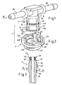
Fig. 1 eine Perspektivansicht eines Verbinderstückes eines erfindungsgemäßen Leitungsverbinders, -
Fig. 2 eine gesonderte Perspektivansicht eines Sicherungselementes des erfindungsgemäßen Leitungsverbinders in einer zu dem Verbinderstück gemäßFig. 1 zum Aufsetzen lagerichtigen Anordnung, -
Fig. 3 eine Längsschnittansicht eines Verbindergegenstückes, -
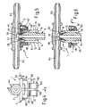
Fig. 4 eine Seitenansicht in Pfeilrichtung IV gemäßFig. 1 auf das Verbinderstück mit aufgesetztem und in einer Ausgangsstellung angeordnetem Sicherungselement, -
Fig. 5 einen Schnitt in der Ebene V - V gemäßFig. 4 mit zusätzlich eingezeichnetem Verbindergegenstück in der zusammengesteckten und verrasteten, jedoch noch nicht durch das Sicherungselement gesicherten Position, -
Fig. 6 eine Darstellung analog zuFig. 5 , jedoch in der Sicherungsstellung des Sicherungselementes, -
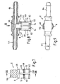
Fig. 7 eine Ansicht analog zuFig. 4 nur des Verbinderstückes ohne Sicherungselement, -
Fig. 8 einen Schnitt analog zuFig. 5 in der Ebene VIII - VIII gemäßFig. 7 , -
Fig. 9 eine Draufsicht auf das Verbinderstück in Pfeilrichtung IX gemäßFig. 8 , -
Fig. 10 eine Draufsicht des Sicherungselementes in Pfeilrichtung X gemäßFig. 2 , -
Fig. 11 einen Schnitt durch das Sicherungselement in der Ebene XI - XI gemäßFig. 10 und -
Fig. 12 eine Ausschnittvergrößerung im Bereich XII gemäßFig. 11 zur Erläuterung der Geometrie im Bereich der Rastmittel des Sicherungselementes.
-
Fig. 1 a perspective view of a connector piece of a line connector according to the invention, -
Fig. 2 a separate perspective view of a fuse element of the line connector according to the invention in a to the connector piece according toFig. 1 for placing in the correct position arrangement, -
Fig. 3 a longitudinal sectional view of a connector counterpart, -
Fig. 4 a side view in the direction of arrow IV according toFig. 1 on the connector piece with an attached and arranged in a starting position fuse element, -
Fig. 5 a section in the plane V - V according toFig. 4 with additional drawn connector counterpart in the mated and latched, but not yet secured by the securing element position, -
Fig. 6 a representation analogous toFig. 5 but in the securing position of the securing element, -
Fig. 7 a view analogous toFig. 4 only the connector piece without fuse element, -
Fig. 8 a section analogous toFig. 5 in level VIII - VIII according toFig. 7 . -
Fig. 9 a plan view of the connector piece in the direction of arrow IX according toFig. 8 . -
Fig. 10 a plan view of the fuse element in the direction of arrow X according toFig. 2 . -
Fig. 11 a section through the fuse element in the plane XI - XI according toFig. 10 and -
Fig. 12 a section enlargement in the area XII according toFig. 11 to explain the geometry in the region of the locking means of the securing element.
In den verschiedenen Figuren der Zeichnung sind gleiche Teile stets mit den gleichen Bezugszeichen versehen und brauchen daher in der Regel auch jeweils nur einmal beschrieben zu werden.In the various figures of the drawing, the same parts are always provided with the same reference numerals and therefore usually need to be described only once in each case.
Wie sich zunächst aus
Das Verbinderstück 2 weist einen Steckabschnitt 8 auf, der mit einem komplementären Steckabschnitt 10 des Verbindergegenstückes 6 mediendicht zusammensteckbar ist. Ferner weist das Verbinderstück 2 mindestens zwei, insbesondere - wie dargestellt - vier sich in Steckrichtung erstreckende, radial elastische Federarme 12 auf, die an ihren freien Enden Rastansätze 14 zum rastenden, kraftformschlüssigen Hintergreifen einer Raststufe 16 des Verbindergegenstückes 6 in der zusammengesteckten Stellung aufweisen (vergleiche
Wie sich weiter insbesondere aus
Zweckmäßig ist das Sicherungselement 4 auch in der Ausgangsstellung gemäß
Es ist weiterhin vorteilhaft, wenn das Sicherungselement 4 mit den Rastmitteln 18 sowie die Federarme 12 mit ihren Rastansätzen 14 in Anpassung an die Ausgestaltung des Verbindergegenstückes 6 derart ausgebildet sind, dass das Sicherungselement 4 als manueller Handhabungsangriff zum Stecken (und Lösen) der Verbindung verwendbar ist, indem durch manuelle Beaufschlagung des Sicherungselementes 4 mit einer in Steckrichtung wirkenden Steckkraft F zuerst die Steckabschnitte 8, 10 bis in die verrastete Stellung der Federarme 12 zusammensteckbar sind und erst dann das Sicherungselement 4 bis in seine Sicherungsstellung bewegbar ist. Dazu sind die Rastmittel 18 und die Federarme 12 mit den Rastansätzen 14 in Anpassung an das Verbindergegenstück 6 so ausgebildet, dass die zur Bewegung des Sicherungselementes 4 aus der Ausgangsstellung in die Sicherungsstellung aufzubringende Verschlußkraft F1 größer als die zum Zusammenstecken der Steckabschnitte 8, 10 bis in ihre verrastete Steilung aufzubringende Steckkraft F ist (vgl.
In der dargestellten, bevorzugten Ausführungsform ist der Leitungsverbinder 1 speziell für ein Verbindergegenstück 6 konzipiert, wie es in
Aufgrund der beschriebenen Ausgestaltung des Verbindergegenstückes 6 ist der Steckabschnitt 8 des Verbinderstückes 2 als entsprechend muffenartige Aufnahme 36 für das Einsteckteil 22 des Verbindergegenstückes 6 ausgebildet. An den Steckabschnitt 8 bzw. die Aufnahme 36 schließen sich die Federarme 12 einstückig an. Bevorzugt sind mehrere, beispielsweise vier Federarme 12 in einer radialsymmetrischen Umfangsverteilung und jeweils über axial und radial durchgehende Schlitze 38 voneinander getrennt vorgesehen.Due to the described configuration of the
Das Sicherungselement 4 ist mit einer ringförmigen Ausgestaltung koaxial und axial verschiebbar sowie unverlierbar auf dem Verbinderstück 2 angeordnet. Dabei weist das Sicherungselement 4 einen in Umfangsrichtung geschlossen Speringabschnitt 40 auf, der in der Sicherungsstellung (
Die Rastmittel 18 bestehen aus mindestens zwei, im dargestellten Ausführungsbeispiel (siehe dazu insbesondere
In einer weiteren bevorzugten Ausgestaltung ist der ringförmige Betätigungsabschnitt 54 in seinen den Sicherungsrastarmen 42 jeweils radial gegenüberliegenden Umfangsbereichen über zusätzliche stegartige Verbindungsabschnitte 60 direkt, d. h. von den Sicherungsrastarmen 42 unabhängig, mit dem Sperrringabschnitt 40 verbunden. Durch diese Verbindungsabschnitte 60 wird eine Versteifung der sich jeweils in Umfangsrichtung frei über die Bereiche der Sicherungsrastarme 42 erstreckenden Ringabschnitte erreicht.In a further preferred embodiment, the
Die oben beschriebenen Ansätze 20 der Federarme 12 sind bevorzugt als Ringstegabschnitte ausgebildet und in Steckrichtung gesehen unmittelbar vor der zweiten Raststufe 48 angeordnet. Diese Raststufe 48 ist als eine Flankenfläche einer ringnutförmigen Vertiefung 61 gebildet.The above-described
Es ist weiterhin zweckmäßig, wenn die Federarme 12 des Verbinderstückes 2 an ihren freien Enden radial nach außen vorstehende Ansätze 62 als Endanschläge für das Sicherungselement 4 zur unverlierbaren, aber dennoch unter elastischer Verformung der Federarme 12 montierbaren und demontierbaren Halterung aufweisen. Für die Montage des Sicherungselementes 4 durch axiales Aufsetzen ist es vorteilhaft, wenn die Federarme 12 endseitige Schrägflächen 63 aufweisen, die beim Aufsetzen des Sicherungselementes 4 eine dazu erforderliche Bewegung der Federarme 12 radial nach innen bewirken.It is also expedient if the
Das Verbinderstück 2 weist im Übrigen im Anschluß an den Steckabschnitt 8 mindestens einen Anschlußstutzen 64 für eine Medienleitung (Schlauch- oder Rohrleitung für ein beliebiges hydraulisches oder pneumatisches Druck- und/oder Strömungsmedium, wie z. B. Kraftstoff) auf. Bei der dargestellten Ausführungsform handelt es sich um einen T-Verbinder mit zwei koaxialen, in entgegengesetze Richtungen weisenden Anschlußstutzen 64, von denen der Steckabschnitt 8 mit den Federarmen 12 rechtwinklig abzweigt Es ist jedoch auch eine Ausführung mit nur einem Anschlußstutzen 64 möglich, beispielsweise als Winkelverbinder mit einem bestimmten Winkel von z. B. 90° zwischen Steckabschnitt und Anschlußstutzen oder mit einem koaxial in die der Steckrichtung entgegengesetzte Richtung weisenden Anschlußstutzen.Incidentally, the
Das Verbinderstück 2 ist mit seinen beschriebenen Teilen bevorzugt als einstückiges Formteil aus Kunststoff ausgebildet. Entsprechendes gilt auch für das Sicherungselement 4. Das Verbindergegenstück 6 kann aus einem beliebigen Material bestehen, beispielsweise aus einem Kunststoff oder Metall.The
Claims (21)
- A plug-in and latchable line connector (1) for connecting at least one media line, in particular fuel line, to a connector counter-piece (6), consisting of a connector piece (2) with a connection section (8), which can be assembled in a media-tight manner with a complementary connection section (10) of the connector counter-piece (6), and with at least one, in particular at least two, radially elastic spring arms (12) extending in the direction of connection, which have at their free ends latch projections (14) for engaging in a latching manner behind a latch step (16) of the connector counter-piece (6) in the assembled position, and also with a securing element (4) movable in the axial direction between a starting position (Fig. 4, 5) which releases the spring arms (12) for a radial latching movement and a securing position (Fig. 6) which surrounds the spring arms (12) for securing against their latching movement, the securing element (4) being fastened in the securing position by latch means (18), the securing element (4) with an annular or sleeve-shaped configuration being arranged coaxially and displaceably on the connector piece (2) and the securing element (4) having a blocking ring section (40) which is closed in the peripheral direction, which ring section in the securing position surrounds the spring arms (12) in their end regions having the radially inward-facing latch projections (14) with slight radial play,
characterised in that the securing element (4) is designed such that separation of the securing function and latching function is achieved, for which purpose the latch means (18) consist of at least one, in particular at least two, radially elastic securing latch arms (42) of the securing element (4) and of latch steps (46, 48) of the connector piece (2) which cooperate with latch elements (44) of the securing latch arms (42) and the blocking ring section (40) and the securing latch arms (42) are arranged offset in the axial direction. - A line connector according to Claim 1,
characterised in that the securing element (4) is fastened via the latch means (18) in the starting position as well, the latch means (18) being designed such that a closing force (F1) to be applied for moving the securing element (4) out of the starting position into the securing position is smaller than an opening force (F2) to be applied for the reverse moving out of the securing position towards the starting position. - A line connector according to Claim 1 or 2,
characterised in that the securing element (4) with the latch means (18) and also the spring arms (12) with their latch projections (14) are designed in adaptation to the connector counter-piece (6) such that the securing element (4) can be used as a manual manipulating handle for plugging in the connection, with first the connection sections (8, 10) being able to be assembled into the latched position of the spring arms (12) and only then the securing element (4) being able to be moved into the securing position by acting on the securing element (4) with a connection force (F) which acts in the direction of connection. - A line connector according to one of Claims 1 to 3,
characterised in that the latch means (18) and the spring arms (12) with the latch projections (14) are designed in adaptation to the connector counter-piece (6) such that the closing force (F1) to be applied for moving the securing element (4) from the starting position into the securing position is greater than the connection force (F) to be applied for assembling the connection sections (8, 10) into their latched position. - A line connector according to one of Claims 1 to 4,
characterised in that the connector piece (2), in the cooperating region of the spring arms (12) and the securing element (4), is designed such that the closing force (F1) during the connection operation is temporarily increased by radial spreading of the spring arms (12) of the connector piece (2), with radially protruding projections (20), preferably, being arranged on the outer periphery of the spring arms (12). - A line connector according to one of Claims 1 to 5,
characterised in that the connection section (8) of the connector piece (2) is designed as a bushing-like receptacle (36) for the connection section (10), designed as an insertion part (22), of the connector counter-piece (6). - A line connector according to one of Claims 1 to 6,
characterised in that the connection section (8) merges in one piece into the spring arms (12). - A line connector according to one of Claims 1 to 7,
characterised in that a plurality of, preferably four, spring arms (12) are provided in a radially symmetrical peripheral distribution and each separated from each other via axial and radial slots (38). - A line connector according to one of Claims 1 to 8,
characterised in that the latch elements (44) of the securing latch arms (42) are designed as radially inward-facing projections, which in the starting position cooperate via first latch surfaces (50) with a first latch step (46) of the connector piece (2) and also in the securing position via second latch surfaces (52) with a second latch step (48) of the connector piece (2). - A line connector according to Claim 9,
characterised in that the first and second latch surfaces (50, 52) of the latch elements (44) of the securing latch arms (42) are each designed as a cone-like inclined surface, which latch surfaces enclose with the axis of connection a first and second acute angle respectively, the first angle of the first latch surfaces (50) being smaller than the second angle of the second latch surfaces (52). - A line connector according to one of Claims 1 to 10,
characterised in that the securing latch arms (42) depart in one piece from the blocking ring section (40) and extend axially in the direction of detachment. - A line connector according to one of Claims 1 to 11,
characterised in that the securing element (4) has an actuating section (54) which is connected to the blocking ring section (40) such that manual actuation of the securing element (4) without adversely affecting the elastic movability of the securing latch arms (42) is possible by means of the actuating section (54). - A line connector according to Claim 12,
characterised in that the actuating section (54) independently of the securing latch arms (42) is connected to the blocking ring section (40), namely in particular via connecting webs (58) arranged in each case between the securing latch arms (42). - A line connector according to Claim 12 or 13,
characterised in that the confirmation section [sic] (56) [sic] is designed as a continuous ring which surrounds the securing latch arms (42) coaxially at a radial distance. - A line connector according to Claim 14,
characterised in that the actuating section (54) designed as a ring, in its peripheral regions radially opposite the securing latch arms (42) in each case, is connected directly to the blocking ring section (40) via additional connecting sections (60). - A line connector according to one of Claims 1 to 15,
characterised in that the spring arms (12) of the connector piece (2) have at their free ends radially outward-protruding projections (62) as end stops for the securing element (4). - A line connector according to one of Claims 1 to 16,
characterised in that the connector piece (2) adjoining the connection section (8) has at least one connecting branch (64) for a media line. - A line connector according to one of Claims 5 to 17,
characterised in that the insertion part (22) of the connector counter-piece (6) has at its free end a sealing section (24) with a sealing ring (28) seated in an annular groove (26). - A line connector according to Claim 18,
characterised in that the sealing section (24) is adjoined by a region (32) which is widened in cross-section by means of a conical surface (30), which region merges via the latch step (16) into a tapered region (34). - A line connector according to Claim 19,
characterised in that the conical surface (30) intended for radially spreading the spring arms (12) of the connector piece (2) in the connection operation encloses with the axis of connection a relatively small angle which is in particular in the region of 20°. - A line connector according to Claim 19 or 20,
characterised in that the latch step (16) is designed as a conical inclined surface with a relatively steeper angle to the axis of connection of in particular about 50°.
Priority Applications (1)
| Application Number | Priority Date | Filing Date | Title |
|---|---|---|---|
| EP08169594A EP2050996A1 (en) | 2003-12-17 | 2004-11-15 | Plug-in and lock-in line connector |
Applications Claiming Priority (3)
| Application Number | Priority Date | Filing Date | Title |
|---|---|---|---|
| DE20319558U DE20319558U1 (en) | 2003-12-17 | 2003-12-17 | Plug-in and lockable cable connector |
| DE20319558U | 2003-12-17 | ||
| PCT/EP2004/052958 WO2005059426A1 (en) | 2003-12-17 | 2004-11-15 | Pluggable and lockable line connector |
Related Child Applications (1)
| Application Number | Title | Priority Date | Filing Date |
|---|---|---|---|
| EP08169594A Division EP2050996A1 (en) | 2003-12-17 | 2004-11-15 | Plug-in and lock-in line connector |
Publications (3)
| Publication Number | Publication Date |
|---|---|
| EP1567800A1 EP1567800A1 (en) | 2005-08-31 |
| EP1567800B1 EP1567800B1 (en) | 2009-03-25 |
| EP1567800B9 true EP1567800B9 (en) | 2009-09-09 |
Family
ID=34530437
Family Applications (2)
| Application Number | Title | Priority Date | Filing Date |
|---|---|---|---|
| EP08169594A Withdrawn EP2050996A1 (en) | 2003-12-17 | 2004-11-15 | Plug-in and lock-in line connector |
| EP04798203A Active EP1567800B9 (en) | 2003-12-17 | 2004-11-15 | Pluggable and lockable line connector |
Family Applications Before (1)
| Application Number | Title | Priority Date | Filing Date |
|---|---|---|---|
| EP08169594A Withdrawn EP2050996A1 (en) | 2003-12-17 | 2004-11-15 | Plug-in and lock-in line connector |
Country Status (7)
| Country | Link |
|---|---|
| EP (2) | EP2050996A1 (en) |
| KR (2) | KR20090024807A (en) |
| CN (1) | CN1894532B (en) |
| AT (1) | ATE426772T1 (en) |
| DE (2) | DE20319558U1 (en) |
| ES (1) | ES2322856T3 (en) |
| WO (1) | WO2005059426A1 (en) |
Families Citing this family (16)
| Publication number | Priority date | Publication date | Assignee | Title |
|---|---|---|---|---|
| DE202005015966U1 (en) * | 2005-10-10 | 2007-02-15 | Voss Automotive Gmbh | Connectors for media cables |
| ATE408752T1 (en) * | 2006-08-16 | 2008-10-15 | Delphi Tech Inc | QUICK COUPLING |
| DE202006018697U1 (en) * | 2006-12-11 | 2008-04-10 | Veritas Ag | Pipe connection apparatus |
| FR2928714A1 (en) | 2008-03-12 | 2009-09-18 | Hutchinson Sa | CONNECTION DEVICE FOR TRANSFER OF FLUID, INCORPORATING CIRCUIT, AND METHOD FOR MOUNTING / DISASSEMBLING THE SAME. |
| FR2929679B1 (en) | 2008-04-07 | 2010-04-23 | Raymond A & Cie | CONNECTOR CONNECTOR FOR FLUID CONDUITS WITH METAL WIRE SPRING |
| CN101961914B (en) * | 2010-10-21 | 2013-06-19 | 张士生 | Bottle blank conveying chain of bottle blowing machine |
| CN101961916A (en) * | 2010-10-21 | 2011-02-02 | 张士生 | Suspension type bottle blank tube elastic connector |
| US8550843B2 (en) * | 2010-11-22 | 2013-10-08 | Andrew Llc | Tabbed connector interface |
| DE102011118099A1 (en) * | 2011-11-10 | 2013-05-16 | Illinois Tool Works Inc. | Device for connecting two line sections |
| DE102013104597A1 (en) * | 2013-05-06 | 2014-11-06 | Veritas Ag | fluid connector |
| CN103967350B (en) * | 2014-05-12 | 2016-03-30 | 于浩 | A kind of plug-in type lock dog |
| GB2541228B (en) | 2015-08-13 | 2020-07-15 | Gm Global Tech Operations Llc | Quick fit connector |
| EP3379129B1 (en) * | 2017-03-23 | 2022-09-28 | Georg Fischer JRG AG | Connector |
| CN109099826B (en) * | 2018-04-18 | 2020-05-08 | 福士汽车零部件(济南)有限公司 | Quick connector mounting state detection tool and method for battery heat management pipeline |
| CN110259783B (en) * | 2019-06-14 | 2024-03-08 | 安徽富士特铝业有限公司 | Aluminum pipe and method |
| CN110409807B (en) * | 2019-08-09 | 2021-05-07 | 天津建工城市建设发展有限公司 | High formwork system on roof |
Family Cites Families (7)
| Publication number | Priority date | Publication date | Assignee | Title |
|---|---|---|---|---|
| AU1478176A (en) * | 1975-06-09 | 1977-12-15 | Neta Ind Pty Ltd | Quick release coupling |
| DE2952468A1 (en) | 1979-12-27 | 1981-07-16 | Armaturenfabrik Hermann Voss GmbH + Co, 5272 Wipperfürth | PLUG-IN CONNECTING DEVICE WITH SNAP LOCK |
| DE3438173A1 (en) * | 1984-10-18 | 1986-04-24 | Heinrich 5000 Köln Vorschepoth | COUPLING SLEEVE TO CONNECT TWO PIPE ENDS |
| WO1994023775A1 (en) * | 1993-03-23 | 1994-10-27 | Abbott Laboratories | Securing collar for cannula connector |
| CN2361938Y (en) * | 1999-01-07 | 2000-02-02 | 张和生 | Socket device for pipeline |
| JP4242511B2 (en) * | 1999-05-17 | 2009-03-25 | 株式会社ミクニ | Piping prevention structure of transpiration valve |
| DE10159280B4 (en) * | 2001-12-04 | 2004-12-16 | Kautex Textron Gmbh & Co Kg | connector |
-
2003
- 2003-12-17 DE DE20319558U patent/DE20319558U1/en not_active Expired - Lifetime
-
2004
- 2004-11-15 KR KR1020097001343A patent/KR20090024807A/en not_active Application Discontinuation
- 2004-11-15 WO PCT/EP2004/052958 patent/WO2005059426A1/en active Application Filing
- 2004-11-15 ES ES04798203T patent/ES2322856T3/en active Active
- 2004-11-15 KR KR1020067013879A patent/KR100892014B1/en not_active IP Right Cessation
- 2004-11-15 AT AT04798203T patent/ATE426772T1/en not_active IP Right Cessation
- 2004-11-15 DE DE502004009218T patent/DE502004009218D1/en active Active
- 2004-11-15 EP EP08169594A patent/EP2050996A1/en not_active Withdrawn
- 2004-11-15 CN CN2004800375632A patent/CN1894532B/en not_active Expired - Fee Related
- 2004-11-15 EP EP04798203A patent/EP1567800B9/en active Active
Also Published As
| Publication number | Publication date |
|---|---|
| ATE426772T1 (en) | 2009-04-15 |
| WO2005059426A1 (en) | 2005-06-30 |
| EP1567800A1 (en) | 2005-08-31 |
| DE20319558U1 (en) | 2005-04-28 |
| DE502004009218D1 (en) | 2009-05-07 |
| EP2050996A1 (en) | 2009-04-22 |
| CN1894532B (en) | 2010-07-28 |
| EP1567800B1 (en) | 2009-03-25 |
| KR20060126706A (en) | 2006-12-08 |
| KR100892014B1 (en) | 2009-04-07 |
| CN1894532A (en) | 2007-01-10 |
| KR20090024807A (en) | 2009-03-09 |
| ES2322856T3 (en) | 2009-06-30 |
Similar Documents
| Publication | Publication Date | Title |
|---|---|---|
| EP1934510B1 (en) | Plug-in connector for medium conduits | |
| EP1567800B9 (en) | Pluggable and lockable line connector | |
| EP1781979B1 (en) | Plug connection for fluid lines | |
| EP2880349B1 (en) | Quick connection arrangement for detachably connecting a media line to a connecting piece | |
| DE10159280B4 (en) | connector | |
| EP2542815B1 (en) | Plug-type connector for media lines | |
| EP0860643B1 (en) | Plug-in pressurized coupling | |
| EP4127543A1 (en) | Plug-type coupling with pre-assembly locking | |
| EP2479470B1 (en) | Coupling for pressure lines | |
| EP1264127B1 (en) | ROTATABLE STOPCOCK FOR A MALE COUPLING HAVING A 90o OFFSET CONNECTING PIECE | |
| DE202008008421U1 (en) | Plug connection for fluid lines | |
| EP1731821A2 (en) | Quick-acting coupling for a pipe system | |
| EP1985907A1 (en) | Quick lock coupling | |
| EP0178626B1 (en) | Mandrel for the connection of two pipe ends | |
| CH690338A5 (en) | Joining and connecting part for corrugated tube has radial rib on housing casing with conical sliding surface that engages grooves in cylindrical region of inner casing | |
| EP1890069A2 (en) | Plug-in connector | |
| DE102007033696A1 (en) | Plug connection for cables for clutch release- and brake system in vehicles, has retaining element for receiving axial force on which end area of conductor or component formed as sleeve part is position-fixed axially and radially | |
| EP1233227B1 (en) | Plug connection for fluid pipes | |
| EP1746330A2 (en) | Female part of a fluid plug connection | |
| EP0691501A1 (en) | Plug-in connector for hoses and/or pipe conduits | |
| DE102020127867A1 (en) | FLUID CONNECTION UNIT | |
| EP3081837B1 (en) | Plug-in coupling for pipes | |
| WO2024020611A1 (en) | Push-in connector for connecting conduits for liquid or gaseous media | |
| DE19547312A1 (en) | Detachable plug-in coupling for vehicle hose | |
| DE4444582A1 (en) | Push-fit connector to connect plastics pipes to attachment |
Legal Events
| Date | Code | Title | Description |
|---|---|---|---|
| PUAI | Public reference made under article 153(3) epc to a published international application that has entered the european phase |
Free format text: ORIGINAL CODE: 0009012 |
|
| 17P | Request for examination filed |
Effective date: 20050222 |
|
| AK | Designated contracting states |
Kind code of ref document: A1 Designated state(s): AT BE BG CH CY CZ DE DK EE ES FI FR GB GR HU IE IS IT LI LU MC NL PL PT RO SE SI SK TR |
|
| AX | Request for extension of the european patent |
Extension state: AL HR LT LV MK YU |
|
| DAX | Request for extension of the european patent (deleted) | ||
| GRAP | Despatch of communication of intention to grant a patent |
Free format text: ORIGINAL CODE: EPIDOSNIGR1 |
|
| GRAS | Grant fee paid |
Free format text: ORIGINAL CODE: EPIDOSNIGR3 |
|
| GRAA | (expected) grant |
Free format text: ORIGINAL CODE: 0009210 |
|
| AK | Designated contracting states |
Kind code of ref document: B1 Designated state(s): AT BE BG CH CY CZ DE DK EE ES FI FR GB GR HU IE IS IT LI LU MC NL PL PT RO SE SI SK TR |
|
| REG | Reference to a national code |
Ref country code: GB Ref legal event code: FG4D Free format text: NOT ENGLISH |
|
| REG | Reference to a national code |
Ref country code: CH Ref legal event code: EP |
|
| REG | Reference to a national code |
Ref country code: IE Ref legal event code: FG4D Free format text: LANGUAGE OF EP DOCUMENT: GERMAN |
|
| REF | Corresponds to: |
Ref document number: 502004009218 Country of ref document: DE Date of ref document: 20090507 Kind code of ref document: P |
|
| REG | Reference to a national code |
Ref country code: ES Ref legal event code: FG2A Ref document number: 2322856 Country of ref document: ES Kind code of ref document: T3 |
|
| PG25 | Lapsed in a contracting state [announced via postgrant information from national office to epo] |
Ref country code: SI Free format text: LAPSE BECAUSE OF FAILURE TO SUBMIT A TRANSLATION OF THE DESCRIPTION OR TO PAY THE FEE WITHIN THE PRESCRIBED TIME-LIMIT Effective date: 20090325 Ref country code: FI Free format text: LAPSE BECAUSE OF FAILURE TO SUBMIT A TRANSLATION OF THE DESCRIPTION OR TO PAY THE FEE WITHIN THE PRESCRIBED TIME-LIMIT Effective date: 20090325 |
|
| PG25 | Lapsed in a contracting state [announced via postgrant information from national office to epo] |
Ref country code: PL Free format text: LAPSE BECAUSE OF FAILURE TO SUBMIT A TRANSLATION OF THE DESCRIPTION OR TO PAY THE FEE WITHIN THE PRESCRIBED TIME-LIMIT Effective date: 20090325 Ref country code: SE Free format text: LAPSE BECAUSE OF FAILURE TO SUBMIT A TRANSLATION OF THE DESCRIPTION OR TO PAY THE FEE WITHIN THE PRESCRIBED TIME-LIMIT Effective date: 20090625 |
|
| REG | Reference to a national code |
Ref country code: IE Ref legal event code: FD4D |
|
| PG25 | Lapsed in a contracting state [announced via postgrant information from national office to epo] |
Ref country code: PT Free format text: LAPSE BECAUSE OF FAILURE TO SUBMIT A TRANSLATION OF THE DESCRIPTION OR TO PAY THE FEE WITHIN THE PRESCRIBED TIME-LIMIT Effective date: 20090901 Ref country code: EE Free format text: LAPSE BECAUSE OF FAILURE TO SUBMIT A TRANSLATION OF THE DESCRIPTION OR TO PAY THE FEE WITHIN THE PRESCRIBED TIME-LIMIT Effective date: 20090325 Ref country code: CZ Free format text: LAPSE BECAUSE OF FAILURE TO SUBMIT A TRANSLATION OF THE DESCRIPTION OR TO PAY THE FEE WITHIN THE PRESCRIBED TIME-LIMIT Effective date: 20090325 |
|
| PG25 | Lapsed in a contracting state [announced via postgrant information from national office to epo] |
Ref country code: SK Free format text: LAPSE BECAUSE OF FAILURE TO SUBMIT A TRANSLATION OF THE DESCRIPTION OR TO PAY THE FEE WITHIN THE PRESCRIBED TIME-LIMIT Effective date: 20090325 Ref country code: RO Free format text: LAPSE BECAUSE OF FAILURE TO SUBMIT A TRANSLATION OF THE DESCRIPTION OR TO PAY THE FEE WITHIN THE PRESCRIBED TIME-LIMIT Effective date: 20090325 Ref country code: IS Free format text: LAPSE BECAUSE OF FAILURE TO SUBMIT A TRANSLATION OF THE DESCRIPTION OR TO PAY THE FEE WITHIN THE PRESCRIBED TIME-LIMIT Effective date: 20090725 |
|
| PG25 | Lapsed in a contracting state [announced via postgrant information from national office to epo] |
Ref country code: BG Free format text: LAPSE BECAUSE OF FAILURE TO SUBMIT A TRANSLATION OF THE DESCRIPTION OR TO PAY THE FEE WITHIN THE PRESCRIBED TIME-LIMIT Effective date: 20090625 Ref country code: DK Free format text: LAPSE BECAUSE OF FAILURE TO SUBMIT A TRANSLATION OF THE DESCRIPTION OR TO PAY THE FEE WITHIN THE PRESCRIBED TIME-LIMIT Effective date: 20090325 Ref country code: IE Free format text: LAPSE BECAUSE OF FAILURE TO SUBMIT A TRANSLATION OF THE DESCRIPTION OR TO PAY THE FEE WITHIN THE PRESCRIBED TIME-LIMIT Effective date: 20090325 |
|
| PLBE | No opposition filed within time limit |
Free format text: ORIGINAL CODE: 0009261 |
|
| STAA | Information on the status of an ep patent application or granted ep patent |
Free format text: STATUS: NO OPPOSITION FILED WITHIN TIME LIMIT |
|
| 26N | No opposition filed |
Effective date: 20091229 |
|
| BERE | Be: lapsed |
Owner name: VOSS AUTOMOTIVE G.M.B.H. Effective date: 20091130 |
|
| PG25 | Lapsed in a contracting state [announced via postgrant information from national office to epo] |
Ref country code: MC Free format text: LAPSE BECAUSE OF NON-PAYMENT OF DUE FEES Effective date: 20091130 |
|
| REG | Reference to a national code |
Ref country code: CH Ref legal event code: PL |
|
| GBPC | Gb: european patent ceased through non-payment of renewal fee |
Effective date: 20091115 |
|
| PG25 | Lapsed in a contracting state [announced via postgrant information from national office to epo] |
Ref country code: GR Free format text: LAPSE BECAUSE OF FAILURE TO SUBMIT A TRANSLATION OF THE DESCRIPTION OR TO PAY THE FEE WITHIN THE PRESCRIBED TIME-LIMIT Effective date: 20090626 Ref country code: BE Free format text: LAPSE BECAUSE OF NON-PAYMENT OF DUE FEES Effective date: 20091130 Ref country code: LI Free format text: LAPSE BECAUSE OF NON-PAYMENT OF DUE FEES Effective date: 20091130 Ref country code: CH Free format text: LAPSE BECAUSE OF NON-PAYMENT OF DUE FEES Effective date: 20091130 |
|
| PG25 | Lapsed in a contracting state [announced via postgrant information from national office to epo] |
Ref country code: GB Free format text: LAPSE BECAUSE OF NON-PAYMENT OF DUE FEES Effective date: 20091115 |
|
| PG25 | Lapsed in a contracting state [announced via postgrant information from national office to epo] |
Ref country code: AT Free format text: LAPSE BECAUSE OF NON-PAYMENT OF DUE FEES Effective date: 20091115 |
|
| PG25 | Lapsed in a contracting state [announced via postgrant information from national office to epo] |
Ref country code: IT Free format text: LAPSE BECAUSE OF FAILURE TO SUBMIT A TRANSLATION OF THE DESCRIPTION OR TO PAY THE FEE WITHIN THE PRESCRIBED TIME-LIMIT Effective date: 20090325 |
|
| PG25 | Lapsed in a contracting state [announced via postgrant information from national office to epo] |
Ref country code: LU Free format text: LAPSE BECAUSE OF NON-PAYMENT OF DUE FEES Effective date: 20091115 |
|
| PG25 | Lapsed in a contracting state [announced via postgrant information from national office to epo] |
Ref country code: HU Free format text: LAPSE BECAUSE OF FAILURE TO SUBMIT A TRANSLATION OF THE DESCRIPTION OR TO PAY THE FEE WITHIN THE PRESCRIBED TIME-LIMIT Effective date: 20090926 |
|
| PG25 | Lapsed in a contracting state [announced via postgrant information from national office to epo] |
Ref country code: TR Free format text: LAPSE BECAUSE OF FAILURE TO SUBMIT A TRANSLATION OF THE DESCRIPTION OR TO PAY THE FEE WITHIN THE PRESCRIBED TIME-LIMIT Effective date: 20090325 |
|
| PG25 | Lapsed in a contracting state [announced via postgrant information from national office to epo] |
Ref country code: CY Free format text: LAPSE BECAUSE OF FAILURE TO SUBMIT A TRANSLATION OF THE DESCRIPTION OR TO PAY THE FEE WITHIN THE PRESCRIBED TIME-LIMIT Effective date: 20090325 |
|
| PGFP | Annual fee paid to national office [announced via postgrant information from national office to epo] |
Ref country code: FR Payment date: 20131108 Year of fee payment: 10 |
|
| PGFP | Annual fee paid to national office [announced via postgrant information from national office to epo] |
Ref country code: ES Payment date: 20131029 Year of fee payment: 10 |
|
| REG | Reference to a national code |
Ref country code: FR Ref legal event code: ST Effective date: 20150731 |
|
| PG25 | Lapsed in a contracting state [announced via postgrant information from national office to epo] |
Ref country code: FR Free format text: LAPSE BECAUSE OF NON-PAYMENT OF DUE FEES Effective date: 20141201 |
|
| REG | Reference to a national code |
Ref country code: ES Ref legal event code: FD2A Effective date: 20160105 |
|
| PG25 | Lapsed in a contracting state [announced via postgrant information from national office to epo] |
Ref country code: ES Free format text: LAPSE BECAUSE OF NON-PAYMENT OF DUE FEES Effective date: 20141116 |
|
| PGFP | Annual fee paid to national office [announced via postgrant information from national office to epo] |
Ref country code: NL Payment date: 20171129 Year of fee payment: 14 |
|
| REG | Reference to a national code |
Ref country code: NL Ref legal event code: MM Effective date: 20181201 |
|
| PG25 | Lapsed in a contracting state [announced via postgrant information from national office to epo] |
Ref country code: NL Free format text: LAPSE BECAUSE OF NON-PAYMENT OF DUE FEES Effective date: 20181201 |
|
| PGFP | Annual fee paid to national office [announced via postgrant information from national office to epo] |
Ref country code: DE Payment date: 20230126 Year of fee payment: 19 |