EP1567733B1 - Vorrichtung und verfahren zur befestigung von fassadenplatten - Google Patents
Vorrichtung und verfahren zur befestigung von fassadenplatten Download PDFInfo
- Publication number
- EP1567733B1 EP1567733B1 EP03812172A EP03812172A EP1567733B1 EP 1567733 B1 EP1567733 B1 EP 1567733B1 EP 03812172 A EP03812172 A EP 03812172A EP 03812172 A EP03812172 A EP 03812172A EP 1567733 B1 EP1567733 B1 EP 1567733B1
- Authority
- EP
- European Patent Office
- Prior art keywords
- holding element
- bored hole
- annular space
- reach
- façade
- Prior art date
- Legal status (The legal status is an assumption and is not a legal conclusion. Google has not performed a legal analysis and makes no representation as to the accuracy of the status listed.)
- Expired - Lifetime
Links
- 238000000034 method Methods 0.000 title claims description 9
- 229920001296 polysiloxane Polymers 0.000 claims description 14
- 239000011230 binding agent Substances 0.000 claims description 5
- 239000003822 epoxy resin Substances 0.000 claims description 5
- 229920000647 polyepoxide Polymers 0.000 claims description 5
- 239000004033 plastic Substances 0.000 claims description 3
- 230000004323 axial length Effects 0.000 claims 1
- 239000013013 elastic material Substances 0.000 claims 1
- 239000002131 composite material Substances 0.000 description 4
- 239000002184 metal Substances 0.000 description 4
- 239000004570 mortar (masonry) Substances 0.000 description 4
- AOSZTAHDEDLTLQ-AZKQZHLXSA-N (1S,2S,4R,8S,9S,11S,12R,13S,19S)-6-[(3-chlorophenyl)methyl]-12,19-difluoro-11-hydroxy-8-(2-hydroxyacetyl)-9,13-dimethyl-6-azapentacyclo[10.8.0.02,9.04,8.013,18]icosa-14,17-dien-16-one Chemical compound C([C@@H]1C[C@H]2[C@H]3[C@]([C@]4(C=CC(=O)C=C4[C@@H](F)C3)C)(F)[C@@H](O)C[C@@]2([C@@]1(C1)C(=O)CO)C)N1CC1=CC=CC(Cl)=C1 AOSZTAHDEDLTLQ-AZKQZHLXSA-N 0.000 description 3
- 229940126657 Compound 17 Drugs 0.000 description 3
- ONBQEOIKXPHGMB-VBSBHUPXSA-N 1-[2-[(2s,3r,4s,5r)-3,4-dihydroxy-5-(hydroxymethyl)oxolan-2-yl]oxy-4,6-dihydroxyphenyl]-3-(4-hydroxyphenyl)propan-1-one Chemical compound O[C@@H]1[C@H](O)[C@@H](CO)O[C@H]1OC1=CC(O)=CC(O)=C1C(=O)CCC1=CC=C(O)C=C1 ONBQEOIKXPHGMB-VBSBHUPXSA-N 0.000 description 1
- 235000010678 Paulownia tomentosa Nutrition 0.000 description 1
- 240000002834 Paulownia tomentosa Species 0.000 description 1
- LNUFLCYMSVYYNW-ZPJMAFJPSA-N [(2r,3r,4s,5r,6r)-2-[(2r,3r,4s,5r,6r)-6-[(2r,3r,4s,5r,6r)-6-[(2r,3r,4s,5r,6r)-6-[[(3s,5s,8r,9s,10s,13r,14s,17r)-10,13-dimethyl-17-[(2r)-6-methylheptan-2-yl]-2,3,4,5,6,7,8,9,11,12,14,15,16,17-tetradecahydro-1h-cyclopenta[a]phenanthren-3-yl]oxy]-4,5-disulfo Chemical compound O([C@@H]1[C@@H](COS(O)(=O)=O)O[C@@H]([C@@H]([C@H]1OS(O)(=O)=O)OS(O)(=O)=O)O[C@@H]1[C@@H](COS(O)(=O)=O)O[C@@H]([C@@H]([C@H]1OS(O)(=O)=O)OS(O)(=O)=O)O[C@@H]1[C@@H](COS(O)(=O)=O)O[C@H]([C@@H]([C@H]1OS(O)(=O)=O)OS(O)(=O)=O)O[C@@H]1C[C@@H]2CC[C@H]3[C@@H]4CC[C@@H]([C@]4(CC[C@@H]3[C@@]2(C)CC1)C)[C@H](C)CCCC(C)C)[C@H]1O[C@H](COS(O)(=O)=O)[C@@H](OS(O)(=O)=O)[C@H](OS(O)(=O)=O)[C@H]1OS(O)(=O)=O LNUFLCYMSVYYNW-ZPJMAFJPSA-N 0.000 description 1
- 238000004873 anchoring Methods 0.000 description 1
- 230000015572 biosynthetic process Effects 0.000 description 1
- 239000004568 cement Substances 0.000 description 1
- 229940126142 compound 16 Drugs 0.000 description 1
- 238000010276 construction Methods 0.000 description 1
- 238000006073 displacement reaction Methods 0.000 description 1
- 238000005553 drilling Methods 0.000 description 1
- 230000000694 effects Effects 0.000 description 1
- 239000003517 fume Substances 0.000 description 1
- 239000011521 glass Substances 0.000 description 1
- 238000002347 injection Methods 0.000 description 1
- 239000007924 injection Substances 0.000 description 1
- 238000003780 insertion Methods 0.000 description 1
- 230000037431 insertion Effects 0.000 description 1
- 239000000463 material Substances 0.000 description 1
- 230000000246 remedial effect Effects 0.000 description 1
- 238000009418 renovation Methods 0.000 description 1
- 229920005989 resin Polymers 0.000 description 1
- 239000011347 resin Substances 0.000 description 1
- 238000007789 sealing Methods 0.000 description 1
- 229910001220 stainless steel Inorganic materials 0.000 description 1
- 239000010935 stainless steel Substances 0.000 description 1
- 229920003002 synthetic resin Polymers 0.000 description 1
- 239000000057 synthetic resin Substances 0.000 description 1
- 229920001187 thermosetting polymer Polymers 0.000 description 1
Images

Classifications
-
- E—FIXED CONSTRUCTIONS
- E04—BUILDING
- E04F—FINISHING WORK ON BUILDINGS, e.g. STAIRS, FLOORS
- E04F13/00—Coverings or linings, e.g. for walls or ceilings
- E04F13/07—Coverings or linings, e.g. for walls or ceilings composed of covering or lining elements; Sub-structures therefor; Fastening means therefor
- E04F13/08—Coverings or linings, e.g. for walls or ceilings composed of covering or lining elements; Sub-structures therefor; Fastening means therefor composed of a plurality of similar covering or lining elements
- E04F13/0801—Separate fastening elements
- E04F13/0832—Separate fastening elements without load-supporting elongated furring elements between wall and covering elements
- E04F13/0833—Separate fastening elements without load-supporting elongated furring elements between wall and covering elements not adjustable
- E04F13/0835—Separate fastening elements without load-supporting elongated furring elements between wall and covering elements not adjustable the fastening elements extending into the back side of the covering elements
- E04F13/0837—Separate fastening elements without load-supporting elongated furring elements between wall and covering elements not adjustable the fastening elements extending into the back side of the covering elements extending completely through the covering elements
-
- E—FIXED CONSTRUCTIONS
- E04—BUILDING
- E04G—SCAFFOLDING; FORMS; SHUTTERING; BUILDING IMPLEMENTS OR AIDS, OR THEIR USE; HANDLING BUILDING MATERIALS ON THE SITE; REPAIRING, BREAKING-UP OR OTHER WORK ON EXISTING BUILDINGS
- E04G23/00—Working measures on existing buildings
- E04G23/02—Repairing, e.g. filling cracks; Restoring; Altering; Enlarging
- E04G23/0218—Increasing or restoring the load-bearing capacity of building construction elements
- E04G23/0222—Replacing or adding wall ties
-
- Y—GENERAL TAGGING OF NEW TECHNOLOGICAL DEVELOPMENTS; GENERAL TAGGING OF CROSS-SECTIONAL TECHNOLOGIES SPANNING OVER SEVERAL SECTIONS OF THE IPC; TECHNICAL SUBJECTS COVERED BY FORMER USPC CROSS-REFERENCE ART COLLECTIONS [XRACs] AND DIGESTS
- Y02—TECHNOLOGIES OR APPLICATIONS FOR MITIGATION OR ADAPTATION AGAINST CLIMATE CHANGE
- Y02B—CLIMATE CHANGE MITIGATION TECHNOLOGIES RELATED TO BUILDINGS, e.g. HOUSING, HOUSE APPLIANCES OR RELATED END-USER APPLICATIONS
- Y02B10/00—Integration of renewable energy sources in buildings
- Y02B10/20—Solar thermal
Definitions
- the invention relates to a device and a method for fixing facade panels (see, eg EP-A-635 646 ).
- the invention particularly relates to the field of restoration of buildings provided with facade panels.
- Facade panels are usually fastened with metal anchors to a supporting wall of a building.
- the metal anchors carry a vertical load of the facade panel in the supporting wall.
- the metal anchors hold the distance to the support wall mounted facade panel in the horizontal direction.
- the object of the invention is to eliminate the disadvantages of the prior art.
- a device and a method are to be specified with which a simple and cost-effective way of permanent renovation of facades is possible.
- the proposed device it is possible to renovate facades in a simple way. To re-attach the facade panels, it is not necessary to remove them. They can be re-attached in place.
- the proposed device ensures both a vertical load transfer and a horizontal fixation of the facade panels.
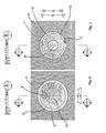
- 1 denotes a supporting wall of a building and 2 one of them with a distance held facade panel.
- An inventive armature for fastening the facade panel 2 has a, suitably made of plastic, holding element 3, from which a threaded rod 4 extends into an introduced into the supporting wall bore 5.
- a first end E1 of the retaining element 3 is located in the vicinity of the threaded rod 4.
- the remote from the threaded rod 4 second end is denoted by E2.
- a channel 7 extends from an annular space 6 formed in the retaining element 3 to the second end E2.
- An opening of the channel 7 provided at the second end E2 is closed by a check valve 8.
- At the first end E1 of the holding element 3 is a flange 9.
- a silicone tube 10 surrounds the holding element 3.
- the silicone tube 10 is fastened with a hose binder 11 on the flange 9.
- the holding element 3 is conically tapered on its outer circumference in the direction of the threaded rod 4. It lies under the intermediary of the silicone tube 10 in a form-fitting manner on a through-hole 2 passing through the facade panel 2.
- An O-ring designated by reference numeral 18 is provided in the vicinity of the second end E2 of the holding member 3 between the holding member 3 and the silicone tube 10.
- the threaded rod 4 engages in a sieve sleeve 13, which is fixed by means of a composite mortar 14 in the bore 5.
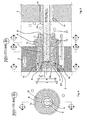
- FIG. 3 shows the conical portion of the support member 3, which rests with the interposition of the silicone tube 10 positively against the wall of the likewise conically shaped through-hole 12.
- Fig. 4 shows a cross-sectional view and a plan view of the second end E2 of the received in the through-hole 12 anchor.
- An undercut structure 15 provided at the second end E2 is made in one-piece construction with the holding element 3.
- Fig. 5 shows the anchor according to Fig. 1 , in which case the channel 7 and the annular space 6 are filled with a viscoplastic thermosetting resin 16. Due to the elasticity of the silicone tube 10 and an injection of the viscoplastic hardening mass, z. B. two-component epoxy resin, forms a curvature in the region of the annular space 6, which secures the retaining element 3 against displacement in the horizontal direction. The O-ring 18 securely prevents unwanted leakage of the two-component epoxy resin between the support member 3 and the silicone tube 10th
- FIG. 12 is a cross-sectional view taken along the line C - C of FIG. From this again the filled with the viscous mass 16 annular space 6 is clearly visible.
- the through hole is widened conically, so that the cone for Tragwand 1 tapers. It is then injected into the bore 5, a composite mortar 14 or a synthetic resin and inserted a screen sleeve or a grid dowel. Subsequently, the armature with the threaded rod 4 is inserted into the sieve sleeve 5 until the retaining element 3 or the silicone tube 10 surrounding the retaining element rests positively on the conical through-bore 12. After curing of the composite mortar 14, a slight tensioning of the retaining element 3 with the facade panel 2 is effected by turning the retaining element 3 clockwise.
- bracing is of course only be produced if the facade panel 2 is still held with the old anchors (not shown here) against the support wall 1 at a distance.
- On the bracing of the support member 3 by turning in a clockwise direction can also be dispensed with, provided that the O-ring 18 is provided.
- the binder may be cement or a plastic.
- the undercut structure 15 serves to intimately bond the holding element 3 with the filling compound 17. Because of the undercut structure 15, the hardened filling compound 17 can not be detached from the holding element 3.
- an axial recess or a blind hole is provided at the second end E2 .
- a blind hole is used to attach a lid for covering the opening formed by the through hole 12.
- a lid which may be made of stainless steel, for example, is preferably used in facade panels 2, which are made of glass.
- the proposed anchor is particularly advantageous because it also thermally induced recesses of the facade panels 2 can be compensated.
- the compensation is achieved by the elastic properties of the retaining element 3 bypassing silicone tube 10. Unwanted constraints of the facade panels 2 can be safely avoided.
Landscapes
- Engineering & Computer Science (AREA)
- Architecture (AREA)
- Civil Engineering (AREA)
- Structural Engineering (AREA)
- Chemical & Material Sciences (AREA)
- Chemical Kinetics & Catalysis (AREA)
- Electrochemistry (AREA)
- Mechanical Engineering (AREA)
- Finishing Walls (AREA)
- Joining Of Building Structures In Genera (AREA)
- Working Measures On Existing Buildindgs (AREA)
Description
- Die Erfindung betrifft eine Vorrichtung und ein Verfahren zur Befestigung von Fassadenplatten (siehe z.B.
EP-A-635 646 - Die Erfindung betrifft insbesondere das Gebiet der Restaurierung von mit Fassadenplatten versehenen Gebäuden. Fassadenplatten sind üblicherweise mit Metallankern an einer Tragwand eines Gebäudes befestigt. Die Metallanker tragen eine Vertikallast der Fassadenplatte in die Tragwand ab. Außerdem halten die Metallanker die mit Abstand zur Tragwand angebrachte Fassadenplatte in horizontaler Richtung.
- Im Laufe der Zeit kann es durch thermisch induzierte Spannungen und aggressive Abgase in der Luft zu einem Ausbrechen der Metallanker kommen. Infolgedessen kann es dazu kommen, dass Fassadenplatten sich lösen und vom Gebäude herabfallen. Das stellt eine erhebliche Gefährdung von Passanten dar. Fassaden mit schadhaften Fassadenankern sind umgehend zu renovieren bzw. zu restaurieren.
- Nach dem Stand der Technik ist es dazu erforderlich, das Gebäude entweder mit neuen Fassadenplatten zu verkleiden oder die alten Fassadenplatten abzunehmen und die Fassade unter Verwendung neuer Anker wieder aufzubauen. Beide Sanierungsmaßnahmen sind äußerst kosten- und zeitaufwändig.
- Daneben ist es auch noch bekannt, zur Sicherung lockerer Fassadenplatten eine Durchgriffsbohrung durch die Fassadenplatte vorzusehen und diese mit einer Schraube an der Tragwand zu sichern. Damit wird zwar ein Herabfallen der Fassadenplatte verhindert, die Fassadenplatte wird jedoch in horizontaler Richtung nicht festgehalten. Insbesondere bei einem Sturm wackeln solche Fassadenplatten. Dadurch bedingt, kann es zu einem Bruch und zum Herabfallen der Fassadenplatte kommen.
- Aufgabe der Erfindung ist es, die Nachteile nach dem Stand der Technik zu beseitigen. Es sollen insbesondere eine Vorrichtung und ein Verfahren angegeben werden, mit denen auf einfache und kostengünstige Weise eine dauerhafte Sanierung von Fassaden möglich ist.
- Diese Aufgabe wird durch die Merkmale der Ansprüche 1 und 12 gelöst. Zweckmäßige Ausgestaltungen ergeben sich aus den Merkmalen der Ansprüche 2 bis 11 und 13 bis 16.
- Mit der vorgeschlagenen Vorrichtung gelingt es auf einfache Weise Fassaden zu sanieren. Zur erneuten Befestigung der Fassadenplatten ist es nicht erforderlich, diese abzunehmen. Sie können an Ort und Stelle erneut befestigt werden. Dabei gewährleistet die vorgeschlagene Vorrichtung sowohl einen vertikalen Lastabtrag als auch eine horizontale Fixierung der Fassadenplatten.
- Nachfolgend wird anhand der Zeichnung ein Ausführungsbeispiel der Erfindung näher erläutert. Es zeigen:
- Fig. 1
- eine erste Querschnittsansicht durch eine Vorrich- tung,
- Fig. 2
- eine Querschnittsansicht gemäß der Schnittlinie C - C in
Fig. 1 , - Fig. 3
- eine Querschnittsansicht gemäß der Schnittlinie B - B in
Fig. 1 , - Fig. 4
- eine Querschnittsansicht gemäß der Schnittlinie A - A in
Fig. 1 , - Fig. 5
- eine zweite Querschnittsansicht der Vorrichtung, wobei ein Ringraum verfüllt ist und
- Fig. 6
- eine Querschnittsansicht gemäß der Schnittlinie C - C in
Fig. 5 . - In den Figuren ist mit 1 eine Tragwand eines Gebäudes und mit 2 eine davon mit einem Abstand gehaltene Fassadenplatte bezeichnet. Ein erfindungsgemäßer Anker zur Befestigung der Fassadenplatte 2 weist ein, zweckmäßigerweise aus Kunststoff hergestelltes, Halteelement 3 auf, von dem sich eine Gewindestange 4 in eine in die Tragwand eingebrachte Bohrung 5 erstreckt. Ein erstes Ende E1 des Halteelements 3 befindet sich in der Nähe der Gewindestange 4. Das entfernt von der Gewindestange 4 befindliche zweite Ende ist mit E2 bezeichnet. Von einem im Halteelement 3 gebildeten Ringraum 6 erstreckt sich zum zweiten Ende E2 ein Kanal 7. Eine am zweiten Ende E2 vorgesehene Öffnung des Kanals 7 ist mit einem Rückschlagventil 8 verschlossen. Am ersten Ende E1 des Halteelements 3 befindet sich ein Flansch 9. Ein Silikonschlauch 10 umgibt das Halteelement 3. Der Silikonschlauch 10 ist mit einem Schlauchbinder 11 am Flansch 9 befestigt. Das Halteelement 3 ist an seinem Außenumfang in Richtung der Gewindestange 4 konisch sich verjüngend ausgebildet. Es liegt unter Vermittlung des Silikonschlauchs 10 formschlüssig an einer die Fassadenplatte 2 durchgreifenden Durchgriffsbohrung 12 an. Ein mit dem Bezugszeichen 18 bezeichneter O-Ring ist in der Nähe des zweiten Endes E2 des Halteelements 3 zwischen dem Halteelement 3 und dem Silikonschlauch 10 vorgesehen.
- Die Gewindestange 4 greift in eine Siebhülse 13 ein, die mittels eines Verbundmörtels 14 in der Bohrung 5 fixiert ist.
- Aus der in
Fig. 2 gezeigten Querschnittsansicht ist nochmals deutlich die Ausbildung des von dem Silikonschlauch 10 umgebenen Ringraums 6 ersichtlich. Die Querschnittsansicht inFig. 3 zeigt den konischen Abschnitt des Halteelements 3, welcher unter Zwischenschaltung des Silikonschlauchs 10 formschlüssig an der Wand der ebenfalls konisch ausgebildeten Durchgriffsbohrung 12 anliegt.Fig. 4 zeigt eine Querschnittsansicht bzw. eine Draufsicht auf das zweite Ende E2 des in der Durchgriffsbohrung 12 aufgenommenen Ankers. Eine am zweiten Ende E2 vorgesehene hinterschnittene Struktur 15 ist in einstückiger Ausbildung mit dem Halteelement 3 hergestellt. -
Fig. 5 zeigt den Anker gemäßFig. 1 , wobei hier der Kanal 7 und der Ringraum 6 mit einem zähelastisch aushärtenden Harz 16 verfüllt sind. Infolge der Elastizität des Silikonschlauchs 10 und einem Einspritzen der zähelastisch aushärtenden Masse, z. B. Zwei-Komponenten-Epoxydharz, bildet sich im Bereich des Ringraums 6 eine Wölbung aus, die das Halteelement 3 gegen Verschieben in horizontaler Richtung sichert. Der O-Ring 18 verhindert sicher ein unerwünschtes Austreten des Zwei-Komponenten-Epoxydharzes zwischen dem Halteelement 3 und dem Silikonschlauch 10. - In
Fig. 6 ist eine Querschnittsansicht gemäß der Schnittlinie C - C gezeigt. Daraus ist nochmals der mit der zähelastischen Masse 16 verfüllte Ringraum 6 klar erkennbar. - Zum Verankern der Fassadenplatte 2 wird zweckmäßigerweise das folgende Arbeitsverfahren durchgeführt:
- Zunächst wird durch die Fassadenplatte 2 mit einem Bohrer eine Durchgangsbohrung und mit demselben Bohrer unmittelbar danach die Bohrung 5 hergestellt. Anschließend wird die Durchgangsbohrung konisch aufgeweitet, so dass sich der Konus zur Tragwand 1 hin verjüngt. Es wird dann in die Bohrung 5 ein Verbundmörtel 14 oder ein Kunstharz eingespritzt und eine Siebhülse bzw. ein Gitterdübel eingesteckt. Anschließend wird der Anker mit der Gewindestange 4 in die Siebhülse 5 eingesteckt, bis das Halteelement 3 bzw. der das Halteelement umgebende Silikonschlauch 10 formschlüssig an der konischen Durchgangsbohrung 12 anliegt. Nach dem Aushärten des Verbundmörtels 14 wird durch Drehen des Halteelements 3 im Uhrzeigersinn eine geringfügige Verspannung des Halteelements 3 mit der Fassadenplatte 2 bewirkt. Eine solche Verspannung ist selbstverständlich nur dann herstellbar, wenn die Fassadenplatte 2 noch mit den alten Ankern (hier nicht gezeigt) gegen die Tragwand 1 auf Abstand gehalten wird. Auf das Verspannen des Halteelements 3 durch Verdrehen im Uhrzeigersinn kann auch verzichtet werden, sofern der O-Ring 18 vorgesehen ist.
- Nach dem Verspannen des Halteelements 3 mit der Fassadenplatte 2 wird eine vorgegebene Menge an Zwei-Komponenten-Epoxydharz durch das Rückschlagventil 8 in den Ringraum 6 gedrückt. Infolgedessen wölbt sich die den Ringraum umgebende aus dem Silikonschlauch 10 gebildete elastische Wand nach außen. Sofern der O-Ring 18 vorgesehen ist, wird auch bei einem geringfügig verkippten Einsetzen des Halteelements 3 in die Durchgangsbohrung 12 stets eine zuverlässige Dichtwirkung erreicht. Ein Austritt des Zwei-Komponenten-Epoxydharzes im Bereich des zweiten Endes E2 wird sicher vermieden. Nach dem Aushärten der zähelastisch aushärtenden Masse 16 sitzt das Halteelement 3 im Wesentlichen unverschiebbar in der Durchgangsbohrung 12. Es ist infolge der elastischen Eigenschaften des Silikonschlauchs 10 elastisch in der Durchgangsbohrung 12 gehalten. Der vorgeschlagene Anker hält die Fassadenplatte 2 in horizontaler Richtung. Gleichzeitig wird auch ein vertikaler Lastabtrag über die Tragwand 1 erreicht.
- Schließlich wird eine verbleibende Öffnung der Durchgangsbohrung 12 z. B. mit einer bindemittelhaltigen Füllmasse 17 ausgefüllt. Bei dem Bindemittel kann es sich Zement oder um einen Kunststoff handeln. Die hinterschnittene Struktur 15 dient einem innigen Verbund des Halteelements 3 mit der Füllmasse 17. Wegen der hinterschnittenen Struktur 15 kann die ausgehärtete Füllmasse 17 sich nicht vom Halteelement 3 lösen.
- Nach einer Ausgestaltung kann es auch sein, dass am zweiten Ende E2 eine axiale Ausnehmung bzw. ein Sackloch, vorgesehen ist. Ein solches Sackloch dient der Befestigung eines Deckels zum Abdecken der durch die Durchgangsbohrung 12 gebildeten Öffnung. Ein solcher Deckel, der beispielsweise aus Edelstahl hergestellt sein kann, wird vorzugsweise bei Fassadenplatten 2 benutzt, die aus Glas hergestellt sind.
- Der vorgeschlagene Anker ist insbesondere deshalb vorteilhaft, weil damit auch thermisch bedingte Ausnehmungen der Fassadenplatten 2 kompensiert werden können. Die Kompensation wird durch die elastischen Eigenschaften des das Halteelement 3 umgehenden Silikonschlauchs 10 erreicht. Unerwünschte Zwängungen der Fassadenplatten 2 können so sicher vermieden werden.
-
- 1
- Tragwand
- 2
- Fassadenplatte
- 3
- Halteelement
- 4
- Gewindestange
- 5
- Bohrung
- 6
- Ringraum
- 7
- Kanal
- 8
- Rückschlagventil
- 9
- Flansch
- 10
- Silikonschlauch
- 11
- Schlauchbinder
- 12
- Durchgangsbohrung
- 13
- Siebhülse
- 14
- Verbundmörtel
- 15
- hinterschnittene Struktur
- 16
- zähelastisch aushärtende Masse
- 17
- Füllmasse
- 18
- O-Ring
- E1
- erstes Ende
- E2
- zweites Ende
Claims (16)
- Vorrichtung zur Befestigung von Fassadenplatten (2) mit einer sich von einem Halteelement (3) erstreckenden Gewindestange (4),
wobei das Halteelement (3) an seinem nahe bei der Gewindestange (4) befindlichen ersten Ende (E1) einen Ringraum (6) mit einer aus einem elastischen Material (10) hergestellten Wand aufweist,
wobei ein Kanal (7) vom Ringraum (6) sich zu einem entfernt von der Gewindestange (4) befindlichen zweiten Ende (E2) erstreckt,
und wobei am zweiten Ende (E2) ein Ventil (8) vorgesehen ist, mit dem der Kanal (7) verschließbar ist. - Vorrichtung nach Anspruch 1, wobei das Halteelement (3) am zweiten Ende (E2) einen größeren Durchmesser als am ersten Ende (E1) aufweist.
- Vorrichtung nach einem der vorhergehenden Ansprüche, wobei das Halteelement (3) sich vom zweiten Ende (E2) zum ersten Ende (E1) hin konisch verjüngt.
- Vorrichtung nach einem der vorhergehenden Ansprüche, wobei das Halteelement (3) einstückig aus Kunststoff hergestellt ist.
- Vorrichtung nach einem der vorhergehenden Ansprüche, wobei der Ringraum (6) eine am ersten Ende (E1) gebildete radial umlaufende Ausnehmung aufweist.
- Vorrichtung nach einem der vorhergehenden Ansprüche, wobei auf dem Halteelement (3) ein elastischer Schlauch (10) aufgenommen ist.
- Vorrichtung nach einem der vorhergehenden Ansprüche, wobei der, vorzugsweise aus Silikon hergestellte, elastische Schlauch (10) die Wand des Ringraums (6) bildet.
- Vorrichtung nach einem der vorhergehenden Ansprüche, wobei der elastische Schlauch (10) sich im Wesentlichen über die gesamte axiale Länge des Halteelements (3) erstreckt.
- Vorrichtung nach einem der vorhergehenden Ansprüche, wobei der elastische Schlauch (10) an einem am ersten Ende (E1) des Halteelements (3) befindlichen Flansch (9) mittels eines Spannelements (11), vorzugsweise einem Schlauchbinder, befestigt ist.
- Vorrichtung nach einem der vorhergehenden Ansprüche, wobei am zweiten Ende (E2) ein hinterschnitten ausgebildeter Vorsprung (15) vorgesehen ist.
- Vorrichtung nach einem der vorhergehenden Ansprüche, wobei am zweiten Ende (E2) eine zentrische Ausnehmung vorgesehen ist.
- Verfahren zur Befestigung von Fassadenplatten (2) unter Verwendung der Vorrichtung nach einem der vorhergehenden Ansprüche, mit folgenden Schritten:a) Herstellen einer die Fassadenplatte (2) durchgreifenden und in eine Tragwand reichenden Bohrung (12, 5),b) Aufweiten des Radius der die Fassadenplatte (2) durchgreifenden Durchgriffsbohrung (12) in der Nähe einer Sichtseite der Fassadenplatte (2),c) Einbringen eines Dübels (13) in die in die Tragwand (1) eingebrachte Bohrung (5) unter Verwendung einer aushärtenden Masse (14),d) Einstecken der Gewindestange (4) in den Dübel (13), so dass das Halteelement (3) am Innenumfang der Durchgriffsbohrung (12) anliegt,e) Einschrauben der Vorrichtung und Verspannen mit der Fassadenplatte (2),f) Einspritzen einer zähelastisch aushärtenden Masse (16) durch das Ventil (8), so dass die den Ringraum (6) umgebende Wand (10) sich aufweitet und damit das Halteelement (3) in der Durchgriffsbohrung (12) gehalten wird.
- Verfahren nach Anspruch 12, wobei der Radius der Durchgriffsbohrung (12) konisch aufgeweitet wird.
- Verfahren nach einem der Ansprüche 12 oder 13, wobei als zähelastisch aushärtende Masse (16) ein Epoxydharz verwendet wird.
- Verfahren nach einem der Ansprüche 12 bis 14, wobei eine an der Sichtseite der Fassadenplatte (2) verbleibenden Öffnung der Durchgriffsbohrung (12) nach dem Aushärten der zähelastisch aushärtenden Masse (16) verschlossen wird.
- Verfahren nach einem der Ansprüche 12 bis 15, wobei die Öffnung mit einem Deckel oder einer bindemittelhaltigen Masse (17) verschlossen wird.
Applications Claiming Priority (5)
| Application Number | Priority Date | Filing Date | Title |
|---|---|---|---|
| DE10256637 | 2002-12-03 | ||
| DE10256637 | 2002-12-03 | ||
| DE10300854A DE10300854B8 (de) | 2002-12-03 | 2003-01-10 | Vorrichtung und Verfahren zur Befestigung von Fassadenplatten |
| DE10300854 | 2003-01-10 | ||
| PCT/EP2003/013654 WO2004051027A1 (de) | 2002-12-03 | 2003-12-03 | Vorrichtung und verfahren zur befestigung von fassadenplatten |
Publications (2)
| Publication Number | Publication Date |
|---|---|
| EP1567733A1 EP1567733A1 (de) | 2005-08-31 |
| EP1567733B1 true EP1567733B1 (de) | 2010-02-10 |
Family
ID=32471498
Family Applications (1)
| Application Number | Title | Priority Date | Filing Date |
|---|---|---|---|
| EP03812172A Expired - Lifetime EP1567733B1 (de) | 2002-12-03 | 2003-12-03 | Vorrichtung und verfahren zur befestigung von fassadenplatten |
Country Status (5)
| Country | Link |
|---|---|
| US (1) | US7594366B2 (de) |
| EP (1) | EP1567733B1 (de) |
| AU (1) | AU2003296606A1 (de) |
| CA (1) | CA2508371C (de) |
| WO (1) | WO2004051027A1 (de) |
Families Citing this family (6)
| Publication number | Priority date | Publication date | Assignee | Title |
|---|---|---|---|---|
| BE1018314A5 (fr) * | 2009-04-06 | 2010-08-03 | Girten Gerard | Systeme de fixation pour un materiau isolant, de facon a garder un vide d'air de part et d'autre de celui-ci. |
| WO2012112133A1 (en) * | 2011-02-17 | 2012-08-23 | Logan William F | Panel assembly for mounting to the facade of a building |
| US8567141B2 (en) | 2011-02-17 | 2013-10-29 | William F. Logan | Panel assembly for mounting to the façade of a building |
| WO2012174257A2 (en) * | 2011-06-14 | 2012-12-20 | Wathne John M | System of tying, cleaning and re-cementing masonry using port anchors |
| EP4010538B1 (de) * | 2019-08-05 | 2026-03-18 | Hickory Design Pty Ltd | Vorgegossene bauplatte |
| WO2024025925A1 (en) * | 2022-07-26 | 2024-02-01 | Certainteed Gypsum, Inc. | Building surface product including embedded fastener, building surface system, and method of manufacture |
Family Cites Families (19)
| Publication number | Priority date | Publication date | Assignee | Title |
|---|---|---|---|---|
| US4096672A (en) * | 1974-11-14 | 1978-06-27 | Artur Fisher | Anchoring arrangement for securing an object to a support structure having an internal cavity |
| DE2830073A1 (de) * | 1978-07-08 | 1980-01-17 | Fischer Artur Dr H C | Verankerung eines befestigungselementes |
| EP0014728B1 (de) | 1979-02-26 | 1982-12-22 | Günter Joly | Hohler Verpressdübel |
| DE3004276A1 (de) | 1980-02-06 | 1981-08-13 | Upat Gmbh & Co, 7830 Emmendingen | Verfahren zum befestigen eines verblendmauerwerkes und huelse zur durchfuehrung des verfahrens |
| DE3007434A1 (de) | 1980-02-28 | 1981-09-03 | Günter 4930 Detmold Joly | Verpressduebel |
| US4928451A (en) * | 1986-05-30 | 1990-05-29 | Tech Research, Inc. | Anchor apparatus for a tendon in prestressed concrete slab |
| AU612641B2 (en) | 1987-05-07 | 1991-07-18 | Gene Alfonse Falco | Masonry anchor |
| US4930284A (en) * | 1987-12-21 | 1990-06-05 | Falco Gene A | Masonry anchor |
| DE3800833C2 (de) * | 1988-01-14 | 1996-09-19 | Fischer Artur Werke Gmbh | Verbunddübel |
| US4883396A (en) * | 1988-01-22 | 1989-11-28 | U.S.E. Diamond, Inc. | Dual expansion and non-expansion anchor |
| DE3900671C1 (en) | 1989-01-12 | 1990-03-08 | Messerschmitt-Boelkow-Blohm Gmbh, 8012 Ottobrunn, De | Process for securing the position of a metal insert in a plastic wall |
| DE3912526A1 (de) * | 1989-04-17 | 1990-10-18 | Hilti Ag | Verankerung an plattenfoermigen bauteilen |
| DE8906126U1 (de) * | 1989-05-18 | 1990-04-19 | Bergwerksverband Gmbh, 4300 Essen | Injektionsrohr mit Ankerwirkung |
| GB2263958B (en) | 1992-02-05 | 1995-06-07 | Exchem Plc | Anchoring of fixing elements in bores |
| DE9310816U1 (de) | 1993-07-20 | 1994-11-24 | Fischerwerke Artur Fischer Gmbh & Co Kg, 72178 Waldachtal | Verblendanker |
| US5636486A (en) * | 1994-01-04 | 1997-06-10 | Hall; John S. | Brick tie |
| EP0863353A3 (de) | 1997-03-03 | 2000-02-23 | Anton H. Erb | Verankerungsvorrichtung |
| DE19961555A1 (de) | 1999-12-20 | 2001-06-21 | Saint Gobain Isover G & H Ag | Befestigungssystem mit Montagehülse zur beabstandeten Anordnung von Gegenständen |
| US7404274B2 (en) * | 2003-11-12 | 2008-07-29 | Hayes John T | Masonry wall anchoring system |
-
2003
- 2003-12-03 EP EP03812172A patent/EP1567733B1/de not_active Expired - Lifetime
- 2003-12-03 CA CA2508371A patent/CA2508371C/en not_active Expired - Fee Related
- 2003-12-03 US US10/537,305 patent/US7594366B2/en not_active Expired - Fee Related
- 2003-12-03 WO PCT/EP2003/013654 patent/WO2004051027A1/de not_active Ceased
- 2003-12-03 AU AU2003296606A patent/AU2003296606A1/en not_active Abandoned
Also Published As
| Publication number | Publication date |
|---|---|
| CA2508371C (en) | 2012-01-31 |
| EP1567733A1 (de) | 2005-08-31 |
| US7594366B2 (en) | 2009-09-29 |
| AU2003296606A1 (en) | 2004-06-23 |
| US20060162273A1 (en) | 2006-07-27 |
| CA2508371A1 (en) | 2004-06-17 |
| WO2004051027A1 (de) | 2004-06-17 |
Similar Documents
| Publication | Publication Date | Title |
|---|---|---|
| DE102004051739B4 (de) | Verschlussdeckel für eine Befestigungsanordnung | |
| EP2978911B1 (de) | Bauanordnung und verfahren zum festlegen eines gerüsts an einer gebäudewand | |
| DE1802770A1 (de) | Verfahren zum Verankern eines Befestigungselementes in einer Wand od.dgl. und zugehoeriges Befestigungselement | |
| DE2624559A1 (de) | Gebirgsanker | |
| CH620496A5 (en) | Method of anchoring a tube, arrangement for carrying out the method, and slack anchor produced according to the method | |
| EP0203416B1 (de) | Verankerung einer Gewindestange mittels einer Verbundmasse | |
| EP1567733B1 (de) | Vorrichtung und verfahren zur befestigung von fassadenplatten | |
| EP2550431B1 (de) | Verfahren zur nachträglichen ertüchtigung eines befestigungsmittels und hierfür geeignete injektage-unterlegscheibe | |
| DE4121620A1 (de) | Ankerstange zur verankerung mittels kunstharz | |
| CH666310A5 (en) | Facade cladding fixing device - comprises bracket extending through insulation material and accommodating anchoring member for cladding | |
| DE10300854B3 (de) | Vorrichtung und Verfahren zur Befestigung von Fassadenplatten | |
| DE3322198C2 (de) | ||
| DE10060510A1 (de) | Verbundanker | |
| DE102012017704A1 (de) | Anordnung zur hochfesten Verankerung eines einen Spannstab aufweisenden Spannglieds in einem Bauteil sowie Verfahren zur Herstellung einer solchen Verankerung | |
| DE102010037755A1 (de) | Befestigungsanordnung | |
| AT525254B1 (de) | Verankerung eines Bauwerkteils an einem ortsfesten Untergrund | |
| EP2902645A1 (de) | Schraube zum Einschrauben in ein Bohrloch und Vorspann-Anordnung mit einer derartigen in das Bohrloch eingeschraubten Schraube | |
| DE9400659U1 (de) | Bauelement mit einer Betonplatte und wenigstens einer daran befestigten Steinplatte | |
| DE9414703U1 (de) | Injektionsdübel | |
| EP3981950A1 (de) | Verankerungssystem für ein bauelement an einem bauwerk | |
| EP4268693B1 (de) | Verfahren zur montage einer trennwand an einer wand | |
| DE8421167U1 (de) | Vorrichtung zum Abdichten von Rissen und dergl. in Bauteilen | |
| DE4128459C1 (en) | Method for repairing building wall cladding - involves installing fixing ,prior to pouring of material, for removal after hardening | |
| DE20218372U1 (de) | Zentrierhilfe zur Injektionsbefestigung | |
| DE10161426A1 (de) | Verankerung für verspannte Konstruktionen |
Legal Events
| Date | Code | Title | Description |
|---|---|---|---|
| PUAI | Public reference made under article 153(3) epc to a published international application that has entered the european phase |
Free format text: ORIGINAL CODE: 0009012 |
|
| 17P | Request for examination filed |
Effective date: 20050601 |
|
| AK | Designated contracting states |
Kind code of ref document: A1 Designated state(s): AT BE BG CH CY CZ DE DK EE ES FI FR GB GR HU IE IT LI LU MC NL PT RO SE SI SK TR |
|
| AX | Request for extension of the european patent |
Extension state: AL LT LV MK |
|
| DAX | Request for extension of the european patent (deleted) | ||
| GRAP | Despatch of communication of intention to grant a patent |
Free format text: ORIGINAL CODE: EPIDOSNIGR1 |
|
| GRAJ | Information related to disapproval of communication of intention to grant by the applicant or resumption of examination proceedings by the epo deleted |
Free format text: ORIGINAL CODE: EPIDOSDIGR1 |
|
| GRAP | Despatch of communication of intention to grant a patent |
Free format text: ORIGINAL CODE: EPIDOSNIGR1 |
|
| RAP1 | Party data changed (applicant data changed or rights of an application transferred) |
Owner name: VIEZENS, LUDWIG Owner name: WEISE + STRATTNER GMBH |
|
| RTI1 | Title (correction) |
Free format text: DEVICE AND METHOD FOR FASTENING FACADE PLATES |
|
| GRAS | Grant fee paid |
Free format text: ORIGINAL CODE: EPIDOSNIGR3 |
|
| GRAA | (expected) grant |
Free format text: ORIGINAL CODE: 0009210 |
|
| AK | Designated contracting states |
Kind code of ref document: B1 Designated state(s): AT BE BG CH CY CZ DE DK EE ES FI FR GB GR HU IE IT LI LU MC NL PT RO SE SI SK TR |
|
| REG | Reference to a national code |
Ref country code: GB Ref legal event code: FG4D Free format text: NOT ENGLISH |
|
| REG | Reference to a national code |
Ref country code: CH Ref legal event code: EP |
|
| REG | Reference to a national code |
Ref country code: IE Ref legal event code: FG4D |
|
| REF | Corresponds to: |
Ref document number: 50312413 Country of ref document: DE Date of ref document: 20100325 Kind code of ref document: P |
|
| REG | Reference to a national code |
Ref country code: CH Ref legal event code: NV Representative=s name: GLN S.A. |
|
| REG | Reference to a national code |
Ref country code: ES Ref legal event code: FG2A Ref document number: 2340996 Country of ref document: ES Kind code of ref document: T3 |
|
| REG | Reference to a national code |
Ref country code: NL Ref legal event code: VDEP Effective date: 20100210 |
|
| PG25 | Lapsed in a contracting state [announced via postgrant information from national office to epo] |
Ref country code: PT Free format text: LAPSE BECAUSE OF FAILURE TO SUBMIT A TRANSLATION OF THE DESCRIPTION OR TO PAY THE FEE WITHIN THE PRESCRIBED TIME-LIMIT Effective date: 20100611 |
|
| PG25 | Lapsed in a contracting state [announced via postgrant information from national office to epo] |
Ref country code: FI Free format text: LAPSE BECAUSE OF FAILURE TO SUBMIT A TRANSLATION OF THE DESCRIPTION OR TO PAY THE FEE WITHIN THE PRESCRIBED TIME-LIMIT Effective date: 20100210 Ref country code: SI Free format text: LAPSE BECAUSE OF FAILURE TO SUBMIT A TRANSLATION OF THE DESCRIPTION OR TO PAY THE FEE WITHIN THE PRESCRIBED TIME-LIMIT Effective date: 20100210 |
|
| PG25 | Lapsed in a contracting state [announced via postgrant information from national office to epo] |
Ref country code: EE Free format text: LAPSE BECAUSE OF FAILURE TO SUBMIT A TRANSLATION OF THE DESCRIPTION OR TO PAY THE FEE WITHIN THE PRESCRIBED TIME-LIMIT Effective date: 20100210 Ref country code: CY Free format text: LAPSE BECAUSE OF FAILURE TO SUBMIT A TRANSLATION OF THE DESCRIPTION OR TO PAY THE FEE WITHIN THE PRESCRIBED TIME-LIMIT Effective date: 20100210 Ref country code: SE Free format text: LAPSE BECAUSE OF FAILURE TO SUBMIT A TRANSLATION OF THE DESCRIPTION OR TO PAY THE FEE WITHIN THE PRESCRIBED TIME-LIMIT Effective date: 20100210 Ref country code: NL Free format text: LAPSE BECAUSE OF FAILURE TO SUBMIT A TRANSLATION OF THE DESCRIPTION OR TO PAY THE FEE WITHIN THE PRESCRIBED TIME-LIMIT Effective date: 20100210 Ref country code: RO Free format text: LAPSE BECAUSE OF FAILURE TO SUBMIT A TRANSLATION OF THE DESCRIPTION OR TO PAY THE FEE WITHIN THE PRESCRIBED TIME-LIMIT Effective date: 20100210 Ref country code: GR Free format text: LAPSE BECAUSE OF FAILURE TO SUBMIT A TRANSLATION OF THE DESCRIPTION OR TO PAY THE FEE WITHIN THE PRESCRIBED TIME-LIMIT Effective date: 20100511 |
|
| PG25 | Lapsed in a contracting state [announced via postgrant information from national office to epo] |
Ref country code: CZ Free format text: LAPSE BECAUSE OF FAILURE TO SUBMIT A TRANSLATION OF THE DESCRIPTION OR TO PAY THE FEE WITHIN THE PRESCRIBED TIME-LIMIT Effective date: 20100210 Ref country code: SK Free format text: LAPSE BECAUSE OF FAILURE TO SUBMIT A TRANSLATION OF THE DESCRIPTION OR TO PAY THE FEE WITHIN THE PRESCRIBED TIME-LIMIT Effective date: 20100210 Ref country code: BG Free format text: LAPSE BECAUSE OF FAILURE TO SUBMIT A TRANSLATION OF THE DESCRIPTION OR TO PAY THE FEE WITHIN THE PRESCRIBED TIME-LIMIT Effective date: 20100510 |
|
| PLBE | No opposition filed within time limit |
Free format text: ORIGINAL CODE: 0009261 |
|
| STAA | Information on the status of an ep patent application or granted ep patent |
Free format text: STATUS: NO OPPOSITION FILED WITHIN TIME LIMIT |
|
| 26N | No opposition filed |
Effective date: 20101111 |
|
| PG25 | Lapsed in a contracting state [announced via postgrant information from national office to epo] |
Ref country code: DK Free format text: LAPSE BECAUSE OF FAILURE TO SUBMIT A TRANSLATION OF THE DESCRIPTION OR TO PAY THE FEE WITHIN THE PRESCRIBED TIME-LIMIT Effective date: 20100210 |
|
| BERE | Be: lapsed |
Owner name: WEISE + STRATTNER G.M.B.H. Effective date: 20101231 Owner name: VIEZENS, LUDWIG Effective date: 20101231 |
|
| PG25 | Lapsed in a contracting state [announced via postgrant information from national office to epo] |
Ref country code: MC Free format text: LAPSE BECAUSE OF NON-PAYMENT OF DUE FEES Effective date: 20101231 |
|
| PG25 | Lapsed in a contracting state [announced via postgrant information from national office to epo] |
Ref country code: BE Free format text: LAPSE BECAUSE OF NON-PAYMENT OF DUE FEES Effective date: 20101231 |
|
| PG25 | Lapsed in a contracting state [announced via postgrant information from national office to epo] |
Ref country code: LU Free format text: LAPSE BECAUSE OF NON-PAYMENT OF DUE FEES Effective date: 20101203 Ref country code: HU Free format text: LAPSE BECAUSE OF FAILURE TO SUBMIT A TRANSLATION OF THE DESCRIPTION OR TO PAY THE FEE WITHIN THE PRESCRIBED TIME-LIMIT Effective date: 20100811 |
|
| PG25 | Lapsed in a contracting state [announced via postgrant information from national office to epo] |
Ref country code: TR Free format text: LAPSE BECAUSE OF FAILURE TO SUBMIT A TRANSLATION OF THE DESCRIPTION OR TO PAY THE FEE WITHIN THE PRESCRIBED TIME-LIMIT Effective date: 20100210 |
|
| REG | Reference to a national code |
Ref country code: CH Ref legal event code: PCAR Free format text: NEW ADDRESS: AVENUE EDOUARD-DUBOIS 20, 2000 NEUCHATEL (CH) |
|
| REG | Reference to a national code |
Ref country code: FR Ref legal event code: PLFP Year of fee payment: 13 |
|
| REG | Reference to a national code |
Ref country code: CH Ref legal event code: PFA Owner name: WEISE + STRATTNER GMBH, DE Free format text: FORMER OWNER: WEISE + STRATTNER GMBH, DE |
|
| REG | Reference to a national code |
Ref country code: FR Ref legal event code: PLFP Year of fee payment: 14 |
|
| REG | Reference to a national code |
Ref country code: FR Ref legal event code: PLFP Year of fee payment: 15 |
|
| REG | Reference to a national code |
Ref country code: CH Ref legal event code: NV Representative=s name: BOVARD SA NEUCHATEL CONSEILS EN PROPRIETE INTE, CH |
|
| PGFP | Annual fee paid to national office [announced via postgrant information from national office to epo] |
Ref country code: IE Payment date: 20191217 Year of fee payment: 17 |
|
| PGFP | Annual fee paid to national office [announced via postgrant information from national office to epo] |
Ref country code: IT Payment date: 20191216 Year of fee payment: 17 Ref country code: FR Payment date: 20191219 Year of fee payment: 17 |
|
| PGFP | Annual fee paid to national office [announced via postgrant information from national office to epo] |
Ref country code: AT Payment date: 20191213 Year of fee payment: 17 Ref country code: CH Payment date: 20191220 Year of fee payment: 17 |
|
| PGFP | Annual fee paid to national office [announced via postgrant information from national office to epo] |
Ref country code: GB Payment date: 20191220 Year of fee payment: 17 Ref country code: ES Payment date: 20200122 Year of fee payment: 17 |
|
| REG | Reference to a national code |
Ref country code: CH Ref legal event code: PL |
|
| REG | Reference to a national code |
Ref country code: AT Ref legal event code: MM01 Ref document number: 457391 Country of ref document: AT Kind code of ref document: T Effective date: 20201203 |
|
| GBPC | Gb: european patent ceased through non-payment of renewal fee |
Effective date: 20201203 |
|
| PG25 | Lapsed in a contracting state [announced via postgrant information from national office to epo] |
Ref country code: AT Free format text: LAPSE BECAUSE OF NON-PAYMENT OF DUE FEES Effective date: 20201203 Ref country code: IE Free format text: LAPSE BECAUSE OF NON-PAYMENT OF DUE FEES Effective date: 20201203 Ref country code: IT Free format text: LAPSE BECAUSE OF NON-PAYMENT OF DUE FEES Effective date: 20201203 Ref country code: FR Free format text: LAPSE BECAUSE OF NON-PAYMENT OF DUE FEES Effective date: 20201231 |
|
| PG25 | Lapsed in a contracting state [announced via postgrant information from national office to epo] |
Ref country code: CH Free format text: LAPSE BECAUSE OF NON-PAYMENT OF DUE FEES Effective date: 20201231 Ref country code: GB Free format text: LAPSE BECAUSE OF NON-PAYMENT OF DUE FEES Effective date: 20201203 Ref country code: LI Free format text: LAPSE BECAUSE OF NON-PAYMENT OF DUE FEES Effective date: 20201231 |
|
| REG | Reference to a national code |
Ref country code: ES Ref legal event code: FD2A Effective date: 20220207 |
|
| PG25 | Lapsed in a contracting state [announced via postgrant information from national office to epo] |
Ref country code: ES Free format text: LAPSE BECAUSE OF NON-PAYMENT OF DUE FEES Effective date: 20201204 |
|
| PGFP | Annual fee paid to national office [announced via postgrant information from national office to epo] |
Ref country code: DE Payment date: 20221121 Year of fee payment: 20 |
|
| REG | Reference to a national code |
Ref country code: DE Ref legal event code: R071 Ref document number: 50312413 Country of ref document: DE |