EP1566892B1 - Kommunikationsendgerät - Google Patents
Kommunikationsendgerät Download PDFInfo
- Publication number
- EP1566892B1 EP1566892B1 EP20050250885 EP05250885A EP1566892B1 EP 1566892 B1 EP1566892 B1 EP 1566892B1 EP 20050250885 EP20050250885 EP 20050250885 EP 05250885 A EP05250885 A EP 05250885A EP 1566892 B1 EP1566892 B1 EP 1566892B1
- Authority
- EP
- European Patent Office
- Prior art keywords
- value
- transmission power
- threshold value
- predicted
- detection
- Prior art date
- Legal status (The legal status is an assumption and is not a legal conclusion. Google has not performed a legal analysis and makes no representation as to the accuracy of the status listed.)
- Expired - Lifetime
Links
- 238000004891 communication Methods 0.000 title claims description 28
- 230000005540 biological transmission Effects 0.000 claims description 108
- 238000001514 detection method Methods 0.000 claims description 68
- 230000008054 signal transmission Effects 0.000 claims description 11
- 230000001413 cellular effect Effects 0.000 description 30
- 230000005856 abnormality Effects 0.000 description 14
- 238000000034 method Methods 0.000 description 11
- 230000008569 process Effects 0.000 description 11
- 238000005516 engineering process Methods 0.000 description 6
- 230000002159 abnormal effect Effects 0.000 description 4
- 230000006870 function Effects 0.000 description 4
- 230000006378 damage Effects 0.000 description 3
- 238000004519 manufacturing process Methods 0.000 description 3
- 230000003321 amplification Effects 0.000 description 2
- 238000004590 computer program Methods 0.000 description 2
- 230000006872 improvement Effects 0.000 description 2
- 238000003199 nucleic acid amplification method Methods 0.000 description 2
- 238000012545 processing Methods 0.000 description 2
- 230000009467 reduction Effects 0.000 description 2
- 230000003044 adaptive effect Effects 0.000 description 1
- 230000015556 catabolic process Effects 0.000 description 1
- 230000001419 dependent effect Effects 0.000 description 1
- 238000013461 design Methods 0.000 description 1
- 238000010586 diagram Methods 0.000 description 1
- 230000002349 favourable effect Effects 0.000 description 1
- 238000012986 modification Methods 0.000 description 1
- 230000004048 modification Effects 0.000 description 1
- 230000001012 protector Effects 0.000 description 1
Images
Classifications
-
- H—ELECTRICITY
- H04—ELECTRIC COMMUNICATION TECHNIQUE
- H04B—TRANSMISSION
- H04B1/00—Details of transmission systems, not covered by a single one of groups H04B3/00 - H04B13/00; Details of transmission systems not characterised by the medium used for transmission
- H04B1/02—Transmitters
- H04B1/04—Circuits
- H04B1/0466—Fault detection or indication
-
- G—PHYSICS
- G07—CHECKING-DEVICES
- G07F—COIN-FREED OR LIKE APPARATUS
- G07F19/00—Complete banking systems; Coded card-freed arrangements adapted for dispensing or receiving monies or the like and posting such transactions to existing accounts, e.g. automatic teller machines
- G07F19/20—Automatic teller machines [ATMs]
- G07F19/201—Accessories of ATMs
-
- H—ELECTRICITY
- H03—ELECTRONIC CIRCUITRY
- H03F—AMPLIFIERS
- H03F1/00—Details of amplifiers with only discharge tubes, only semiconductor devices or only unspecified devices as amplifying elements
- H03F1/02—Modifications of amplifiers to raise the efficiency, e.g. gliding Class A stages, use of an auxiliary oscillation
- H03F1/0205—Modifications of amplifiers to raise the efficiency, e.g. gliding Class A stages, use of an auxiliary oscillation in transistor amplifiers
-
- H—ELECTRICITY
- H03—ELECTRONIC CIRCUITRY
- H03F—AMPLIFIERS
- H03F1/00—Details of amplifiers with only discharge tubes, only semiconductor devices or only unspecified devices as amplifying elements
- H03F1/52—Circuit arrangements for protecting such amplifiers
-
- H—ELECTRICITY
- H03—ELECTRONIC CIRCUITRY
- H03F—AMPLIFIERS
- H03F3/00—Amplifiers with only discharge tubes or only semiconductor devices as amplifying elements
- H03F3/20—Power amplifiers, e.g. Class B amplifiers, Class C amplifiers
- H03F3/21—Power amplifiers, e.g. Class B amplifiers, Class C amplifiers with semiconductor devices only
-
- G—PHYSICS
- G07—CHECKING-DEVICES
- G07D—HANDLING OF COINS OR VALUABLE PAPERS, e.g. TESTING, SORTING BY DENOMINATIONS, COUNTING, DISPENSING, CHANGING OR DEPOSITING
- G07D2211/00—Paper-money handling devices
-
- H—ELECTRICITY
- H03—ELECTRONIC CIRCUITRY
- H03F—AMPLIFIERS
- H03F2200/00—Indexing scheme relating to amplifiers
- H03F2200/105—A non-specified detector of the power of a signal being used in an amplifying circuit
Definitions
- the present invention has been made in view of the above circumstances, and embodiments of the invention can provide a communication terminal that is capable of detecting an abnormal APC control operation for transmission power control to prevent circuitry from becoming faulty or damaged and providing productivity improvement and production cost reduction, for instance, by eliminating (or at least reducing) the need for a pre-shipment process for threshold value adjustment.
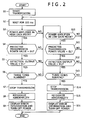
- step S4 If the CPU 7 judges in step S4 that the predicted transmission power value is greater than the high gain predicted upper limit threshold value EU, the program flow proceeds to step S5. If, on the other hand, the CPU 7 judges that the predicted transmission power value is not greater than the high gain predicted upper limit threshold value EU, the program flow proceeds to step S10.
- step S13 the CPU 7 checks whether query steps S11 and S12 were answered "Yes” due to an unexpected abnormality. More specifically, step S13 is performed to judge whether query steps S11 and S12 are all answered "Yes” three times running. If the CPU 7 judges in step S13 that the query steps were all answered "Yes” three times running, the program flow proceeds to step S14. If, on the other hand, the CPU 7 judges that the query steps were not all answered "Yes" three times running, the program flow returns to step S2.
- the present invention is not only applicable to cellular phone terminals but also applicable to various apparatuses having a transmission section for providing transmission power control, such as PDAs (Personal Digital Assistants) and personal computers having a communication function.
- PDAs Personal Digital Assistants
- personal computers having a communication function.
Landscapes
- Engineering & Computer Science (AREA)
- Power Engineering (AREA)
- Computer Networks & Wireless Communication (AREA)
- Signal Processing (AREA)
- Business, Economics & Management (AREA)
- Accounting & Taxation (AREA)
- Finance (AREA)
- Physics & Mathematics (AREA)
- General Physics & Mathematics (AREA)
- Transmitters (AREA)
- Mobile Radio Communication Systems (AREA)
Claims (5)
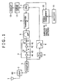
- Kommunikationsendgerät zum Ausführen einer Übertragungsleistungssteuerung, um die Stärke einer Funkwelle, die von einer Basisstation empfangen wird, auf einem bestimmten Pegel zu halten, wenn eine drahtlose Kommunikation mit der Basisstation aufgebaut werden soll, wobei das Kommunikationsendgerät enthält:einen Abschnitt (7) zum Erzeugen eines vorhergesagten Übertragungsleistungswerts, um einen vorhergesagten Übertragungsleistungswert zu erzeugen, der dem durch die Übertragungsleistungssteuerung zu übertragenden Leistungswert entspricht;einen Detektionswert-Erzeugungsabschnitt (8) zum Erzeugen eines Detektionswerts für das von einer Antenne auszugebende Übertragungssignal;einen Verstärkungsmodus-Auswahlabschnitt (4, 41, 43) zum Auswählen eines Modus mit hoher Verstärkung oder eines Modus mit niedriger Verstärkung; undeinen Steuerabschnitt (7) zum Vergleichen des vorhergesagten Übertragungsleistungswerts und des Detektionswerts und zum Anhalten des Signalübertragungsbetriebs, falls die Differenz zwischen dem vorhergesagten Übertragungsleistungswert und dem Detektionswert nicht kleiner als ein vorgegebener Wert ist,wobei dann, wenn der Modus mit hoher Verstärkung gewählt ist, der Steuerabschnitt dazu ausgelegt ist, im Betrieb den vorhergesagten Übertragungsleistungswert mit einem ersten Schwellenwert (EU) zu vergleichen und den Detektionswert mit einem zweiten Schwellenwert (DL), der kleiner als der erste Schwellenwert ist, zu vergleichen; undwobei dann, wenn der Modus mit niedriger Verstärkung gewählt ist, der Steuerabschnitt dazu ausgelegt ist, im Betrieb den vorhergesagten Übertragungsleistungswert mit einem dritten Schwellenwert (EL) zu vergleichen und den Detektionswert mit einem vierten Schwellenwert (DU), der größer als der dritte Schwellenwert ist, zu vergleichen.
- Kommunikationsendgerät nach Anspruch 1, wobei dann, wenn im Modus mit hoher Verstärkung der vorhergesagte Übertragungsleistungswert größer ist als der erste Schwellenwert und der Detektionswert kleiner ist als der zweite Schwellenwert, der Steuerabschnitt dazu ausgelegt ist, im Betrieb darauf zu schließen, dass die Differenz zwischen dem vorhergesagten Übertragungsleistungswert und dem Detektionswert nicht kleiner ist als ein vorgegebener Wert.
- Kommunikationsendgerät nach Anspruch 1, wobei dann, wenn im Modus mit niedriger Verstärkung der vorhergesagte Übertragungsleistungswert kleiner ist als der dritte Schwellenwert und der Detektionswert größer ist als der vierte Schwellenwert, der Steuerabschnitt dazu ausgelegt ist, im Betrieb darauf zu schließen, dass die Differenz zwischen dem vorhergesagten Übertragungsleistungswert und dem Detektionswert nicht kleiner ist als ein vorgegebener Wert.
- Kommunikationsendgerät nach Anspruch 1, das ferner enthält:einen Leistungsversorgungsabschnitt (10, 11) zum Liefern von Leistung zu verschiedenen Abschnitten,wobei der Steuerabschnitt, nachdem der Signalübertragungsbetrieb angehalten worden ist, den Leistungsversorgungsabschnitt steuert, um die Lieferung von Leistung zu den verschiedenen Abschnitten anzuhalten.
- Kommunikationsendgerät nach Anspruch 1, wobei der Steuerabschnitt den Signalübertragungsbetrieb anhält, wenn ein Zustand, in dem die Differenz zwischen dem vorhergesagten Übertragungsleistungswert und dem Detektionswert nicht kleiner ist als ein vorgegebener Wert, in einer vorgegebenen Anzahl aufeinander folgender Zeiten in festen Zeitintervallen angetroffen wird.
Applications Claiming Priority (2)
| Application Number | Priority Date | Filing Date | Title |
|---|---|---|---|
| JP2004041967A JP3900433B2 (ja) | 2004-02-18 | 2004-02-18 | 通信端末 |
| JP2004041967 | 2004-02-18 |
Publications (2)
| Publication Number | Publication Date |
|---|---|
| EP1566892A1 EP1566892A1 (de) | 2005-08-24 |
| EP1566892B1 true EP1566892B1 (de) | 2011-10-05 |
Family
ID=34709102
Family Applications (1)
| Application Number | Title | Priority Date | Filing Date |
|---|---|---|---|
| EP20050250885 Expired - Lifetime EP1566892B1 (de) | 2004-02-18 | 2005-02-16 | Kommunikationsendgerät |
Country Status (5)
| Country | Link |
|---|---|
| US (1) | US7454226B2 (de) |
| EP (1) | EP1566892B1 (de) |
| JP (1) | JP3900433B2 (de) |
| KR (1) | KR20060042039A (de) |
| CN (1) | CN1758545B (de) |
Families Citing this family (6)
| Publication number | Priority date | Publication date | Assignee | Title |
|---|---|---|---|---|
| JP4684842B2 (ja) * | 2005-10-14 | 2011-05-18 | 京セラ株式会社 | 送信出力制御装置 |
| CN100423469C (zh) * | 2006-02-28 | 2008-10-01 | 北京天碁科技有限公司 | 一种基于移动终端功率预测的下行功率控制系统与方法 |
| WO2008007428A1 (fr) * | 2006-07-12 | 2008-01-17 | Fujitsu Limited | Appareil de transmission radio et procédé de commande de la puissance de transmission |
| CN101534547B (zh) * | 2009-04-15 | 2011-12-07 | 北京天碁科技有限公司 | 一种移动终端及下行功率控制方法 |
| CN103369652B (zh) * | 2012-03-30 | 2016-03-16 | 展讯通信(上海)有限公司 | 下行功率控制方法、装置与移动终端 |
| CN110336622A (zh) * | 2019-06-27 | 2019-10-15 | 维沃移动通信有限公司 | 发射链路保护方法和移动终端 |
Family Cites Families (13)
| Publication number | Priority date | Publication date | Assignee | Title |
|---|---|---|---|---|
| US5287555A (en) * | 1991-07-22 | 1994-02-15 | Motorola, Inc. | Power control circuitry for a TDMA radio frequency transmitter |
| JP2826003B2 (ja) * | 1991-11-29 | 1998-11-18 | 松下電器産業株式会社 | 送信出力制御回路 |
| US5196808A (en) * | 1991-12-02 | 1993-03-23 | Motorola, Inc. | RF amplifier protector and method |
| FI101505B (fi) * | 1995-05-10 | 1998-06-30 | Nokia Mobile Phones Ltd | Menetelmä suuntakytkimellä toteutetun tehonmittauksen parantamiseksi p ienillä tehotasoilla |
| WO1997039545A1 (en) * | 1996-04-12 | 1997-10-23 | Ntt Mobile Communications Network Inc. | Method and instrument for measuring receiving sir and transmission power controller |
| JPH10173548A (ja) | 1996-12-09 | 1998-06-26 | Toshiba Corp | 送信出力制御方法および装置 |
| JPH1188226A (ja) | 1997-09-12 | 1999-03-30 | Saitama Nippon Denki Kk | デジタル携帯電話機の送信制御回路 |
| JPH11112366A (ja) * | 1997-10-07 | 1999-04-23 | Fujitsu Ltd | 自動送信電力制御回路 |
| US6430402B1 (en) * | 1998-09-14 | 2002-08-06 | Conexant Systems, Inc. | Power amplifier saturation prevention method, apparatus, and communication system incorporating the same |
| JP2000341145A (ja) * | 1999-05-27 | 2000-12-08 | Alps Electric Co Ltd | 送信回路及びその送信回路を備えた送受信装置 |
| JP3739985B2 (ja) * | 2000-01-31 | 2006-01-25 | 富士通株式会社 | 送信機利得安定化装置 |
| US20030114182A1 (en) * | 2001-12-19 | 2003-06-19 | Chan Paul L. | Adaptive power amplifier |
| JP3958066B2 (ja) * | 2002-02-21 | 2007-08-15 | ソニー・エリクソン・モバイルコミュニケーションズ株式会社 | 送信出力回路および移動体通信端末 |
-
2004
- 2004-02-18 JP JP2004041967A patent/JP3900433B2/ja not_active Expired - Fee Related
-
2005
- 2005-02-16 EP EP20050250885 patent/EP1566892B1/de not_active Expired - Lifetime
- 2005-02-17 US US11/059,907 patent/US7454226B2/en not_active Expired - Fee Related
- 2005-02-17 KR KR20050013080A patent/KR20060042039A/ko not_active Abandoned
- 2005-02-18 CN CN200510067646.2A patent/CN1758545B/zh not_active Expired - Fee Related
Also Published As
| Publication number | Publication date |
|---|---|
| JP2005236572A (ja) | 2005-09-02 |
| US7454226B2 (en) | 2008-11-18 |
| US20050192043A1 (en) | 2005-09-01 |
| KR20060042039A (ko) | 2006-05-12 |
| EP1566892A1 (de) | 2005-08-24 |
| CN1758545B (zh) | 2014-02-19 |
| JP3900433B2 (ja) | 2007-04-04 |
| CN1758545A (zh) | 2006-04-12 |
Similar Documents
| Publication | Publication Date | Title |
|---|---|---|
| EP2637301B1 (de) | Schaltkreis, kommunikationsvorrichtung und verfahren zum schützen eines leistungsverstärkers | |
| US6615028B1 (en) | System and method for selecting amplifiers in a communications device | |
| US6980780B2 (en) | Power controller | |
| US12519428B2 (en) | Radio frequency power amplifier, radio frequency front-end module, and communication terminal | |
| US20050026641A1 (en) | Mobile communicatiion system, mobile communication terminal, power control method used therefor, and program therefor | |
| US8565669B2 (en) | Methods and apparatus for power reduction in a transceiver | |
| US9043617B2 (en) | Device incorporating data communication function | |
| US9480017B2 (en) | Dynamic power management control | |
| EP1566892B1 (de) | Kommunikationsendgerät | |
| US6025753A (en) | Method and apparatus for amplifying a signal | |
| US20080171523A1 (en) | Power Amplifier Bias Control | |
| EP0388895B1 (de) | Sender mit variabler Sendeleistung | |
| JP2008147934A (ja) | Tdd方式の無線送受信装置 | |
| US6002928A (en) | Switching apparatus and method for transceiver of cellular base station in code division multiple access mobile telecommunication system | |
| US6552608B2 (en) | Linear amplifier | |
| EP0617523A2 (de) | Digitales Funkübertragungsgerät mit Übertragungsfehlerkontrolle | |
| CN114844472B (zh) | 一种电源控制方法、系统和电子设备 | |
| US9008600B2 (en) | Wireless communication receiver having one signal processing circuit whose operation mode is adjusted by monitoring signal level of specific signal of preceding signal processing circuit and related wireless communication method | |
| US7450918B2 (en) | Apparatus and method for controlling gain of a transceiving device in a wireless terminal for a communication system | |
| US7102445B2 (en) | Power amplifier module | |
| EP3665783B1 (de) | Rauscharmer verstärkerschutz | |
| US20250392267A1 (en) | High-frequency switching device | |
| KR20250179992A (ko) | Rf 전력 증폭기 보호장치 | |
| KR20000007319A (ko) | 기지국의 파워 디바이스 제어방법 | |
| KR100629245B1 (ko) | 이동통신시스템의 잡음전력 차단장치 |
Legal Events
| Date | Code | Title | Description |
|---|---|---|---|
| PUAI | Public reference made under article 153(3) epc to a published international application that has entered the european phase |
Free format text: ORIGINAL CODE: 0009012 |
|
| AK | Designated contracting states |
Kind code of ref document: A1 Designated state(s): AT BE BG CH CY CZ DE DK EE ES FI FR GB GR HU IE IS IT LI LT LU MC NL PL PT RO SE SI SK TR |
|
| AX | Request for extension of the european patent |
Extension state: AL BA HR LV MK YU |
|
| 17P | Request for examination filed |
Effective date: 20060206 |
|
| AKX | Designation fees paid |
Designated state(s): DE FR GB |
|
| 17Q | First examination report despatched |
Effective date: 20091204 |
|
| GRAP | Despatch of communication of intention to grant a patent |
Free format text: ORIGINAL CODE: EPIDOSNIGR1 |
|
| GRAS | Grant fee paid |
Free format text: ORIGINAL CODE: EPIDOSNIGR3 |
|
| GRAA | (expected) grant |
Free format text: ORIGINAL CODE: 0009210 |
|
| AK | Designated contracting states |
Kind code of ref document: B1 Designated state(s): DE FR GB |
|
| REG | Reference to a national code |
Ref country code: GB Ref legal event code: FG4D |
|
| REG | Reference to a national code |
Ref country code: DE Ref legal event code: R096 Ref document number: 602005030340 Country of ref document: DE Effective date: 20111201 |
|
| PLBE | No opposition filed within time limit |
Free format text: ORIGINAL CODE: 0009261 |
|
| STAA | Information on the status of an ep patent application or granted ep patent |
Free format text: STATUS: NO OPPOSITION FILED WITHIN TIME LIMIT |
|
| 26N | No opposition filed |
Effective date: 20120706 |
|
| REG | Reference to a national code |
Ref country code: DE Ref legal event code: R097 Ref document number: 602005030340 Country of ref document: DE Effective date: 20120706 |
|
| REG | Reference to a national code |
Ref country code: FR Ref legal event code: PLFP Year of fee payment: 12 |
|
| PGFP | Annual fee paid to national office [announced via postgrant information from national office to epo] |
Ref country code: DE Payment date: 20160218 Year of fee payment: 12 |
|
| PGFP | Annual fee paid to national office [announced via postgrant information from national office to epo] |
Ref country code: GB Payment date: 20160217 Year of fee payment: 12 Ref country code: FR Payment date: 20160218 Year of fee payment: 12 |
|
| REG | Reference to a national code |
Ref country code: DE Ref legal event code: R119 Ref document number: 602005030340 Country of ref document: DE |
|
| GBPC | Gb: european patent ceased through non-payment of renewal fee |
Effective date: 20170216 |
|
| REG | Reference to a national code |
Ref country code: FR Ref legal event code: ST Effective date: 20171031 |
|
| PG25 | Lapsed in a contracting state [announced via postgrant information from national office to epo] |
Ref country code: DE Free format text: LAPSE BECAUSE OF NON-PAYMENT OF DUE FEES Effective date: 20170901 Ref country code: FR Free format text: LAPSE BECAUSE OF NON-PAYMENT OF DUE FEES Effective date: 20170228 |
|
| PG25 | Lapsed in a contracting state [announced via postgrant information from national office to epo] |
Ref country code: GB Free format text: LAPSE BECAUSE OF NON-PAYMENT OF DUE FEES Effective date: 20170216 |