EP1566778B1 - Spielgerät - Google Patents
Spielgerät Download PDFInfo
- Publication number
- EP1566778B1 EP1566778B1 EP05003921A EP05003921A EP1566778B1 EP 1566778 B1 EP1566778 B1 EP 1566778B1 EP 05003921 A EP05003921 A EP 05003921A EP 05003921 A EP05003921 A EP 05003921A EP 1566778 B1 EP1566778 B1 EP 1566778B1
- Authority
- EP
- European Patent Office
- Prior art keywords
- game
- image
- player
- gaming machine
- screen
- Prior art date
- Legal status (The legal status is an assumption and is not a legal conclusion. Google has not performed a legal analysis and makes no representation as to the accuracy of the status listed.)
- Expired - Lifetime
Links
- 230000006870 function Effects 0.000 description 9
- 230000004048 modification Effects 0.000 description 8
- 238000012986 modification Methods 0.000 description 8
- 238000000034 method Methods 0.000 description 7
- 238000001514 detection method Methods 0.000 description 6
- 230000010365 information processing Effects 0.000 description 6
- 230000003287 optical effect Effects 0.000 description 6
- 230000004044 response Effects 0.000 description 6
- 230000002093 peripheral effect Effects 0.000 description 4
- 240000007509 Phytolacca dioica Species 0.000 description 3
- 238000010586 diagram Methods 0.000 description 3
- 239000004973 liquid crystal related substance Substances 0.000 description 3
- 230000000981 bystander Effects 0.000 description 2
- 239000003086 colorant Substances 0.000 description 2
- 230000001276 controlling effect Effects 0.000 description 2
- 238000003708 edge detection Methods 0.000 description 2
- 239000011521 glass Substances 0.000 description 2
- 238000005286 illumination Methods 0.000 description 2
- 230000001737 promoting effect Effects 0.000 description 2
- 230000001419 dependent effect Effects 0.000 description 1
- 230000000694 effects Effects 0.000 description 1
- PCHJSUWPFVWCPO-UHFFFAOYSA-N gold Chemical compound [Au] PCHJSUWPFVWCPO-UHFFFAOYSA-N 0.000 description 1
- 229910052737 gold Inorganic materials 0.000 description 1
- 239000010931 gold Substances 0.000 description 1
- 239000007788 liquid Substances 0.000 description 1
- 230000001012 protector Effects 0.000 description 1
- 230000001105 regulatory effect Effects 0.000 description 1
- 229910052709 silver Inorganic materials 0.000 description 1
- 239000004332 silver Substances 0.000 description 1
Images


Classifications
-
- A—HUMAN NECESSITIES
- A63—SPORTS; GAMES; AMUSEMENTS
- A63F—CARD, BOARD, OR ROULETTE GAMES; INDOOR GAMES USING SMALL MOVING PLAYING BODIES; VIDEO GAMES; GAMES NOT OTHERWISE PROVIDED FOR
- A63F13/00—Video games, i.e. games using an electronically generated display having two or more dimensions
-
- A—HUMAN NECESSITIES
- A63—SPORTS; GAMES; AMUSEMENTS
- A63F—CARD, BOARD, OR ROULETTE GAMES; INDOOR GAMES USING SMALL MOVING PLAYING BODIES; VIDEO GAMES; GAMES NOT OTHERWISE PROVIDED FOR
- A63F13/00—Video games, i.e. games using an electronically generated display having two or more dimensions
- A63F13/20—Input arrangements for video game devices
- A63F13/21—Input arrangements for video game devices characterised by their sensors, purposes or types
- A63F13/213—Input arrangements for video game devices characterised by their sensors, purposes or types comprising photodetecting means, e.g. cameras, photodiodes or infrared cells
-
- G—PHYSICS
- G07—CHECKING-DEVICES
- G07F—COIN-FREED OR LIKE APPARATUS
- G07F17/00—Coin-freed apparatus for hiring articles; Coin-freed facilities or services
- G07F17/32—Coin-freed apparatus for hiring articles; Coin-freed facilities or services for games, toys, sports, or amusements
-
- G—PHYSICS
- G07—CHECKING-DEVICES
- G07F—COIN-FREED OR LIKE APPARATUS
- G07F17/00—Coin-freed apparatus for hiring articles; Coin-freed facilities or services
- G07F17/32—Coin-freed apparatus for hiring articles; Coin-freed facilities or services for games, toys, sports, or amusements
- G07F17/3202—Hardware aspects of a gaming system, e.g. components, construction, architecture thereof
- G07F17/3204—Player-machine interfaces
- G07F17/3211—Display means
-
- A—HUMAN NECESSITIES
- A63—SPORTS; GAMES; AMUSEMENTS
- A63F—CARD, BOARD, OR ROULETTE GAMES; INDOOR GAMES USING SMALL MOVING PLAYING BODIES; VIDEO GAMES; GAMES NOT OTHERWISE PROVIDED FOR
- A63F2300/00—Features of games using an electronically generated display having two or more dimensions, e.g. on a television screen, showing representations related to the game
- A63F2300/10—Features of games using an electronically generated display having two or more dimensions, e.g. on a television screen, showing representations related to the game characterized by input arrangements for converting player-generated signals into game device control signals
- A63F2300/1068—Features of games using an electronically generated display having two or more dimensions, e.g. on a television screen, showing representations related to the game characterized by input arrangements for converting player-generated signals into game device control signals being specially adapted to detect the point of contact of the player on a surface, e.g. floor mat, touch pad
- A63F2300/1075—Features of games using an electronically generated display having two or more dimensions, e.g. on a television screen, showing representations related to the game characterized by input arrangements for converting player-generated signals into game device control signals being specially adapted to detect the point of contact of the player on a surface, e.g. floor mat, touch pad using a touch screen
-
- A—HUMAN NECESSITIES
- A63—SPORTS; GAMES; AMUSEMENTS
- A63F—CARD, BOARD, OR ROULETTE GAMES; INDOOR GAMES USING SMALL MOVING PLAYING BODIES; VIDEO GAMES; GAMES NOT OTHERWISE PROVIDED FOR
- A63F2300/00—Features of games using an electronically generated display having two or more dimensions, e.g. on a television screen, showing representations related to the game
- A63F2300/10—Features of games using an electronically generated display having two or more dimensions, e.g. on a television screen, showing representations related to the game characterized by input arrangements for converting player-generated signals into game device control signals
- A63F2300/1087—Features of games using an electronically generated display having two or more dimensions, e.g. on a television screen, showing representations related to the game characterized by input arrangements for converting player-generated signals into game device control signals comprising photodetecting means, e.g. a camera
Definitions
- the present invention mainly relates to a gaming machine, and more particularly to a gaming machine which specifies a position of a player's hand, performs a control of a game based on this position, and specifies the player by detecting the position from which the hand extends.
- Such a gaming machine is provided with manipulating parts the number of which corresponds to the number of players and the players perform the game by manipulating the corresponding manipulating parts.
- the present invention proposes a gaming machine which allows a plurality of players to perform a game using the same game table simultaneously.
- the players perform the game at positions arranged around a game table (for example, a betting table of roulette, a baccarat table of baccarat) provided to the gaming machine.
- the positions where the player plays the game are fixed by arranging chairs or the like to predetermined positions around the game table.
- a gaming machine characterized by including a game table display means (an image display unit) which displays an image corresponding to a game table, a position detecting means (a position detecting part) which detects positions of indicators on the game table display means, a player specifying means (a player specifying part) which specifies players corresponding to the indicators based on the positional relationship between the positions of the indicators detected by the position detecting means and the game table display means, and a control means (a game control part) which performs a control of the game based on information on the positions detected by the position detecting means and information on the players specified based on the player specifying means.
- a gaming machine which allows the plurality of players to advance the game by simultaneously indicating the betting positions or the like on the table screen which constitutes one game table, it is possible to specify which players perform the betting and which positions the players bet, and an amount (the number of bets) which the players bet.
- the number of bets is determined using the change of the positions of the indicators (for example, when the number that the player taps the table screen is treated as the number of bets, the vertical movement of the indicator is detected), it is possible to obtain the number of bets more accurately based on the inputting from the player terminal units and can be reflected on the advancement of the game.
- the result of the game is clearly recognized not only by the players but also by bystanders around the gaming machine thus promoting the desire of the bystanders to take part in the game.
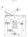
- Fig. 1 is a view showing a basic constitutional example of an image display system according to the first embodiment of the present invention.
- a player specifying unit 70 which specifies a player corresponding to the shade PS based on the image data from the image taking unit 40, and an main control device 60 which instructs an image to be projected to the screen unit 10 to the image control unit 30 based on the positional information from the position detecting unit 50 and the information of the player specifying unit 70 which specifies the player.
- the screen unit 10, the projecting unit 20 and the image control unit 30 cooperatively function as an image display unit 80 which displays an image such as a game table to the player.
- the screen unit 10 has a light transmitting property and allows light from a front surface and a back surface thereof to pass therethrough.
- the screen unit 10 is, for example, a transmissive screen for a liquid crystal projector.
- the projecting unit 20 is an optical projecting system which is capable of projecting an optical image to the screen unit 10 based on the image data and is a liquid crystal projector (DLP (Digital Liquid Protector)), for example.
- the light source LS is preferably a light source which emits a white light.
- the image taking unit 40 is a unit which generates the image data of the back surface of the screen unit 10 and is, for example, a digital camera, a digital video camera, a CCD camera unit, or the like.
- the image control unit 30, the position detecting unit 50, the main control device 60 and the player specifying unit 70 are respectively constituted of a device which includes a central processingunit (CPU), amainmemory (RAM), a read only memory (ROM), an input/output device (I/O), and an external storage device such as a hard disc device or the like when necessary. That is, these units may be formed of an information processing unit such as a computer, a workstation, an LSI chip or the like. In the above-mentioned ROM or the hard disc device, a program which allows the information processing device to function as the image control unit 30, the position detecting unit 50 or the main control device 60 is stored.
- the image control unit 30, the position detecting unit 50 or the main control device 60 can be realized. Further, the above-mentioned program is not always necessary to be stored in the storage device in the inside of the information processing device and may be provided from an external device (for example, an ASP (a server of an application service provider or the like)) and may be stored in the main memory.
- an external device for example, an ASP (a server of an application service provider or the like)
- the image control unit 30, the position detecting unit 50, the main control device 60, and the player specifying unit 70 may be respectively realized by individual information processing device or one information processing device may be configured to function as the image control unit 40, the position detecting unit 50, the main control device 60 and the player specifying unit 70.
- the image control unit 30 stores a plurality of image data to be displayed to the user, wherein the necessary image data is read out in response to a command from the main control device 60 and is subjected to the image processing when necessary, and is provided to the projecting unit 20.
- the position detecting unit 50 receives the image data of the back surface of the screen unit 10 from the image taking unit 40, detects the position of the shade PS of the indicator P by performing the necessary image processing on the image data, and outputs the detected position as the positional information.
- image processing threshold value processing for performing the region extracting of the shade PS, the edge detection for extracting a profile of the shade PS or the like is considered.
- the position detecting unit 50 generates the positional information of the shade PS by making use of the coordinate positional information of pixels of a shade region or a profile line obtained by these threshold value processing or the edge detection.
- the main control device 60 has a function of controlling the operation of the whole image display system 1, wherein the main control device 60 instructs the image data to be outputted and the timing at which the image data is outputted or the like the image control unit 30 and, at the same time, instructs the image control unit 30 to change the image data in response to the positional information of the shade PS from the position detecting unit 50.
- the player specifying unit 70 checks whether the shades PS fall within regions for specifying the players, wherein the regions are predetermined on the table screen for respective players (also referred to as "player specifying regions"). Thereafter, the player specifying unit 70 specifies the players corresponding to the shades PS as a result, and outputs the information indicating the players.
- the player specifying region is a region in which the indicator never fails to pass when the player indicates on the input region on the table screen allocated to himself/herself with the indicating poriton P, that is, the region which is determined based on the sitting position given to the player, the shape and the size of the gaming machine, the expected player's physical structure of the player and the like.
- the gaming machine which allows the plurality of players to advance the game while indicating the betting positions or the like on the table screen which constitutes one game table simultaneously, it is possible to specify which positions the players bet.
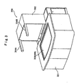
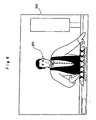
- Fig. 3 is a perspective view of an appearance of a gamingmachine which uses the image display system 1 according to the present invention.
- the gaming machine is explained as a device which allows users to play a baccarat game, the gaming machine according to this embodiment is not limited to the baccarat game. That is, the gaming machine according to this embodiment is applicable to any game such as poker, black jack, bridge or roulette or the like so long as the image display system 1 according to the present invention is applicable.
- the gaming machine 300 includes a table part 301 and a front display 302 which is mounted on a rear portion of the table part 301.
- Table part 301 houses the optical system and information processing equipment which constitute the image display system 1 therein.
- An opening is formed in a center portion of an upper surface of the table part 301 and a transmissive screen 303 which constitutes the screen unit 10 is extended over the opening.
- the transmissive screen 303 functions as an upper display (hereinafter referred to as "table screen 306") which constitutes the image display unit 80 which displays the game image to the users.
- a transparent plate member such as a glass panel thus preventing the transmissive screen 303 from being broken or smeared even when the player touches the table screen 306 with his/her hand which constitutes the indicator P.
- Fluorescent lumps 304A, 304B which constitute the light sources LS are formed both ends of an upper portion of the front display 302 and hence, the shade PS of the indicator P is projected on the transmissive screen 303.
- the arrangement position of the fluorescent lumps 304A, 304B is not always limited to the mode shown in Fig. 3 . That is, the fluorescent lumps 304A, 304B may be arranged at any position so long as the shade PS of the indicator P is projected on the transmissive screen 303. Further, when there is illumination which allows the shade PS of the indicator P to be projected on the transmissive screen 303 at locations where the gaming machine 300 is installed, the fluorescent lumps 304A, 304B may not be provided.
- the transmissive screen 303 is fixed in a state that the transmissive screen 303 is protected by a glass plate or the like.
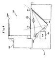
- a mirror 401 is arranged in an inclined state below the transmissive screen 303.
- a digital liquid crystal projector (hereinafter referred to as "DLP") 402 which corresponds to the projecting unit 20
- DVC digital video camera
- the mirror 401 reflects the image radiated from the DLP 402 toward the transmissive screen 303 and the distance between the mirror 401 and the DLP 402 and an angle of a reflection surface are adjusted so as to project the image with a desired size.
- the mirror 401 is arranged in a state that the mirror reflects the image of the back surface of the transmissive screen 303 toward the digital video camera 403 and the distance between the mirror 401 and the digital video camera 403 and an angle of a reflection surface with respect to the transmissive screen 303/the digital video camera 403 is adjusted such that the digital video camera 403 can photographs the back surface of the transmissive screen 303.
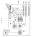
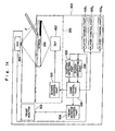
- FIG. 5 is a block diagram showing the electrical constitutional example of the gaming machine 300.
- the gaming machine 300 is provided with the transmissive screen 303.
- the DLP 402 which constitutes the projecting unit 20 optically projects the image related to the game to the transmissive screen 303.
- a screen control part 501 which constitutes the image control unit 30 supplies the image data (hereinafter referred to as "front surface image data") to the DLP 402.
- the digital video camera 403 which constitutes the image taking unit 40 photographs the back surface of the transmissive screen 303 and outputs image data (also referred to as "back surface image data") obtained by photographing the back surface of the transmissive screen 303.
- a position detecting part 503 which constitutes the position detecting unit 50 detects the position indicated by the indicator P by processing this back surface image data and outputs the positional information.
- the front display control part 504 outputs image data of the image to be displayed on the front display 302 (hereinafter referred to as "front image data") in response to the instruction from the game control part 502.
- the front display 302 receives and displays the front image data.
- the image displayed on the front display 302 informs, in cooperation with the image displayed on the transmissive screen 303, that is, the table screen 306, the situation, the progress and the like of the game to the users.
- FIG. 7 is a screen example displayed on the table screen 306 (transmissive screen 303) of the gaming machine 300.
- a screen which imitates a baccarat table is displayed on the table screen 306.
- regions 701, 702, 703 for betting to "BANKER”, “PLAYER”, "DRAW” are displayed for five respective players.
- the number of chips, an amount of money and the number of credits for betting can be decided by the player using a betting button of a player terminal part 505 described later.
- a pile of chips 706 which each player possesses can be also displayed on the table screen 306.
- the image is changed to allow the table screen 306 to perform the display in which the number of chips which are bet are moved to any one of the regions 701, 702, 703 which are designated by the indicator P from a pile of chips in front of the player.
- the table screen 306 includes regions 704, 705 to which the dealer 601 distributes cards of BANKDER and PLAYER and images of cards are displayed on these regions 704, 705.
- Each player terminal part 505 is a terminal which receives coins, bills, prepaid cards, credit cards or the like and changes them to credits (medals /coins) which can be used in the gaming machine 300.
- the player terminal part 405 also has a delivery function of paying out the credits which the player terminal part 405 possesses in response to the payout indication from the player at a point of time that the payout indication is made and a bet inputting function for determining the number of bets, an amount of money and the number of credits in the game. The player performs the game using this player terminal part 505 and the indicator P.
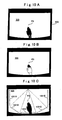
- Fig. 8A shows a state in which the shade PS of the indicator P is not projected to the transmissive screen 303 and shows an example of an image which the video camera 403 photographs the back surface of the transmissive screen 303 by way of the mirror 401.
- the video camera 403 is adjusted to photograph not only the transmissive screen 303 but also a peripheral portion 800 which surrounds the transmissive screen 303.
- the peripheral portion 800 is, for example, a fixed frame which is provided for fixing the transmissive screen 303 to a top plate of the table part and is preferably colored in black or in a dark color close to black.
- the exposure of the video camera 403 is adjusted such that the image displayed on the front surface of the transmissive screen 303 is changed to white in color and disappears.
- the video camera 403 has the automatic exposure adjusting function, since the exposure is adjusted in conformity with the peripheral portion 800 which is colored in black or in the dark color close to black and hence, it is possible to automatically exclude the image displayed on the front surface of the transmissive screen 303 without performing the exposure adjustment particularly.
- Fig. 8B shows a state in which the shade PS of the indicator P is projected to the transmissive screen 303, and also shows an example of an image which the video camera 403 photographs the back surface of the transmissive screen 303 by way of the mirror 401.
- the shade PS of the hand which constitutes the indicator P is present on the transmissive screen 303.
- the shade PS is constituted of an umbra PS1 which is a thick shade and a penumbra PS2 which is a thin shade.
- the umbra PS1 and the penumbra PS2 are formed due to the difference in distance between the transmissive screen 303 and the hand.
- Fig. 9 is a flow chart showing an example of position detecting processing which performs the position detection of the indicator P and the player specifying processing using the back surface image data.
- step S901 the screen back surface photographing processing is performed (step S901). That is, the video camera 403 photographs the back surface of the transmissive screen 303 by way of the mirror 401 and outputs the image as shown in Fig. 8B as the back surface image data to the position detecting part 503.
- Fig. 8C is an image view which displays the back surface image data after the binarization processing.
- the thin portion such as the penumbra PS2 is eliminated and the distal end portion of the indicator P is left and hence, it becomes clear which position the indicator P is indicating.
- a proper threshold value is set to enable the specifying of the distal end portion of the indicator P. Since the proper value of the threshold value is changed depending on the environment around the gaming machine 300 (brightness of the peripheral illumination or the like), an operation test may be performed after installing the gaming machine 300 so as to find out the proper threshold value.
- the position detecting part 503 performs the position detecting processing based on the back surface image data after the binarization processing (step S903).
- the position detecting part 503 obtains the coordinates value (x, y values) of pixels which have black values based on the back surface image data after binarization processing and generates the positional information based on the obtained coordinate values.
- the positional information may be the coordinate value of the pixel which constitutes a peak of the distal end portion. Alternatively, an average value or a center value of the coordinate values of all pixels which possess black values may be selected.
- the threshold value is set to leave only the black region as the shade while discarding the penumbra portion and other portions.
- the player specifying part 506 sets the threshold value and performs the binarization processing such that the not only the distal end portion but also the penumbra portion and other portions remains as the shade to enable the recognition of the whole indicator P.
- Fig. 10C shows an image of the back surface image data of the screen 303 after performing the binarization processing by the player specifying part 506.
- the player specifying part 506 stores the respective coordinates data of player specifying regions 1001A to 10001E.
- the player specifying part 506 determines which one of the player specifying regions 1001A to 100E the shape PS is included based on the coordinates of the pixels which constitute the shade PS and outputs a player identifier corresponding to the player specifying region including the shade PS.
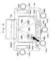
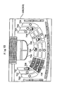
- Fig. 11A is a plan view of the gaming machine 300 as viewed from above and is a view showing the player specifying regions 1001A to 1000E which are formed on a table screen 306, and Fig. 11B is a front view of the gaming machine 300 which corresponds to Fig. 11A .
- the gaming machine 300 is provided with stools 1101A to 1101E which allow five players at maximum can sit and the region that each player's hand can reach is limited.
- player terminal parts 505A to 505E which are incorporated in the table part 301 are provided.
- Each one of the player terminal portions 505A to 505E is provided with a betting button, a canceling button, a payout button (not shown in the drawing) and receives an inputting instruction from the player.
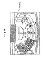
- Fig. 12 is a view showing a state in which the player indicates the position in the region 1102B and is a plan view of the gaming machine 300 as viewed from above.
- the player designates the position in the inside of the region 1102B on the table screen 306 with his/her hand 1201 which constitutes the indicator P.
- the player specifying part 506 determines the shade of the hand 1201 as the hand of the player (sitting on the stool 1101B and using the player terminal part 505B) corresponding to the player specifying region 1101B.
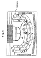
- Fig. 13 shows a state in which the player indicates the position in the region 1102C.
- the player designates the position in the inside of the region 1102C on the table screen 306 with his/her hand 1301 which constitutes the indicator P.
- the player specifying part 506 determines the shade of the hand 1301 as the hand of the player (sitting on the stool 1101C and using the player terminal part 505C) corresponding to the player specifying region 1001C.
- the gaming machine 300 which can use the transmissive screen 303 which constitutes the screen unit 10 as the image display unit as well as the image input unit and, at the same time, can specify the players based on the inputting from the transmissive screen 303.
- Fig. 14 shows the modification of the gaming machine 300.
- the video camera 403 does not photograph the shade PS of the indicator P from above the table screen 305, but photographs the image containing the real image, and the position detecting part 503 determines the position indicated by the indicator P based on the real image.
- the gaming machine 300 of this modification is substantially equal to the gaming machine shown in Fig. 5 with respect to other constitutional elements and manner of operation.
- the piles of chips 706 displayed on the table screen 305 are displayed in a mode (for example, color, pattern, shape or the like of the chips) which differs from a mode of the piles of chips 706 of other player.
- the present invention also includes the constitution which displays an object to be displayed other than the piles of chips in modes different from each other corresponding to the results of the game of respective players.
- Fig. 15 is a view showing a display example of the table screen 305 in the second embodiment.
- a mode in which in a state that the second player from the left facing the gaming machine wins the game, one of the regions 701, 702, 703 which corresponds to the second player is displayed in a flickering manner with color (for example, yellow) different from color (for example, green) which is usually displayed.
- the results of the game may be the results of the respective individual games or a total of a plurality of continuous individual games (for example, plus/minus of chip credit which the player has in hand after finishing of 10 games counted from the starting of the game.
- the above-mentioned "results of game” do not simply classify the display mode based on only the winning or the losing. That is, on the premise that the player wins the game, the display mode is made different whether the winning acquires the specified number of chips or not.
- Fig. 16 shows a display example of the table screen 305 in which the player who wins the game with the number of chips which exceeds the specified number and the player who wins the game with the number of chips which does not exceed the specified number are determined.
- one of the regions 701, 702, 703 which corresponds to the first player from the left is displayed in a flickering manner with color (for example, silver) different from color (for example, green) which is usually displayed and, at the same time, one of the regions 701, 702, 703 which corresponds to the second player from the left is displayed in a flickering manner with color (for example, gold) different from color (for example, green) which is usually displayed and also different from the color displayed in one of the regions 701, 702, 703 which corresponds to the first player.
- color for example, silver
- color for example, green
- the display modes may be made different from each other only by regions which are relevant to winning out of the regions 701, 702, 703, for example.
- the result of the game turns out to be "TIE”
- the display mode may be made different only with respect to the region 701 which corresponds to "TIE”.
- the present invention is not limited to the gaming machine and is applicable to all devices and systems which perform the reception of inputting of the users by making use of the image display and the displayed image such as the image display system for presentation, the demonstration device for promoting sales and the like.
Landscapes
- Engineering & Computer Science (AREA)
- Multimedia (AREA)
- Physics & Mathematics (AREA)
- General Physics & Mathematics (AREA)
- Human Computer Interaction (AREA)
- Display Devices Of Pinball Game Machines (AREA)
- Slot Machines And Peripheral Devices (AREA)
- Pinball Game Machines (AREA)
- Nitrogen And Oxygen Or Sulfur-Condensed Heterocyclic Ring Systems (AREA)
Claims (3)
- Spielautomat, der so eingerichtet ist, dass er es einer Vielzahl von Spielern gestattet, ein Spiel unter Verwendung eines gemeinsamen Spieltischs gleichzeitig durchzuführen, wobei der Spielautomat (300) umfasst:eine Spieltisch-Anzeigeeinrichtung (10, 303), die über eine Bildschirmfunktion verfügt, die so eingerichtet ist, dass sie ein Bild zu einem Spiel anzeigt, das eine Projektionseinheit (20) projiziert, und die Lichtdurchlässigkeit aufweist;gekennzeichnet durch
eine Bildaufnahmeeinrichtung (40), die so eingerichtet ist, dass sie ein Bild einer Rückseite der Spieltisch-Anzeigeeinrichtung (10, 303) aufnimmt, an der ein Schatten (PS) einer Zeigeeinrichtung (P) ausgebildet ist, und Bilddaten der Rückseite erzeugt;
eine Positionserfassungseinrichtung (50, 503), die so eingerichtet ist, dass sie die Bilddaten empfängt, eine Position des Schattens (PS) der Zeigeeinrichtung (P) in der Spieltisch-Anzeigeeinrichtung (10, 303) auf Basis der Bilddaten erfasst und Positionsinformationen der Zeigeeinrichtung (P) ausgibt; und
eine Steuereinrichtung (60, 502), die so eingerichtet ist, dass sie einen Bereich (701, 702, 703) eines Wetteinsatz-Knopfes, der der Zeigeeinrichtung (P) entspricht, auf Basis der Positionsbeziehung zwischen den Positionsinformationen der Zeigeeinrichtung (P) und einem Bild angibt, das einen Bereich (701, 702, 703) eines Wetteinsatz-Knopfes zeigt, das an der Spieltisch-Anzeigeeinrichtung (10, 303) angezeigt wird, und so eingerichtet ist, dass sie eine Steuerung des Spiels auf Basis des angegebenen Bereiches (701, 702, 703) des Wetteinsatz-Knopfes durchführt. - Spielautomat nach Anspruch 1, wobei der Spielautomat (300) des Weiteren eine Lichtquelle (LS, 304A, 304B) umfasst, die den Schatten (PS) der Zeigeeinrichtung (P) auf der Spieltisch-Anzeigeeinrichtung (10, 303) an einer Vorderseite der Spieltisch-Anzeigeeinrichtung (10, 303) erzeugt.
- Spielautomat nach einem der Ansprüche 1 bis 2, wobei der Spielautomat (300) des Weiteren eine Spielteilnehmer-Angabeeinrichtung (70, 506) umfasst, die so eingerichtet ist, dass sie eine Spieler-Kennung ausgibt, die einen Spielteilnehmer, der der Zeigeeinrichtung (P) entspricht, auf Basis der Positionsbeziehung zwischen den Positionsinformationen der Zeigeeinrichtung (P) und dem Bild zu dem Spiel angibt, das in der Spieltisch-Anzeigeeinrichtung (10, 303) angezeigt wird, und die Steuereinrichtung (60, 502) des Weiteren so eingerichtet ist, dass sie eine Steuerung des Spiels auf Basis des Bereiches (701, 702, 703) des Wetteinsatz-Knopfes und der Spieler-Kennung durchführt.
Applications Claiming Priority (6)
| Application Number | Priority Date | Filing Date | Title |
|---|---|---|---|
| JP2004047114 | 2004-02-23 | ||
| JP2004047114 | 2004-02-23 | ||
| JP2004204651 | 2004-07-12 | ||
| JP2004204651 | 2004-07-12 | ||
| JP2004244125 | 2004-08-24 | ||
| JP2004244125A JP2006051292A (ja) | 2004-02-23 | 2004-08-24 | ゲーム機 |
Publications (2)
| Publication Number | Publication Date |
|---|---|
| EP1566778A1 EP1566778A1 (de) | 2005-08-24 |
| EP1566778B1 true EP1566778B1 (de) | 2012-05-02 |
Family
ID=34714164
Family Applications (1)
| Application Number | Title | Priority Date | Filing Date |
|---|---|---|---|
| EP05003921A Expired - Lifetime EP1566778B1 (de) | 2004-02-23 | 2005-02-23 | Spielgerät |
Country Status (6)
| Country | Link |
|---|---|
| US (1) | US20050192094A1 (de) |
| EP (1) | EP1566778B1 (de) |
| JP (1) | JP2006051292A (de) |
| AT (1) | ATE556396T1 (de) |
| AU (1) | AU2005200823A1 (de) |
| ZA (1) | ZA200501605B (de) |
Families Citing this family (13)
| Publication number | Priority date | Publication date | Assignee | Title |
|---|---|---|---|---|
| US8262448B2 (en) | 2005-12-09 | 2012-09-11 | Igt | Gaming system, method and device including player/dealer role reversal for modified blackjack game |
| US20080096651A1 (en) * | 2006-07-28 | 2008-04-24 | Aruze Corp. | Gaming machine |
| US20080108401A1 (en) * | 2006-11-06 | 2008-05-08 | Igt | Gaming system and method providing a multi-player game having an auction for determining player actions in the game |
| US10124240B2 (en) * | 2006-11-14 | 2018-11-13 | Lydia Parvanta | Game table television and projector system, and method for same |
| US20090108532A1 (en) * | 2007-10-31 | 2009-04-30 | Richard Darling | Changeable gaming table |
| US8449372B2 (en) * | 2007-11-09 | 2013-05-28 | Wms Gaming Inc. | Wagering game with a table-game configuration |
| FR2938772A1 (fr) * | 2008-11-21 | 2010-05-28 | Mickael Pourarya | Ensemble de dispositifs d'affichage pour le jeu de poker de table sans jetons |
| US20110165923A1 (en) * | 2010-01-04 | 2011-07-07 | Davis Mark L | Electronic circle game system |
| IL210461A (en) * | 2011-01-05 | 2015-07-30 | Rafael Advanced Defense Sys | A method and device for multi-spectral imaging |
| US9317109B2 (en) | 2012-07-12 | 2016-04-19 | Mep Tech, Inc. | Interactive image projection accessory |
| US9778546B2 (en) | 2013-08-15 | 2017-10-03 | Mep Tech, Inc. | Projector for projecting visible and non-visible images |
| JP2018181316A (ja) * | 2017-04-05 | 2018-11-15 | 豊丸産業株式会社 | タッチパネル式ディスプレイ搭載型テーブル |
| JP7734265B2 (ja) * | 2022-02-18 | 2025-09-04 | 任天堂株式会社 | システム、情報処理装置、処理方法、およびプログラム |
Family Cites Families (5)
| Publication number | Priority date | Publication date | Assignee | Title |
|---|---|---|---|---|
| US5669817A (en) * | 1996-01-25 | 1997-09-23 | Tarantino; Elia R. | Casino card table with video display |
| JP3899498B2 (ja) * | 1997-11-12 | 2007-03-28 | 株式会社セガ | ゲーム機 |
| WO2000016863A1 (en) * | 1998-09-21 | 2000-03-30 | Game Data, Inc. | Gaming apparatus and method |
| US6514140B1 (en) * | 1999-06-17 | 2003-02-04 | Cias, Inc. | System for machine reading and processing information from gaming chips |
| US6624833B1 (en) * | 2000-04-17 | 2003-09-23 | Lucent Technologies Inc. | Gesture-based input interface system with shadow detection |
-
2004
- 2004-08-24 JP JP2004244125A patent/JP2006051292A/ja not_active Withdrawn
-
2005
- 2005-02-23 AU AU2005200823A patent/AU2005200823A1/en not_active Abandoned
- 2005-02-23 AT AT05003921T patent/ATE556396T1/de active
- 2005-02-23 ZA ZA2005/01605A patent/ZA200501605B/en unknown
- 2005-02-23 EP EP05003921A patent/EP1566778B1/de not_active Expired - Lifetime
- 2005-02-23 US US11/062,734 patent/US20050192094A1/en not_active Abandoned
Also Published As
| Publication number | Publication date |
|---|---|
| US20050192094A1 (en) | 2005-09-01 |
| JP2006051292A (ja) | 2006-02-23 |
| AU2005200823A1 (en) | 2005-09-08 |
| ATE556396T1 (de) | 2012-05-15 |
| ZA200501605B (en) | 2005-12-28 |
| EP1566778A1 (de) | 2005-08-24 |
Similar Documents
| Publication | Publication Date | Title |
|---|---|---|
| US7878910B2 (en) | Gaming machine with scanning 3-D display system | |
| EP1600902A1 (de) | Spielgerät | |
| EP1566778B1 (de) | Spielgerät | |
| US20050187018A1 (en) | Information input device | |
| AU2008200407A1 (en) | Game system in which plurality of players participate | |
| JP2017042478A (ja) | 遊技機 | |
| AU2008200405A1 (en) | Game system providing game in which a plurality of players participate | |
| US20050239526A1 (en) | Gaming machine | |
| US20070155497A1 (en) | Gaming machine | |
| JP3994066B2 (ja) | 遊技機 | |
| US20080096651A1 (en) | Gaming machine | |
| EP1566777A2 (de) | Spielgerät | |
| AU2008200408A1 (en) | Game system providing game in which a plurality of players participate | |
| EP1589502A1 (de) | Spielautomat | |
| US20050187017A1 (en) | Gaming machine | |
| EP1591973B1 (de) | Spielautomat | |
| CN100518873C (zh) | 游戏机 | |
| JP2005334334A (ja) | ゲーム機 | |
| US20250161795A1 (en) | Dice scanning device | |
| JP2009254594A (ja) | 遊技装置 | |
| JP2005334336A (ja) | ゲーム機 | |
| JP2009254590A (ja) | 遊技装置 | |
| JP2009254591A (ja) | 遊技装置 | |
| JP2009254592A (ja) | 遊技装置 |
Legal Events
| Date | Code | Title | Description |
|---|---|---|---|
| PUAI | Public reference made under article 153(3) epc to a published international application that has entered the european phase |
Free format text: ORIGINAL CODE: 0009012 |
|
| AK | Designated contracting states |
Kind code of ref document: A1 Designated state(s): AT BE BG CH CY CZ DE DK EE ES FI FR GB GR HU IE IS IT LI LT LU MC NL PL PT RO SE SI SK TR |
|
| AX | Request for extension of the european patent |
Extension state: AL BA HR LV MK YU |
|
| 17P | Request for examination filed |
Effective date: 20060124 |
|
| AKX | Designation fees paid |
Designated state(s): AT BE BG CH CY CZ DE DK EE ES FI FR GB GR HU IE IS IT LI LT LU MC NL PL PT RO SE SI SK TR |
|
| RAP1 | Party data changed (applicant data changed or rights of an application transferred) |
Owner name: UNIVERSAL ENTERTAINMENT CORPORATION |
|
| GRAP | Despatch of communication of intention to grant a patent |
Free format text: ORIGINAL CODE: EPIDOSNIGR1 |
|
| GRAS | Grant fee paid |
Free format text: ORIGINAL CODE: EPIDOSNIGR3 |
|
| GRAA | (expected) grant |
Free format text: ORIGINAL CODE: 0009210 |
|
| AK | Designated contracting states |
Kind code of ref document: B1 Designated state(s): AT BE BG CH CY CZ DE DK EE ES FI FR GB GR HU IE IS IT LI LT LU MC NL PL PT RO SE SI SK TR |
|
| REG | Reference to a national code |
Ref country code: GB Ref legal event code: FG4D |
|
| REG | Reference to a national code |
Ref country code: CH Ref legal event code: EP Ref country code: AT Ref legal event code: REF Ref document number: 556396 Country of ref document: AT Kind code of ref document: T Effective date: 20120515 |
|
| REG | Reference to a national code |
Ref country code: IE Ref legal event code: FG4D |
|
| REG | Reference to a national code |
Ref country code: DE Ref legal event code: R096 Ref document number: 602005033938 Country of ref document: DE Effective date: 20120628 |
|
| REG | Reference to a national code |
Ref country code: NL Ref legal event code: VDEP Effective date: 20120502 |
|
| REG | Reference to a national code |
Ref country code: LT Ref legal event code: MG4D Effective date: 20120502 |
|
| PG25 | Lapsed in a contracting state [announced via postgrant information from national office to epo] |
Ref country code: IS Free format text: LAPSE BECAUSE OF FAILURE TO SUBMIT A TRANSLATION OF THE DESCRIPTION OR TO PAY THE FEE WITHIN THE PRESCRIBED TIME-LIMIT Effective date: 20120902 Ref country code: PL Free format text: LAPSE BECAUSE OF FAILURE TO SUBMIT A TRANSLATION OF THE DESCRIPTION OR TO PAY THE FEE WITHIN THE PRESCRIBED TIME-LIMIT Effective date: 20120502 Ref country code: FI Free format text: LAPSE BECAUSE OF FAILURE TO SUBMIT A TRANSLATION OF THE DESCRIPTION OR TO PAY THE FEE WITHIN THE PRESCRIBED TIME-LIMIT Effective date: 20120502 Ref country code: CY Free format text: LAPSE BECAUSE OF FAILURE TO SUBMIT A TRANSLATION OF THE DESCRIPTION OR TO PAY THE FEE WITHIN THE PRESCRIBED TIME-LIMIT Effective date: 20120502 Ref country code: LT Free format text: LAPSE BECAUSE OF FAILURE TO SUBMIT A TRANSLATION OF THE DESCRIPTION OR TO PAY THE FEE WITHIN THE PRESCRIBED TIME-LIMIT Effective date: 20120502 Ref country code: SE Free format text: LAPSE BECAUSE OF FAILURE TO SUBMIT A TRANSLATION OF THE DESCRIPTION OR TO PAY THE FEE WITHIN THE PRESCRIBED TIME-LIMIT Effective date: 20120502 |
|
| REG | Reference to a national code |
Ref country code: AT Ref legal event code: MK05 Ref document number: 556396 Country of ref document: AT Kind code of ref document: T Effective date: 20120502 |
|
| PG25 | Lapsed in a contracting state [announced via postgrant information from national office to epo] |
Ref country code: PT Free format text: LAPSE BECAUSE OF FAILURE TO SUBMIT A TRANSLATION OF THE DESCRIPTION OR TO PAY THE FEE WITHIN THE PRESCRIBED TIME-LIMIT Effective date: 20120903 Ref country code: SI Free format text: LAPSE BECAUSE OF FAILURE TO SUBMIT A TRANSLATION OF THE DESCRIPTION OR TO PAY THE FEE WITHIN THE PRESCRIBED TIME-LIMIT Effective date: 20120502 Ref country code: GR Free format text: LAPSE BECAUSE OF FAILURE TO SUBMIT A TRANSLATION OF THE DESCRIPTION OR TO PAY THE FEE WITHIN THE PRESCRIBED TIME-LIMIT Effective date: 20120803 |
|
| PG25 | Lapsed in a contracting state [announced via postgrant information from national office to epo] |
Ref country code: BE Free format text: LAPSE BECAUSE OF FAILURE TO SUBMIT A TRANSLATION OF THE DESCRIPTION OR TO PAY THE FEE WITHIN THE PRESCRIBED TIME-LIMIT Effective date: 20120502 |
|
| PG25 | Lapsed in a contracting state [announced via postgrant information from national office to epo] |
Ref country code: CZ Free format text: LAPSE BECAUSE OF FAILURE TO SUBMIT A TRANSLATION OF THE DESCRIPTION OR TO PAY THE FEE WITHIN THE PRESCRIBED TIME-LIMIT Effective date: 20120502 Ref country code: DK Free format text: LAPSE BECAUSE OF FAILURE TO SUBMIT A TRANSLATION OF THE DESCRIPTION OR TO PAY THE FEE WITHIN THE PRESCRIBED TIME-LIMIT Effective date: 20120502 Ref country code: AT Free format text: LAPSE BECAUSE OF FAILURE TO SUBMIT A TRANSLATION OF THE DESCRIPTION OR TO PAY THE FEE WITHIN THE PRESCRIBED TIME-LIMIT Effective date: 20120502 Ref country code: EE Free format text: LAPSE BECAUSE OF FAILURE TO SUBMIT A TRANSLATION OF THE DESCRIPTION OR TO PAY THE FEE WITHIN THE PRESCRIBED TIME-LIMIT Effective date: 20120502 Ref country code: NL Free format text: LAPSE BECAUSE OF FAILURE TO SUBMIT A TRANSLATION OF THE DESCRIPTION OR TO PAY THE FEE WITHIN THE PRESCRIBED TIME-LIMIT Effective date: 20120502 Ref country code: RO Free format text: LAPSE BECAUSE OF FAILURE TO SUBMIT A TRANSLATION OF THE DESCRIPTION OR TO PAY THE FEE WITHIN THE PRESCRIBED TIME-LIMIT Effective date: 20120502 Ref country code: SK Free format text: LAPSE BECAUSE OF FAILURE TO SUBMIT A TRANSLATION OF THE DESCRIPTION OR TO PAY THE FEE WITHIN THE PRESCRIBED TIME-LIMIT Effective date: 20120502 |
|
| PG25 | Lapsed in a contracting state [announced via postgrant information from national office to epo] |
Ref country code: IT Free format text: LAPSE BECAUSE OF FAILURE TO SUBMIT A TRANSLATION OF THE DESCRIPTION OR TO PAY THE FEE WITHIN THE PRESCRIBED TIME-LIMIT Effective date: 20120502 |
|
| PLBE | No opposition filed within time limit |
Free format text: ORIGINAL CODE: 0009261 |
|
| STAA | Information on the status of an ep patent application or granted ep patent |
Free format text: STATUS: NO OPPOSITION FILED WITHIN TIME LIMIT |
|
| 26N | No opposition filed |
Effective date: 20130205 |
|
| PG25 | Lapsed in a contracting state [announced via postgrant information from national office to epo] |
Ref country code: ES Free format text: LAPSE BECAUSE OF FAILURE TO SUBMIT A TRANSLATION OF THE DESCRIPTION OR TO PAY THE FEE WITHIN THE PRESCRIBED TIME-LIMIT Effective date: 20120813 |
|
| REG | Reference to a national code |
Ref country code: DE Ref legal event code: R097 Ref document number: 602005033938 Country of ref document: DE Effective date: 20130205 |
|
| PG25 | Lapsed in a contracting state [announced via postgrant information from national office to epo] |
Ref country code: BG Free format text: LAPSE BECAUSE OF FAILURE TO SUBMIT A TRANSLATION OF THE DESCRIPTION OR TO PAY THE FEE WITHIN THE PRESCRIBED TIME-LIMIT Effective date: 20120802 |
|
| PG25 | Lapsed in a contracting state [announced via postgrant information from national office to epo] |
Ref country code: MC Free format text: LAPSE BECAUSE OF NON-PAYMENT OF DUE FEES Effective date: 20130228 |
|
| REG | Reference to a national code |
Ref country code: CH Ref legal event code: PL |
|
| PG25 | Lapsed in a contracting state [announced via postgrant information from national office to epo] |
Ref country code: CH Free format text: LAPSE BECAUSE OF NON-PAYMENT OF DUE FEES Effective date: 20130228 Ref country code: LI Free format text: LAPSE BECAUSE OF NON-PAYMENT OF DUE FEES Effective date: 20130228 |
|
| REG | Reference to a national code |
Ref country code: FR Ref legal event code: ST Effective date: 20131031 |
|
| REG | Reference to a national code |
Ref country code: IE Ref legal event code: MM4A |
|
| REG | Reference to a national code |
Ref country code: DE Ref legal event code: R119 Ref document number: 602005033938 Country of ref document: DE Effective date: 20130903 |
|
| PG25 | Lapsed in a contracting state [announced via postgrant information from national office to epo] |
Ref country code: FR Free format text: LAPSE BECAUSE OF NON-PAYMENT OF DUE FEES Effective date: 20130228 Ref country code: DE Free format text: LAPSE BECAUSE OF NON-PAYMENT OF DUE FEES Effective date: 20130903 Ref country code: IE Free format text: LAPSE BECAUSE OF NON-PAYMENT OF DUE FEES Effective date: 20130223 |
|
| PG25 | Lapsed in a contracting state [announced via postgrant information from national office to epo] |
Ref country code: TR Free format text: LAPSE BECAUSE OF FAILURE TO SUBMIT A TRANSLATION OF THE DESCRIPTION OR TO PAY THE FEE WITHIN THE PRESCRIBED TIME-LIMIT Effective date: 20120502 |
|
| PG25 | Lapsed in a contracting state [announced via postgrant information from national office to epo] |
Ref country code: LU Free format text: LAPSE BECAUSE OF NON-PAYMENT OF DUE FEES Effective date: 20130223 Ref country code: HU Free format text: LAPSE BECAUSE OF FAILURE TO SUBMIT A TRANSLATION OF THE DESCRIPTION OR TO PAY THE FEE WITHIN THE PRESCRIBED TIME-LIMIT; INVALID AB INITIO Effective date: 20050223 |
|
| PGFP | Annual fee paid to national office [announced via postgrant information from national office to epo] |
Ref country code: GB Payment date: 20180216 Year of fee payment: 14 |
|
| GBPC | Gb: european patent ceased through non-payment of renewal fee |
Effective date: 20190223 |
|
| PG25 | Lapsed in a contracting state [announced via postgrant information from national office to epo] |
Ref country code: GB Free format text: LAPSE BECAUSE OF NON-PAYMENT OF DUE FEES Effective date: 20190223 |