EP1566558B1 - Apparat zur Leistungsübertragung - Google Patents
Apparat zur Leistungsübertragung Download PDFInfo
- Publication number
- EP1566558B1 EP1566558B1 EP05003621A EP05003621A EP1566558B1 EP 1566558 B1 EP1566558 B1 EP 1566558B1 EP 05003621 A EP05003621 A EP 05003621A EP 05003621 A EP05003621 A EP 05003621A EP 1566558 B1 EP1566558 B1 EP 1566558B1
- Authority
- EP
- European Patent Office
- Prior art keywords
- clutch
- driving
- driving clutch
- clutch plates
- transmitting apparatus
- Prior art date
- Legal status (The legal status is an assumption and is not a legal conclusion. Google has not performed a legal analysis and makes no representation as to the accuracy of the status listed.)
- Expired - Lifetime
Links
- 230000002093 peripheral effect Effects 0.000 claims abstract description 21
- 238000005549 size reduction Methods 0.000 abstract description 2
- 230000005540 biological transmission Effects 0.000 description 4
Images

Classifications
-
- F—MECHANICAL ENGINEERING; LIGHTING; HEATING; WEAPONS; BLASTING
- F16—ENGINEERING ELEMENTS AND UNITS; GENERAL MEASURES FOR PRODUCING AND MAINTAINING EFFECTIVE FUNCTIONING OF MACHINES OR INSTALLATIONS; THERMAL INSULATION IN GENERAL
- F16D—COUPLINGS FOR TRANSMITTING ROTATION; CLUTCHES; BRAKES
- F16D13/00—Friction clutches
- F16D13/58—Details
- F16D13/60—Clutching elements
- F16D13/64—Clutch-plates; Clutch-lamellae
- F16D13/648—Clutch-plates; Clutch-lamellae for clutches with multiple lamellae
-
- F—MECHANICAL ENGINEERING; LIGHTING; HEATING; WEAPONS; BLASTING
- F16—ENGINEERING ELEMENTS AND UNITS; GENERAL MEASURES FOR PRODUCING AND MAINTAINING EFFECTIVE FUNCTIONING OF MACHINES OR INSTALLATIONS; THERMAL INSULATION IN GENERAL
- F16D—COUPLINGS FOR TRANSMITTING ROTATION; CLUTCHES; BRAKES
- F16D13/00—Friction clutches
- F16D13/22—Friction clutches with axially-movable clutching members
- F16D13/38—Friction clutches with axially-movable clutching members with flat clutching surfaces, e.g. discs
- F16D13/52—Clutches with multiple lamellae ; Clutches in which three or more axially moveable members are fixed alternately to the shafts to be coupled and are pressed from one side towards an axially-located member
- F16D13/54—Clutches with multiple lamellae ; Clutches in which three or more axially moveable members are fixed alternately to the shafts to be coupled and are pressed from one side towards an axially-located member with means for increasing the effective force between the actuating sleeve or equivalent member and the pressure member
- F16D13/56—Clutches with multiple lamellae ; Clutches in which three or more axially moveable members are fixed alternately to the shafts to be coupled and are pressed from one side towards an axially-located member with means for increasing the effective force between the actuating sleeve or equivalent member and the pressure member in which the clutching pressure is produced by springs only
Definitions
- the present invention relates to a power transmitting apparatus for arbitrarily transmitting or cutting off a rotational force of the input member to or from the output member.
- the power transmission apparatus for a vehicle has an input member connected to an engine and transmission, an output member selectively connected to selectively driven wheels (e.g. front wheels), and clutch members connected to the output member, and the power can be transmitted by pressure-contacting a plurality of driving clutch plates mounted on the input member and a plurality of driven clutch plates mounted on a clutch member and can be cut off by releasing them.
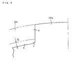
- a driving clutch plate 101 used in a power transmitting apparatus of the prior art has a substantially annular configuration and is formed with a plurality of projections 101a projected radially outward from the periphery of the annular body at an equidistant each other.
- the driving clutch plate 101 usually has as shown in Fig. 6 a linear projected wall surface "a” forming an upstanding surface of the projections 101a and adapted to be engaged with a clutch housing 102, a peripheral surface "b" of the substantially annular body, and a connecting surface "c" having an arcuate configuration of a predetermined curvature and connecting the projected wall surface "a" and the peripheral surface "b".
- a power transmitting apparatus with all the features of the preamble of claim 1 is known from FR-A-890 310 .
- the clutch plates shown in this prior art have projections, the protected wall surfaces of which are radially widened towards their ends. This leads to a stress concentration in the bottom areas of those projections.
- a multiple disc brake assembly is known from EP-A1-1234 993 , wherein the planar plates of this assembly having projections arranged in the planes of the plates.
- the peripheral surfaces of the plates and the projections respectively are connected by means of connecting surfaces, whereby the connecting surfaces are smoothly merged into the peripheral surface of the projections and from an undercut radially inward in respect to the peripheral surfaces of the plates at the same time.
- the connecting surfaces comprise two surface parts having different curvatures.
- an object of the present invention to provide a power transmitting apparatus which can simultaneously achieve the reduction in radial size and the improvement of strength of the driving clutch plate. Moreover, the stress concentration in the driving clutch plate should be reduced.
- a power transmitting apparatus comprising a clutch housing rotatable together with an input member; a plurality of driving clutch plates each having projections projected radially outward from the periphery of a body of the driving clutch plate for engaging the clutch housing to rotate together with it; a clutch member connected to an output member and having a plurality of driven clutch plates alternately arranged between the driving clutch plates; and a pressure plate mounted on the clutch member moveably in an axial direction of the clutch member for carrying out the pressure-contact or release of the driving clutch plates relative to the driven clutch plates via the axial movement of the driving clutch plates relative to the clutch member where a rotational force inputted to the input member can be transmitted to or cut off from the output member via the pressure-contact or release between the driving clutch plates and driven clutch plates, wherein each of the driving clutch plates has a peripheral surface, projected wall surfaces of the projections, and connecting surfaces each connecting each of the projected wall surfaces and the peripheral surface, and that each of the connecting
- the connecting surfaces have first and second connecting concave surfaces comprising curvatures different from each other.
- a power transmitting apparatus of a first embodiment of the present invention is mounted on a vehicle such as a four wheel driving vehicle for arbitrarily transmit or cut off the driving force of an engine and transmission to or from front wheels.
- the power transmitting apparatus of the present invention comprises a clutch housing 2 on which a gear 1 as an input member is mounted, a clutch member 4 connected to a shaft 3 as an output member, a pressure plate 5 mounted on the clutch member 4 at the right end (in view of Fig. 1 ) thereof, driving clutch plates 6 connected to the clutch housing 2, and driven clutch plates 7 connected to the clutch member 4.
- the gear 1 is rotated around the shaft 3 by a driving force (rotational force) transmitted from the engine and connected to the clutch housing 2 via rivets 8 etc.
- the clutch housing 2 is a cylindrical casing member opened at the right end thereof and provided with a plurality of driving clutch plates 6 on the inner peripheral surface thereof.
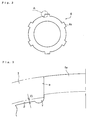
- Each of the driving clutch plates 6 is formed as a substantially annular plate member and engaged with the clutch housing 2 and rotated together therewith.
- the clutch member 4 is formed as a cylindrical casing member opened at the right end thereof and adapted to be received within the clutch housing 2.
- the shaft 3 passes through the center of the clutch member 4 and is connected thereto via a spline connection and thus is rotated by the clutch member 4.
- Axially extending splines are formed on the outer peripheral surface of the clutch member 4 and the driven clutch plates 7 are fitted on the splines.
- driven clutch plates 7 are alternately arranged with the driving clutch plates 6 so that the clutch plates 6 and 7 adjacent each other can be pressure-contacted or released. That is, both clutch plates 6 and 7 are allowed to be slid axially of the clutch member 4 and thus pressure-contacted each other when pushed by the pressure plate 5 toward a left direction (in view of Fig. 1 ) so that the rotational force can be transmitted to the clutch member 4 and the shaft 3. On the contrary, when releasing the pressure of the pressure plate 5, they are also released each other and the clutch member 4 cannot follow the rotation of the clutch housing 2 and is stopped so that no power cannot be transmitted to the shaft 3.
- release of the clutch plates 6 and 7 means a condition where the pressure-contact is lost and thus the clutch member 4 does not follow the rotation of the clutch housing 2 (i.e. a condition where the driving clutch plates 6 slide on the driven clutch plates 7) and thus it is out of the question whether there is any clearance between the clutch plates 6 and 7.
- the pressure plate 5 has a substantially disc configuration such as closing the opening (the right end) of the clutch member 4 and is normally urged toward a left direction by the clutch spring S. That is, the urging of the pressure plate 5 is achieved by the clutch spring S arranged between a boss portion 4b projected from the clutch member 4 and extending through the pressure plate 5 and a head of a bolt B screwed in the boss portion 4b.
- the pressure-contact force between the driving and driven clutch plates 6 and 7 can be released when a driver of vehicle operates to move a push rod 9 toward a right direction (in view of Fig. 1 ) so as to move the pressure plate 5 toward a right direction against the urging force of the clutch spring S.
- the pressure-contacting force between the driving and driven clutch plates 6 and 7 is released, the rotational force inputted to the gear 1 and the clutch housing 2 is cut off and thus not transmitted to the shaft 3. That is, the pressure-contact or the release between the plates 6 and 7 can be achieved by the axial movement of the push rod 9 and accordingly the pressure plate 5.
- the pressure plate 5 is formed with several stopper portions 5b projected therefrom for limit rotation of the pressure plate 5 relative to the clutch member 4.
- Each stopper portion 5b has a projected configuration and is fitted in a recess 4a formed on the inner peripheral surface of the clutch member 4 to limit the relative rotation between the pressure plate 5 and the clutch member 4.
- the driving clutch plate 6 of the prior art is formed with a plurality of projections 6a projected radially outward from the periphery of the driving clutch plate 6 and adapted to be engaged with the clutch housing 2 in the rotational direction.
- the encircled portion is formed by a peripheral surface ⁇ of the body of the driving clutch plate 6, a projected wall surface ⁇ forming an upstanding surface of the projections 6a, and a connecting surface ⁇ connecting the projected wall surface ⁇ and the peripheral surface ⁇ .
- the connecting surface ⁇ extends radially inward from the periphery ⁇ of the driving clutch plate 6 and forms a notch i.e. an undercut at the root of the projection 6a which is recessed radially inward from the periphery ⁇ of the driving clutch plate 6.
- the connecting surface is an arcuate surface smoothly merged into the projected wall surface ⁇ .
- the connecting surface ⁇ is formed as the undercut surface, it is possible to adopt a smaller curvature (i.e. larger radius of curvature) as compared with the connecting surface "c" without any undercut of the prior art ( Fig. 6 ) having a large curvature (i.e. small radius of curvature) and thus to reduce the stress concentration. This improves the strength of the driving clutch plate 6.
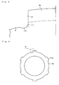
- Fig. 4 shows a preferred embodiment of the driving clutch plate of the present invention.
- the connecting surface comprises a first connecting surface ⁇ 1 extending from the bottom end of the projected wall surface ⁇ and having a predetermined curvature, and a second connecting surface ⁇ 2 extending from the first connecting surface ⁇ 1 and having another predetermined curvature different from that of the first connecting surface ⁇ 1. Also in this case, it is necessary that the second connecting surface ⁇ 2 extends radially inward from the periphery ⁇ of the driving clutch plate and forms an undercut.
- the boundary between the connecting surface ⁇ or first connecting surface ⁇ 1 and the projected wall surface ⁇ is smoothly connected and does not form any angle. If any angle is formed therein, it is preferable that it is an obtuse angle. When any obtuse angle is formed, it is necessary to extend the position of the boundary on the wall surface ⁇ radially inward toward the periphery P in order to reduce the size in radial direction of the power transmitting apparatus.
- the term "smoothly connected" used herein includes meanings not only the case wherein no angle is formed in the boundary but the case wherein an obtuse angle is formed when the wall surface ⁇ is extended radially inward.
- the power transmitting apparatus of the present invention can be applied to a power transmitting apparatus of multiple disc clutch type used to any kinds of vehicles such as a motorcycle, a three or four wheeled buggy, and machines for multiple use.
- the power transmitting apparatus of the present invention can be applied to those having other functions or other outline configurations if the power transmitting apparatus is that where the connecting surface is arcuate surface smoothly connected to the projected wall surface and formed as an undercut extending radially inward from the periphery of the driving clutch plate.
Landscapes
- Engineering & Computer Science (AREA)
- General Engineering & Computer Science (AREA)
- Mechanical Engineering (AREA)
- Mechanical Operated Clutches (AREA)
- Hydraulic Clutches, Magnetic Clutches, Fluid Clutches, And Fluid Joints (AREA)
- Transmitters (AREA)
Claims (5)
- Kraftübertragungsvorrichtung, die Folgendes umfasst: ein Kupplungsgehäuse (2), das zusammen mit einem Antriebselement (1) drehbar ist; mehrere Antriebskupplungslamellen (6), die jeweils Vorsprünge (6a) aufweisen, die vom Umfang der Antriebskupplungslamelle (6) radial nach außen hervorstehen, um das Kupplungsgehäuse (2) in Eingriff zu nehmen, um sich zusammen mit ihm zu drehen; ein Kupplungselement (4), das mit einem Abtriebselement (3) verbunden ist und mehrere angetriebene Kupplungslamellen (7) aufweist, die im Wechsel zwischen den Antriebskupplungslamellen (6) angeordnet sind; und eine Druckplatte (5), die so an dem Kupplungselement (4) montiert ist, dass sie sich in einer axialen Richtung des Kupplungselements (4) bewegen kann, um den Druckkontakt oder das Lösen der Antriebskupplungslamellen (6) relativ zu den angetriebenen Kupplungslamellen (7) über die axiale Bewegung der Antriebskupplungslamellen (6) relativ zu dem Kupplungselement (4) auszuführen, wobei eine an das Antriebselement (1) angelegte Rotationskraft über den Druckkontakt oder das Lösen zwischen den Antriebskupplungslamellen (6) und den angetriebenen Kupplungslamellen (7) an das Abtriebselement (3) übertragen oder von dem Abtriebselement (3) abgekoppelt werden kann, wobei jede der Antriebskupplungslamellen (6) im Wesentlichen planar ist und eine Ebene definiert, wobei sich die Vorsprünge (6a) in dieser Ebene befinden, wobei jede Antriebskupplungslamellen (6) eine Umfangsfläche (β), ein Paar hervorstehender Wandflächen (α) der Vorsprünge (6a) und ein Paar Verbindungsflächen (γ), eine auf jeder Seite des Vorsprung (6a), aufweist, wobei jede Verbindungsfläche (γ) die hervorstehenden Wandflächen (α) und die Umfangsfläche (β) verbindet, und wobei jede der Verbindungsflächen (γ) eine Bogenfläche ist, die sanft in die hervorstehende Wandfläche (α) übergeht und eine Hinterschneidung bildet, die vom Umfang (β) der Antriebskupplungslamelle (6) aus radial nach innen vertieft ist, dadurch gekennzeichnet, dass die Verbindungsfläche (γ) eine erste konkave Verbindungsfläche (γ1) umfasst, die sich vom unteren Ende der hervorstehenden Wandfläche (α) erstreckt und eine vorgegebene Krümmung aufweist, und eine zweite konkave Verbindungsfläche (γ2) umfasst, die sich von der ersten konkaven Verbindungsfläche (γ1) erstreckt und ebenfalls eine vorgegebene Krümmung aufweist, die sich von der Krümmung der ersten konkaven Verbindungsfläche (γ1) unterscheidet.
- Kraftübertragungsvorrichtung nach Anspruch 1, wobei eine Welle (3) durch die Mitte des Kupplungselements (4) hindurch verläuft und mit diesem über ein Keilprofil verbunden ist, um die Welle (3) durch das Kupplungselement (4) anzutreiben.
- Kraftübertragungsvorrichtung nach Anspruch 1 oder 2, wobei die Druckplatte (5) eine im Wesentlichen scheibenförmige Konfiguration aufweist.
- Kraftübertragungsvorrichtung nach einem der Ansprüche 1 bis 3, wobei die Druckplatte (5) mit mehreren Stopperabschnitten (5b) ausgebildet ist, die von dort hervorstehen, um eine Rotation der Druckplatte (5) relativ zu der Kupplungselement (4) zu begrenzen.
- Kraftübertragungsvorrichtung nach Anspruch 4, wobei jeder Stopperabschnitt (5b) als ein hervorstehendes Element konfiguriert ist und in eine Vertiefung (4a) eingepasst ist, die in der Innenumfangsfläche des Kupplungselements (4) ausgebildet ist.
Applications Claiming Priority (2)
| Application Number | Priority Date | Filing Date | Title |
|---|---|---|---|
| JP2004045616A JP2005233359A (ja) | 2004-02-23 | 2004-02-23 | 動力伝達装置 |
| JP2004045616 | 2004-02-23 |
Publications (2)
| Publication Number | Publication Date |
|---|---|
| EP1566558A1 EP1566558A1 (de) | 2005-08-24 |
| EP1566558B1 true EP1566558B1 (de) | 2010-04-07 |
Family
ID=34709171
Family Applications (1)
| Application Number | Title | Priority Date | Filing Date |
|---|---|---|---|
| EP05003621A Expired - Lifetime EP1566558B1 (de) | 2004-02-23 | 2005-02-19 | Apparat zur Leistungsübertragung |
Country Status (6)
| Country | Link |
|---|---|
| US (1) | US7237664B2 (de) |
| EP (1) | EP1566558B1 (de) |
| JP (1) | JP2005233359A (de) |
| CN (1) | CN1661255A (de) |
| AT (1) | ATE463679T1 (de) |
| DE (1) | DE602005020381D1 (de) |
Families Citing this family (7)
| Publication number | Priority date | Publication date | Assignee | Title |
|---|---|---|---|---|
| JP4545489B2 (ja) * | 2004-06-01 | 2010-09-15 | アイシン・エィ・ダブリュ株式会社 | クッションプレート |
| JP4917754B2 (ja) * | 2005-02-10 | 2012-04-18 | 日本発條株式会社 | 皿ばね |
| JP2007120520A (ja) * | 2005-10-25 | 2007-05-17 | Honda Motor Co Ltd | ダンパスプリングを備えるクラッチ |
| JP4344396B2 (ja) * | 2007-09-12 | 2009-10-14 | 株式会社エフ・シー・シー | 動力伝達装置 |
| JP5667529B2 (ja) | 2011-07-05 | 2015-02-12 | 本田技研工業株式会社 | クラッチ装置 |
| US9482287B2 (en) | 2014-02-12 | 2016-11-01 | Ford Global Technologies, Llc | Pressure plate stress-relief grooves for a friction element assembly in a transmission of a motor vehicle and associated method |
| JP6893737B2 (ja) * | 2017-09-01 | 2021-06-23 | ジヤトコ株式会社 | 動力伝達装置及び摩擦締結要素 |
Citations (1)
| Publication number | Priority date | Publication date | Assignee | Title |
|---|---|---|---|---|
| EP1234993A1 (de) * | 2001-02-23 | 2002-08-28 | Dana Italia S.p.A | Radnabe mit integriertem Planetengetriebe und Lamellenbremse |
Family Cites Families (10)
| Publication number | Priority date | Publication date | Assignee | Title |
|---|---|---|---|---|
| US1172146A (en) * | 1913-02-28 | 1916-02-15 | Packard Motor Car Co | Clutch. |
| FR890310A (fr) | 1942-01-22 | 1944-02-04 | Zahnradfabrik Friedrichshafen | Lame de friction à fentes radiales partant de l'intérieur et de l'extérieur pour embrayages électro-magnétiques |
| US3094194A (en) * | 1961-01-23 | 1963-06-18 | Lambert & Brake Corp | Friction device |
| US3250349A (en) * | 1964-03-20 | 1966-05-10 | American Brake Shoe Co | Disc brake |
| US4071360A (en) * | 1976-01-19 | 1978-01-31 | Borg-Warner Corporation | Method of forming a friction disc member |
| ES496049A0 (es) | 1980-10-17 | 1982-05-01 | Martinez Parra Jose | Sistema de produccion de energia electrica,mediante el aprovechamiento y control de la energia potencial de las aguas del mar |
| JPS5986716A (ja) * | 1982-11-08 | 1984-05-19 | Yamaha Motor Co Ltd | 多板式クラツチ |
| JPS59181340U (ja) * | 1983-05-20 | 1984-12-04 | 不二化学工業株式会社 | 多板式クラツチ装置 |
| US4863001A (en) * | 1987-02-18 | 1989-09-05 | The Bf Goodrich Company | Brake apparatus |
| US5094331A (en) * | 1988-03-18 | 1992-03-10 | Honda Giken Kogyo Kabushiki Kaisha | Wet-type multiplate clutch |
-
2004
- 2004-02-23 JP JP2004045616A patent/JP2005233359A/ja active Pending
-
2005
- 2005-02-19 DE DE602005020381T patent/DE602005020381D1/de not_active Expired - Lifetime
- 2005-02-19 EP EP05003621A patent/EP1566558B1/de not_active Expired - Lifetime
- 2005-02-19 AT AT05003621T patent/ATE463679T1/de active
- 2005-02-22 US US11/062,945 patent/US7237664B2/en not_active Expired - Lifetime
- 2005-02-23 CN CN2005100088070A patent/CN1661255A/zh active Pending
Patent Citations (1)
| Publication number | Priority date | Publication date | Assignee | Title |
|---|---|---|---|---|
| EP1234993A1 (de) * | 2001-02-23 | 2002-08-28 | Dana Italia S.p.A | Radnabe mit integriertem Planetengetriebe und Lamellenbremse |
Also Published As
| Publication number | Publication date |
|---|---|
| ATE463679T1 (de) | 2010-04-15 |
| JP2005233359A (ja) | 2005-09-02 |
| DE602005020381D1 (de) | 2010-05-20 |
| US20050183921A1 (en) | 2005-08-25 |
| EP1566558A1 (de) | 2005-08-24 |
| US7237664B2 (en) | 2007-07-03 |
| CN1661255A (zh) | 2005-08-31 |
Similar Documents
| Publication | Publication Date | Title |
|---|---|---|
| EP1555450B1 (de) | Leistungsübertragungsvorrichtung | |
| US10670087B2 (en) | Power transmitting apparatus | |
| EP2037142B1 (de) | Kraftübertragungsvorrichtung | |
| US7721862B2 (en) | Power transmitting apparatus | |
| EP2039950B1 (de) | Kraftübertragungsvorrichtung | |
| EP1655502B1 (de) | Apparat zur Leistungsübertragung | |
| EP1566558B1 (de) | Apparat zur Leistungsübertragung | |
| US11149799B2 (en) | Power transmission device | |
| JP6903020B2 (ja) | 動力伝達装置 | |
| US7810236B2 (en) | Method for manufacturing a power transmitting apparatus | |
| JP2008039192A (ja) | 動力伝達装置 | |
| JP4364170B2 (ja) | 動力伝達装置 |
Legal Events
| Date | Code | Title | Description |
|---|---|---|---|
| PUAI | Public reference made under article 153(3) epc to a published international application that has entered the european phase |
Free format text: ORIGINAL CODE: 0009012 |
|
| AK | Designated contracting states |
Kind code of ref document: A1 Designated state(s): AT BE BG CH CY CZ DE DK EE ES FI FR GB GR HU IE IS IT LI LT LU MC NL PL PT RO SE SI SK TR |
|
| AX | Request for extension of the european patent |
Extension state: AL BA HR LV MK YU |
|
| 17P | Request for examination filed |
Effective date: 20050810 |
|
| AKX | Designation fees paid |
Designated state(s): AT DE FR GB IT |
|
| 17Q | First examination report despatched |
Effective date: 20060131 |
|
| GRAP | Despatch of communication of intention to grant a patent |
Free format text: ORIGINAL CODE: EPIDOSNIGR1 |
|
| GRAS | Grant fee paid |
Free format text: ORIGINAL CODE: EPIDOSNIGR3 |
|
| GRAA | (expected) grant |
Free format text: ORIGINAL CODE: 0009210 |
|
| AK | Designated contracting states |
Kind code of ref document: B1 Designated state(s): AT DE FR GB IT |
|
| REG | Reference to a national code |
Ref country code: GB Ref legal event code: FG4D |
|
| REF | Corresponds to: |
Ref document number: 602005020381 Country of ref document: DE Date of ref document: 20100520 Kind code of ref document: P |
|
| PLBE | No opposition filed within time limit |
Free format text: ORIGINAL CODE: 0009261 |
|
| STAA | Information on the status of an ep patent application or granted ep patent |
Free format text: STATUS: NO OPPOSITION FILED WITHIN TIME LIMIT |
|
| 26N | No opposition filed |
Effective date: 20110110 |
|
| GBPC | Gb: european patent ceased through non-payment of renewal fee |
Effective date: 20110219 |
|
| REG | Reference to a national code |
Ref country code: FR Ref legal event code: ST Effective date: 20111102 |
|
| PG25 | Lapsed in a contracting state [announced via postgrant information from national office to epo] |
Ref country code: FR Free format text: LAPSE BECAUSE OF NON-PAYMENT OF DUE FEES Effective date: 20110228 |
|
| PG25 | Lapsed in a contracting state [announced via postgrant information from national office to epo] |
Ref country code: GB Free format text: LAPSE BECAUSE OF NON-PAYMENT OF DUE FEES Effective date: 20110219 |
|
| PGFP | Annual fee paid to national office [announced via postgrant information from national office to epo] |
Ref country code: IT Payment date: 20210112 Year of fee payment: 17 |
|
| PGFP | Annual fee paid to national office [announced via postgrant information from national office to epo] |
Ref country code: AT Payment date: 20210125 Year of fee payment: 17 Ref country code: DE Payment date: 20210209 Year of fee payment: 17 |
|
| REG | Reference to a national code |
Ref country code: DE Ref legal event code: R119 Ref document number: 602005020381 Country of ref document: DE |
|
| REG | Reference to a national code |
Ref country code: AT Ref legal event code: MM01 Ref document number: 463679 Country of ref document: AT Kind code of ref document: T Effective date: 20220219 |
|
| PG25 | Lapsed in a contracting state [announced via postgrant information from national office to epo] |
Ref country code: AT Free format text: LAPSE BECAUSE OF NON-PAYMENT OF DUE FEES Effective date: 20220219 |
|
| PG25 | Lapsed in a contracting state [announced via postgrant information from national office to epo] |
Ref country code: DE Free format text: LAPSE BECAUSE OF NON-PAYMENT OF DUE FEES Effective date: 20220901 |
|
| PG25 | Lapsed in a contracting state [announced via postgrant information from national office to epo] |
Ref country code: IT Free format text: LAPSE BECAUSE OF NON-PAYMENT OF DUE FEES Effective date: 20220219 |