EP1566552B1 - Fluid pressure cylinder - Google Patents
Fluid pressure cylinder Download PDFInfo
- Publication number
- EP1566552B1 EP1566552B1 EP03812272A EP03812272A EP1566552B1 EP 1566552 B1 EP1566552 B1 EP 1566552B1 EP 03812272 A EP03812272 A EP 03812272A EP 03812272 A EP03812272 A EP 03812272A EP 1566552 B1 EP1566552 B1 EP 1566552B1
- Authority
- EP
- European Patent Office
- Prior art keywords
- fluid pressure
- cylinder
- piston
- cylinder body
- movable stopper
- Prior art date
- Legal status (The legal status is an assumption and is not a legal conclusion. Google has not performed a legal analysis and makes no representation as to the accuracy of the status listed.)
- Expired - Lifetime
Links
- 239000012530 fluid Substances 0.000 title claims description 47
- 230000004048 modification Effects 0.000 description 4
- 238000012986 modification Methods 0.000 description 4
- 230000004323 axial length Effects 0.000 description 2
- 230000000903 blocking effect Effects 0.000 description 1
- 238000009434 installation Methods 0.000 description 1
- 238000012856 packing Methods 0.000 description 1
- 239000004065 semiconductor Substances 0.000 description 1
Images


Classifications
-
- F—MECHANICAL ENGINEERING; LIGHTING; HEATING; WEAPONS; BLASTING
- F15—FLUID-PRESSURE ACTUATORS; HYDRAULICS OR PNEUMATICS IN GENERAL
- F15B—SYSTEMS ACTING BY MEANS OF FLUIDS IN GENERAL; FLUID-PRESSURE ACTUATORS, e.g. SERVOMOTORS; DETAILS OF FLUID-PRESSURE SYSTEMS, NOT OTHERWISE PROVIDED FOR
- F15B15/00—Fluid-actuated devices for displacing a member from one position to another; Gearing associated therewith
- F15B15/20—Other details, e.g. assembly with regulating devices
- F15B15/24—Other details, e.g. assembly with regulating devices for restricting the stroke
Definitions
- the present invention relates to a fluid pressure cylinder including a rod to reciprocate by fluid pressure, according to the preamble of claim 1.
- Such a fluid pressure cylinder is known from US 2 605 748 .
- the conventional fluid pressure cylinder serves as a reciprocating actuator activated by air pressure or hydraulic pressure.
- the fluid pressure cylinder comprises a cylinder body having a cylinder chamber therein, a piston reciprocally provided in the cylinder chamber and separating the cylinder chamber into a forward fluid pressure chamber and a backward fluid pressure chamber, and a piston rod fixed to the end face of the piston and projecting externally from the cylinder body.
- One of the fluid pressure chambers is supplied with the fluid pressure and the other of the fluid pressure chamber is vented so that the piston and the piston rod are pressed to move to the opposite side.
- the position at which the piston is stopped moving by contacting a cover or stopper provided on the end of the cylinder body is a stroke end position of the forward side or a stroke end position of the backward side.
- the cylinder body is fixed to the equipment body.
- an adjusting rod projected from the cylinder body to the opposite side of the piston rod is fixed to the piston, and the axial position of an adjusting nut screwed into the circumference of the projecting portion is changed so that the position at which the adjusting nut is contacted the rear end of the cylinder body, i.e. the stroke end position of the forward side of the piston rod is adjusted.
- an adjusting bolt is screwed into the end of the backward side of the cylinder body and further screwed to insert into the cylinder body to change the depth of the adjusting bolt in the cylinder body so that the position at which the piston is contacted the leading edge of the adjusting bolt, i.e., the stoke end position of the backward side of the piston rod is adjusted.
- the object of the present invention is to provide a fluid pressure cylinder in which at least one of the stroke end position of the forward side or the stroke end position of the backward side of the piston rod can be adjusted without having the axially long adjustment member.
- the object of the present invention is to provide a fluid pressure cylinder in which at least one of the stroke end position of the forward side or the stroke end position of the backward side of the piston rod can be adjusted even if the cylinder is a double rod type.
- the fluid pressure cylinder when a rotating knob is rotated, a movable stopper is screwed into thereby the axial position can be changed and also the stroke end position and the moving stroke of the piston can be adjusted.
- the total length for the fixed portion combined the rotating knob with the cylinder body is not changed during adjusting.
- the fluid pressure cylinder can be installed in a small space. Further, the fluid pressure cylinder according to the present invention can be applied to the configuration such that the stroke end position of both of the forward side and the backward side are adjusted, and a double rod type.
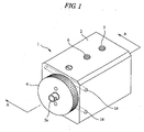
- FIG. 1 is a general perspective view of the fluid pressure cylinder according to one embodiment.
- a rotating knob 4 formed of approximate circular disk is rotatably provided on the front surface of a cylinder body 2 formed of approximate rectangular parallelepiped as shown FIG.1 .
- a piston rod 5a externally projecting through the rotating knob 4 is slidably mounted in the cylinder body 2.
- Two supply and discharge ports 6 and 7 formed on the upper surface of the cylinder body 2 as shown FIG.1 are controllably supplied with compressed air, respectively so that the fluid pressure cylinder 1 serves as a double acting air cylinder to reciprocate the piston rod 5a.
- the direction to which the piston rod projects from the cylinder body 2 (left hand in each figure) is the forward direction of the piston rod 5a, alternatively, the direction into which the piston rod draws (right hand in each figure) is the backward direction of the piston rod 5a.
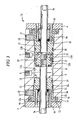
- FIGs.2A and 2B are sectional views along the A-A line of FIG.1 when the piston rod 5a is located at the inmost stroke end position in the backward side.
- FIG.2A is a sectional view when the movable stopper is located at the forward limit.
- FIG.2B is a sectional view when the movable stopper is located at the backward limit.
- a piston receiving hole 8 is formed in a longitudinal direction in the cylinder body 2 as shown FIG.2A and FIG.2B .
- a cylinder chamber 11 is formed in the space in which a movable stopper 9 at the forward side and a cylinder-head cover 10 at the backward side are provided.
- a piston 12 is axially and reciprocally mounted in the cylinder chamber 11.
- the inside of the cylinder chamber 11 is separated into a backward fluid pressure chamber 11a and a forward fluid pressure chamber 11b by the piston 12.
- a rotating knob 4 formed of approximate circular disk is provided on the end of the forward side of the cylinder body 2.
- the piston rod 5a fixed to the end face of the forward side of the piston 12 is slidably supported through the center of the rotating knob 4 and the movable stopper 9.
- the piston 12 is formed of approximate cylinder.
- the outer diameter of a forward end 12a and a backward end 12b of the piston 12 is slightly smaller than a slidable middle portion 12b therebetween.
- the slidable middle portion 12b is fitted into and slidably contact with the piston receiving hole 8.
- the forward end 12a and the backward end 12c are not contact with the inner surface of the piston receiving hole 8.
- Wear rings 12d are mounted on each circumference of the forward end 12a and the backward end 12c. The wear rings 12d sandwich the slidable middle portion 12b therebetween.
- the wear rings 12d can maintain to be in fluid communication with the backward fluid pressure chamber 11a and the forward fluid pressure chamber 11b without blocking up the supply and discharge ports 6 and 7 even if those axial position is same as each of the supply and discharge ports 6 and 7 while the wear rings 12d are in slidably contact with the piston receiving hole 8.
- a female screw 8a is provided on the inner circumference of the forward side of the piston receiving hole 8 thereby the movable stopper 9 is screwed into the piston receiving hole 8.
- the movable stopper 9 rotates around the axis to screw into thereby to axially reciprocate.
- a cylinder-head cover 10 is fitted into the backward side of the piston receiving hole 8.
- the piston 12 is located at the stroke end of the forward side while its end face of the forward side is contact with the end face of the backward side of the movable stopper 9.
- the piston 12 is located at the stroke end of the backward side while its end face of the backward side is contact with the end face of the forward side of the cylinder-head cover 10.
- a retaining groove 13 is formed on the concentric circle slightly outer than the opening of the piston receiving hole 8 on the end face of the forward side of the cylinder body 2, and an engaging groove 13a is formed on the side wall of the outer circumference.
- a cylindrical edge portion 4b having a flange 4a fitted into the retaining groove 13 is formed on the end face of the backward side of the rotating knob 4.
- a parallel pin or spring pin 14 is fitted into the outer circumference of the cylindrical edge portion 4b and the cylindrical edge portion 4b is pressed to insert into the retaining groove 13 so that the parallel pin or spring pin 14 is engaged with the inner engaging groove 13 thereby the whole rotating knob 4 is rotatably attached to the cylinder body 2.
- a through-hole 15 through which the piston rod 5a is passed is formed at the shaft center of the rotating knob 4 and the movable stopper 9.
- Rotation transmitting pins 16 are projected at two positions around the through-hole 15 on the end face of the backward side of the rotating knob 4.
- Rotation transmitting holes 9a are formed at the corresponding two positions on the end face of the forward side of the movable stopper 9.
- Each of the rotation transmitting pins 16 is slidably inserted into the rotation transmitting holes 9a.
- a screw hole 17 is formed on the upper surface of the cylinder body 2 in the same axial position as the forward end of the movable stopper 9 as shown FIG.2B .
- a stopper set screw 18 is screwed into the screw hole 17.
- the supply and discharge ports 6 and 7 are formed on the upper surface of the cylinder body 2 as shown FIG.2B .
- the compressed air is supplied and discharged to/from the backward fluid pressure chamber 11a and the forward fluid pressure chamber 11b through the supply and discharge ports 6 and 7.
- the supply and discharge port 6 in communication with the backward fluid pressure chamber 11a is located at the same axial position as a chamfered portion 9b formed on the outer circumference of the end of the backward side of the movable stopper 9. Thereby the supply and discharge port 6 is in sure communication with the backward fluid pressure chamber 11a even if the movable stopper 9 is located at the backward limit.
- the axial length X of the forward end 12a having the small diameter of the piston 12 is approximately equal to the movable length Y (stroke adjustment length) of the movable stopper 9.
- the supply and discharge port 7 in communication with the forward fluid pressure chamber 11b is located at the same axial position as backward end 12c having the small diameter. Thereby the supply and discharge port 7 is not blocked up by the slidable middle portion 12b of the piston 12 consistently maintained to be in communication with the backward fluid pressure chamber 11b.
- An O ring 19 is provided on the outer circumference of the movable stopper 9 and the cylinder-head cover 10.
- a seal ring 20 is provided on the outer circumference of the slidable middle portion 12b of the piston 12.
- a packing 21 is provided in the through-hole 15 of the movable stopper 9.
- an axle member is composed of the piston 12 and the piston rod 5a, and a stroke end adjusting mechanism is composed of the rotating knob 4, the rotation transmitting pins 16 and the movable stopper 9.
- the rotating knob 4 is rotated to rotate the movable stopper 9 through the two rotation transmitting pins 16 so that the movable stopper 9 is screwed and backwardly moved.
- the rotation transmitting pins 16 fixed to the rotating knob 4 are kept to be inserted while it is in slidably connect with the rotation transmitting hole 9a of the movable stopper 9 so that the rotation of the rotating knob 4 can be transmitted to the movable stopper 9.
- the movable stopper 9 is backwardly moved so that the axial position of the end face of the backward side thereof, i.e. the stroke end position of the forward side of the piston 12 is also backwardly moved and the moving stroke of the piston 12 is shortened therewith.
- the stroke end position of the forward side and the moving stroke of the piston 12 can be adjusted by rotating the rotating knob 4 to change the axial position of the movable stopper 9. Additionally, the total length of the fixed portion combined the rotating knob 4 with the cylinder body 2 is not changed during the adjustment. Further, the axially long adjustment member such as an adjusting rod is not provided at the end the backward side of the cylinder body 2 thereby to be installed in a small space.
- FIG.3 is a sectional view of the fluid pressure cylinder 31 according to the modification of the present embodiment.
- a stroke adjusting mechanism is provided at both end of the cylinder body 32 of the fluid pressure cylinder 31 and a piston rod 5a and 5b are provided at both end of the piston 12 thereby a double rod cylinder is formed.
- both side of the axial position of the stroke end positions of the piston 12 can be independently adjusted but also the whole axial position can be adjusted without changing the stroke length by simultaneously moving two movable stoppers 9 and 33 in the same direction.
- both of the stroke end adjusting mechanism and the piston rods 5a and 5b are provided at the forward side and the backward side in the modification, however, either of the stroke end adjusting mechanism or the piston rods 5a and 5b may be provided at the both of the forward side and the backward side.
- the stroke end adjusting mechanism is provided at both ends of the cylinder body 32 and the piston rod 5a is provided at only the forward side of the cylinder body 32.
- the stroke adjusting mechanism is provided at only the forward side of the cylinder body 32 and the piston rods 5a and 5b are provided at both of the forward side and the backward side.
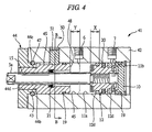
- FIG. 4 is a sectional view of the fluid pressure cylinder according to another embodiment.
- FIG. 5 is a sectional view along the B-B line of FIG.4 .
- the same reference letters and numerals are used to designate the same or similar components as those of the fluid pressure cylinder 1 of FIG.2A and FIG.2B as shown in FIG.4 and FIG. 5
- an engaging groove 43 is formed on the inner circumference of the forward side of a piston receiving hole 45.
- a cylindrical edge portion 44b to be fitted into the piston receiving hole 45 is formed on the end face of the backward side of a rotating knob 44.
- a parallel pin or spring pin 47 is fitted into an engaging groove 44c formed on the outer circumference of the cylindrical edge portion 44b and the cylindrical edge portion 44b is pressed to insert into the piston receiving hole 45 so that the parallel pin or spring pin 47 is engaged with the engaging groove 44c at the cylindrical edge portion 44b and the engaging groove 43 into the piston receiving hole 45.
- the whole rotating knob 44 is rotatably attached to a cylinder body 42.
- a female screw 44d having the larger diameter than the piston rod 5a is formed at the center of the rotating knob 44.
- a movable stopper 48 The forward side portion of a movable stopper 48 is screwed into the rotating knob 44 and the backward side portion of that is slidably mounted in the piston receiving hole 45.
- An engaging groove 49 is formed on the upper side surface of the movable stopper 48 as shown FIG.4 and FIG.5 .
- a stopper set screw 51 as a rotation stopping member is screwed into a screw hole 50 formed on the upper surface of the cylinder 42 to engage with the engaging groove 49 as shown FIG 4 and FIG.5 .
- the movable stopper 48 is engaged with the stopper set screw 51 thereby not to rotate about the axis but only axially move. Additionally, the movable stopper 48 is certainly screwed to axially reciprocate by rotating the rotating knob 44.
- the stroke end position of the forward side and the moving stroke of the piston 12 can be adjusted by changing the axial position of the movable stopper 48 as well as the above mentioned one embodiment. Additionally, the total length of the fixed portion is not changed during adjusting thereby to be installed in a small space. Further, the stroke adjusting mechanism can be provided at not only the end of the forward side of the cylinder body 42 but also the end of the backward side thereof.
- the piston rod 5a may be provided at both end of the piston 12 to be served as a double rod cylinder.
- the movable stopper 48 can be fixed by tightening up the stopper set screw 51.
- the fluidpressure for the operation control may be hydraulic pressure such as hydraulic fluid instead of air pressure by compressing the air.
- the present invention may be applied to a cylinder body formed of circular cross section.
- the fluid pressure cylinder according to the present invention can be effectively applied to an actuator used for such as an equipment to ccnvey electronic components, e.g. semiconductor chips thereby the stroke end position of both of the forward side and the backward side, or the stroke length of the piston rod therebetween can be optionally adjusted depending on various components in different form.
- an actuator used for such as an equipment to ccnvey electronic components e.g. semiconductor chips
- the stroke end position of both of the forward side and the backward side, or the stroke length of the piston rod therebetween can be optionally adjusted depending on various components in different form.
Landscapes
- Engineering & Computer Science (AREA)
- Physics & Mathematics (AREA)
- Fluid Mechanics (AREA)
- Mechanical Engineering (AREA)
- General Engineering & Computer Science (AREA)
- Actuator (AREA)
Description
- The present invention relates to a fluid pressure cylinder including a rod to reciprocate by fluid pressure, according to the preamble of claim 1.
- Such a fluid pressure cylinder is known from
US 2 605 748 . - The conventional fluid pressure cylinder serves as a reciprocating actuator activated by air pressure or hydraulic pressure. The fluid pressure cylinder comprises a cylinder body having a cylinder chamber therein, a piston reciprocally provided in the cylinder chamber and separating the cylinder chamber into a forward fluid pressure chamber and a backward fluid pressure chamber, and a piston rod fixed to the end face of the piston and projecting externally from the cylinder body.
- One of the fluid pressure chambers is supplied with the fluid pressure and the other of the fluid pressure chamber is vented so that the piston and the piston rod are pressed to move to the opposite side. The position at which the piston is stopped moving by contacting a cover or stopper provided on the end of the cylinder body is a stroke end position of the forward side or a stroke end position of the backward side.
- Usually, when such fluid pressure cylinder is used for equipment, the cylinder body is fixed to the equipment body. However, it may be necessary to optionally adjust the stroke end position of the forward side and the stroke end position of the backward side of the piston rod or the stroke length of the piston rod therebetween relative to the fixed positions of the cylinder body.
- In one conventional single rod fluid pressure cylinder, an adjusting rod projected from the cylinder body to the opposite side of the piston rod is fixed to the piston, and the axial position of an adjusting nut screwed into the circumference of the projecting portion is changed so that the position at which the adjusting nut is contacted the rear end of the cylinder body, i.e. the stroke end position of the forward side of the piston rod is adjusted. Additionally, in another conventional single rod fluid pressure cylinder, an adjusting bolt is screwed into the end of the backward side of the cylinder body and further screwed to insert into the cylinder body to change the depth of the adjusting bolt in the cylinder body so that the position at which the piston is contacted the leading edge of the adjusting bolt, i.e., the stoke end position of the backward side of the piston rod is adjusted.
- In the above mentioned both of the adjustments for the stroke, it was required to take an axially long installation space because long adjustment members such as the adjusting rod and the adjusting bolt are provided on the end of the backward side of the cylinder body. Additionally, it was not be able to be applied to a double rod cylinder having a piston rod to activate in the backward side of the piston.
- The object of the present invention is to provide a fluid pressure cylinder in which at least one of the stroke end position of the forward side or the stroke end position of the backward side of the piston rod can be adjusted without having the axially long adjustment member.
- The object of the present invention is to provide a fluid pressure cylinder in which at least one of the stroke end position of the forward side or the stroke end position of the backward side of the piston rod can be adjusted even if the cylinder is a double rod type.
- In the fluid pressure cylinder according to the present invention, when a rotating knob is rotated, a movable stopper is screwed into thereby the axial position can be changed and also the stroke end position and the moving stroke of the piston can be adjusted. The total length for the fixed portion combined the rotating knob with the cylinder body is not changed during adjusting. Additionally, since the axially long adjustment members are not provided on the end of the backward side of the cylinder body, the fluid pressure cylinder can be installed in a small space. Further, the fluid pressure cylinder according to the present invention can be applied to the configuration such that the stroke end position of both of the forward side and the backward side are adjusted, and a double rod type.
-
-
FIG.1 is a general perspective view of the fluidpressure cylinder 1 according to one embodiment; -
FIGs.2A and 2B are sectional views along the A-A line ofFIG.1 when the piston rod is located at the stroke end of the backward side.FIG. 2A is a sectional view when the movable stopper is located at the forward limit.FIG.2B is a sectional view when the movable stopper is located at the backward limit; -
FIG.3 is a sectional view of the fluidpressure cylinder according to the modification of the embodiment; -
FIG. 4 is a sectional view of the fluid pressure cylinder according to another embodiment; and -
FIG.5 is a sectional view along the B-B line ofFIG.4 . - Hereinafter the preferred embodiments of the present invention are described in detail with reference to the drawings.
-
FIG. 1 is a general perspective view of the fluid pressure cylinder according to one embodiment. A rotatingknob 4 formed of approximate circular disk is rotatably provided on the front surface of acylinder body 2 formed of approximate rectangular parallelepiped as shownFIG.1 . Apiston rod 5a externally projecting through the rotatingknob 4 is slidably mounted in thecylinder body 2. Two supply anddischarge ports cylinder body 2 as shownFIG.1 are controllably supplied with compressed air, respectively so that the fluid pressure cylinder 1 serves as a double acting air cylinder to reciprocate thepiston rod 5a. The direction to which the piston rod projects from the cylinder body 2 (left hand in each figure) is the forward direction of thepiston rod 5a, alternatively, the direction into which the piston rod draws (right hand in each figure) is the backward direction of thepiston rod 5a. -
FIGs.2A and 2B are sectional views along the A-A line ofFIG.1 when thepiston rod 5a is located at the inmost stroke end position in the backward side.FIG.2A is a sectional view when the movable stopper is located at the forward limit.FIG.2B is a sectional view when the movable stopper is located at the backward limit. Apiston receiving hole 8 is formed in a longitudinal direction in thecylinder body 2 as shownFIG.2A and FIG.2B . In thepiston receiving hole 8, acylinder chamber 11 is formed in the space in which amovable stopper 9 at the forward side and a cylinder-head cover 10 at the backward side are provided. Apiston 12 is axially and reciprocally mounted in thecylinder chamber 11. The inside of thecylinder chamber 11 is separated into a backwardfluid pressure chamber 11a and a forwardfluid pressure chamber 11b by thepiston 12. A rotatingknob 4 formed of approximate circular disk is provided on the end of the forward side of thecylinder body 2. Thepiston rod 5a fixed to the end face of the forward side of thepiston 12 is slidably supported through the center of the rotatingknob 4 and themovable stopper 9. - The
piston 12 is formed of approximate cylinder. The outer diameter of aforward end 12a and abackward end 12b of thepiston 12 is slightly smaller than aslidable middle portion 12b therebetween. Theslidable middle portion 12b is fitted into and slidably contact with thepiston receiving hole 8. Theforward end 12a and thebackward end 12c are not contact with the inner surface of thepiston receiving hole 8.Wear rings 12d are mounted on each circumference of theforward end 12a and thebackward end 12c. Thewear rings 12d sandwich theslidable middle portion 12b therebetween. Thewear rings 12d can maintain to be in fluid communication with the backwardfluid pressure chamber 11a and the forwardfluid pressure chamber 11b without blocking up the supply anddischarge ports discharge ports wear rings 12d are in slidably contact with thepiston receiving hole 8. - A
female screw 8a is provided on the inner circumference of the forward side of thepiston receiving hole 8 thereby themovable stopper 9 is screwed into thepiston receiving hole 8. Themovable stopper 9 rotates around the axis to screw into thereby to axially reciprocate. A cylinder-head cover 10 is fitted into the backward side of thepiston receiving hole 8. Thepiston 12 is located at the stroke end of the forward side while its end face of the forward side is contact with the end face of the backward side of themovable stopper 9. Alternatively, thepiston 12 is located at the stroke end of the backward side while its end face of the backward side is contact with the end face of the forward side of the cylinder-head cover 10. - Additionally, a
retaining groove 13 is formed on the concentric circle slightly outer than the opening of thepiston receiving hole 8 on the end face of the forward side of thecylinder body 2, and anengaging groove 13a is formed on the side wall of the outer circumference. - A
cylindrical edge portion 4b having aflange 4a fitted into theretaining groove 13 is formed on the end face of the backward side of the rotatingknob 4. A parallel pin orspring pin 14 is fitted into the outer circumference of thecylindrical edge portion 4b and thecylindrical edge portion 4b is pressed to insert into theretaining groove 13 so that the parallel pin orspring pin 14 is engaged with the innerengaging groove 13 thereby the whole rotatingknob 4 is rotatably attached to thecylinder body 2. - A through-
hole 15 through which thepiston rod 5a is passed is formed at the shaft center of the rotatingknob 4 and themovable stopper 9. Rotation transmittingpins 16 are projected at two positions around the through-hole 15 on the end face of the backward side of the rotatingknob 4.Rotation transmitting holes 9a are formed at the corresponding two positions on the end face of the forward side of themovable stopper 9. Each of the rotation transmittingpins 16 is slidably inserted into therotation transmitting holes 9a. - While the
movable stopper 9 is located at the inmost forward side, ascrew hole 17 is formed on the upper surface of thecylinder body 2 in the same axial position as the forward end of themovable stopper 9 as shownFIG.2B . A stopper setscrew 18 is screwed into thescrew hole 17. - The supply and
discharge ports cylinder body 2 as shownFIG.2B . The compressed air is supplied and discharged to/from the backwardfluid pressure chamber 11a and the forwardfluid pressure chamber 11b through the supply anddischarge ports - While the
movable stopper 9 is located the inmost backward side, the supply and dischargeport 6 in communication with the backwardfluid pressure chamber 11a is located at the same axial position as a chamfered portion 9b formed on the outer circumference of the end of the backward side of themovable stopper 9. Thereby the supply and dischargeport 6 is in sure communication with the backwardfluid pressure chamber 11a even if themovable stopper 9 is located at the backward limit. The axial length X of theforward end 12a having the small diameter of thepiston 12 is approximately equal to the movable length Y (stroke adjustment length) of themovable stopper 9. Thereby the supply and dischargeport 6 is not blocked up by the slidablemiddle portion 12b of the piston and consistently maintained to be in communication with the backwardfluid pressure chamber 11a even if themovable stopper 9 is located at the forward limit and thepiston 12 is located at the stroke end of the forward side. - While the
piston 12 is located at the stroke end of the backward side, the supply and dischargeport 7 in communication with the forwardfluid pressure chamber 11b is located at the same axial position asbackward end 12c having the small diameter. Thereby the supply and dischargeport 7 is not blocked up by the slidablemiddle portion 12b of thepiston 12 consistently maintained to be in communication with the backwardfluid pressure chamber 11b. - An
O ring 19 is provided on the outer circumference of themovable stopper 9 and the cylinder-head cover 10. Aseal ring 20 is provided on the outer circumference of the slidablemiddle portion 12b of thepiston 12. A packing 21 is provided in the through-hole 15 of themovable stopper 9. In the above-mentioned present embodiment, an axle member is composed of thepiston 12 and thepiston rod 5a, and a stroke end adjusting mechanism is composed of therotating knob 4, the rotation transmitting pins 16 and themovable stopper 9. - Next, the operation of the fluid pressure cylinder 1 according to the present embodiment is described. When the
movable stopper 9 is located at the forward limit as shownFIG.2A , the forward stroke end of thepiston 12 is located at the most forward side and the axial length of thecylinder chamber 11, i.e. the moving stroke of thepiston 12 is most lengthened. - At this time, the
rotating knob 4 is rotated to rotate themovable stopper 9 through the two rotation transmitting pins 16 so that themovable stopper 9 is screwed and backwardly moved. As themovable stopper 9 is moved, it is apart from therotating knob 4. However, the rotation transmitting pins 16 fixed to therotating knob 4 are kept to be inserted while it is in slidably connect with therotation transmitting hole 9a of themovable stopper 9 so that the rotation of therotating knob 4 can be transmitted to themovable stopper 9. Thus themovable stopper 9 is backwardly moved so that the axial position of the end face of the backward side thereof, i.e. the stroke end position of the forward side of thepiston 12 is also backwardly moved and the moving stroke of thepiston 12 is shortened therewith. - According to the present embodiment as described above, the stroke end position of the forward side and the moving stroke of the
piston 12 can be adjusted by rotating therotating knob 4 to change the axial position of themovable stopper 9. Additionally, the total length of the fixed portion combined therotating knob 4 with thecylinder body 2 is not changed during the adjustment. Further, the axially long adjustment member such as an adjusting rod is not provided at the end the backward side of thecylinder body 2 thereby to be installed in a small space. -
FIG.3 is a sectional view of thefluid pressure cylinder 31 according to the modification of the present embodiment. Where, the same reference letters and numerals are used to designate the same or similar components as those ofFIG.1 ,FIG.2A, and FIG. 2B . A stroke adjusting mechanism is provided at both end of thecylinder body 32 of thefluid pressure cylinder 31 and apiston rod piston 12 thereby a double rod cylinder is formed. - According to the modification, not only both side of the axial position of the stroke end positions of the
piston 12 can be independently adjusted but also the whole axial position can be adjusted without changing the stroke length by simultaneously moving twomovable stoppers - Incidentally, both of the stroke end adjusting mechanism and the
piston rods piston rods cylinder body 32 and thepiston rod 5a is provided at only the forward side of thecylinder body 32. Alternatively, the stroke adjusting mechanism is provided at only the forward side of thecylinder body 32 and thepiston rods -
FIG. 4 is a sectional view of the fluid pressure cylinder according to another embodiment.FIG. 5 is a sectional view along the B-B line ofFIG.4 . Where, the same reference letters and numerals are used to designate the same or similar components as those of the fluid pressure cylinder 1 ofFIG.2A and FIG.2B as shown inFIG.4 andFIG. 5 - In
FIG.4 , an engaginggroove 43 is formed on the inner circumference of the forward side of apiston receiving hole 45. Acylindrical edge portion 44b to be fitted into thepiston receiving hole 45 is formed on the end face of the backward side of arotating knob 44. A parallel pin orspring pin 47 is fitted into an engaginggroove 44c formed on the outer circumference of thecylindrical edge portion 44b and thecylindrical edge portion 44b is pressed to insert into thepiston receiving hole 45 so that the parallel pin orspring pin 47 is engaged with the engaginggroove 44c at thecylindrical edge portion 44b and the engaginggroove 43 into thepiston receiving hole 45. Thereby the wholerotating knob 44 is rotatably attached to acylinder body 42. Afemale screw 44d having the larger diameter than thepiston rod 5a is formed at the center of therotating knob 44. The forward side portion of amovable stopper 48 is screwed into the rotatingknob 44 and the backward side portion of that is slidably mounted in thepiston receiving hole 45. An engaginggroove 49 is formed on the upper side surface of themovable stopper 48 as shownFIG.4 andFIG.5 . A stopper setscrew 51 as a rotation stopping member is screwed into ascrew hole 50 formed on the upper surface of thecylinder 42 to engage with the engaginggroove 49 as shownFIG 4 andFIG.5 . - According to another embodiment as mentioned above, the
movable stopper 48 is engaged with the stopper setscrew 51 thereby not to rotate about the axis but only axially move. Additionally, themovable stopper 48 is certainly screwed to axially reciprocate by rotating therotating knob 44. - Accordingly, the stroke end position of the forward side and the moving stroke of the
piston 12 can be adjusted by changing the axial position of themovable stopper 48 as well as the above mentioned one embodiment. Additionally, the total length of the fixed portion is not changed during adjusting thereby to be installed in a small space. Further, the stroke adjusting mechanism can be provided at not only the end of the forward side of thecylinder body 42 but also the end of the backward side thereof. Thepiston rod 5a may be provided at both end of thepiston 12 to be served as a double rod cylinder. Themovable stopper 48 can be fixed by tightening up the stopper setscrew 51. - It is to be understood that the present invention is not intended to be limited to the above-described embodiments, and various changes may be made therein without departing from the spirit of the present invention. For example, the fluidpressure for the operation control may be hydraulic pressure such as hydraulic fluid instead of air pressure by compressing the air. Additionally, the present invention may be applied to a cylinder body formed of circular cross section.
- As thus described above, the fluid pressure cylinder according to the present invention can be effectively applied to an actuator used for such as an equipment to ccnvey electronic components, e.g. semiconductor chips thereby the stroke end position of both of the forward side and the backward side, or the stroke length of the piston rod therebetween can be optionally adjusted depending on various components in different form.
Claims (4)
- A fluid pressure cylinder (1; 31) including
a cylinder body (2) having a cylinder chamber (11) therein, and
an axle member including a piston (12) axially reciprocally mounted in the cylinder chamber (11) and separating the cylinder chamber (11) into a forward fluid pressure chamber (11b) and a backward fluid pressure chamber (11a) and a piston rod (5a) externally and axially projecting from the cylinder body (2),
a movable stopper (9) having a through-hole (15) into which the piston rod (5a) is penetrated and being threadably engaged with a female screw (8a) formed in an end portion of the cylinder body (2) to control a stroke end position of the piston (12);
a rotating knob (4) having the through-hole into which the piston rod (5a) is penetrated and being substantially disk-shaped provided rotatably on an end face of the cylinder body (2); characterized by comprising:
a rotation transmitting pin (16) provided at the rotating knob (4) protrudingly and to be inserted into a rotation transmitting hole (9a) slidably formed in the movable stopper (9);
wherein the rotation transmitting pin (16) is fixed to the rotating knob (4) and kept to be inserted while it is in slidably connect with the rotation transmitting hole (9a) so that by the rotating knob (4) via the rotation transmitting pin (16), the movable stopper (9) is made to be rotated to move the movable stopper (9) axially thereby to adjust the stroke end position of the axle member. - The fluid pressure cylinder (1) according to claim 1, wherein the cylinder body (2) further comprises a fixing member for fixing the movable stopper (9).
- The fluid pressure cylinder (31) according to claim 1, wherein piston rods (5a, 5b), provided in the axle member, are axially projected from both ends of the cylinder body (2).
- The fluid pressure cylinder (31) according to claim 3, wherein movable stoppers (9) are mounted to both ends of the cylinder body (2) and rotating knobs (4) are provided on both ends of the cylinder body (2).
Applications Claiming Priority (3)
| Application Number | Priority Date | Filing Date | Title |
|---|---|---|---|
| JP2002347228A JP4038118B2 (en) | 2002-11-29 | 2002-11-29 | Fluid pressure cylinder |
| JP2002347228 | 2002-11-29 | ||
| PCT/JP2003/010978 WO2004051093A1 (en) | 2002-11-29 | 2003-08-28 | Hydraulic cylinder |
Publications (3)
| Publication Number | Publication Date |
|---|---|
| EP1566552A1 EP1566552A1 (en) | 2005-08-24 |
| EP1566552A4 EP1566552A4 (en) | 2007-07-18 |
| EP1566552B1 true EP1566552B1 (en) | 2009-03-11 |
Family
ID=32462879
Family Applications (1)
| Application Number | Title | Priority Date | Filing Date |
|---|---|---|---|
| EP03812272A Expired - Lifetime EP1566552B1 (en) | 2002-11-29 | 2003-08-28 | Fluid pressure cylinder |
Country Status (5)
| Country | Link |
|---|---|
| US (1) | US7487708B2 (en) |
| EP (1) | EP1566552B1 (en) |
| JP (1) | JP4038118B2 (en) |
| DE (1) | DE60326635D1 (en) |
| WO (1) | WO2004051093A1 (en) |
Families Citing this family (14)
| Publication number | Priority date | Publication date | Assignee | Title |
|---|---|---|---|---|
| US7350453B1 (en) | 2005-09-20 | 2008-04-01 | Bailey International Corporation | Hydraulic cylinder with rotatable gland |
| JP2007186945A (en) * | 2006-01-16 | 2007-07-26 | Myuuron:Kk | Flap gate and variable stroke cylinder |
| JP4858013B2 (en) * | 2006-08-30 | 2012-01-18 | 株式会社島津製作所 | Pneumatic cylinder device and material testing machine |
| GB0700114D0 (en) * | 2007-01-04 | 2007-02-14 | Qinetiq Ltd | Subsea chemical injection system and pumps therefor |
| WO2009060707A1 (en) * | 2007-11-06 | 2009-05-14 | Koganei Corporation | Fluid pressure cylinder |
| US8689675B2 (en) | 2009-01-30 | 2014-04-08 | Fisher Controls International, Llc | Field adjustable piston actuators |
| CN102935643B (en) * | 2011-08-15 | 2015-03-18 | 中国科学院沈阳自动化研究所 | Underwater hydraulic manipulator swinging joint structure |
| DE102012110191A1 (en) * | 2012-10-25 | 2014-05-15 | Amazonen-Werke H. Dreyer Gmbh & Co. Kg | metering |
| EP2843242B1 (en) * | 2013-08-29 | 2019-12-18 | Cameron Technologies Limited | Bidirectional travel stop assembly for compact actuator |
| PE20170471A1 (en) | 2014-06-13 | 2017-05-14 | Santa Maria Biotherapeutics Inc | FORMULATED RECEPTOR POLYPEPTIDES AND RELATED METHODS |
| WO2017107024A1 (en) * | 2015-12-21 | 2017-06-29 | 魏艳玲 | Stroke adjustable cylinder for feeder |
| DE102016123460A1 (en) | 2016-12-05 | 2018-06-07 | Stabilus Gmbh | Piston-cylinder unit |
| EP3550179B1 (en) * | 2018-04-06 | 2022-06-01 | Microtecnica S.r.l. | Actuator piston with adjustable stops and method of adjusting the same |
| CN114131401B (en) * | 2021-12-24 | 2023-01-06 | 重庆航天职业技术学院 | Feeding mechanism capable of being adjusted steplessly |
Family Cites Families (11)
| Publication number | Priority date | Publication date | Assignee | Title |
|---|---|---|---|---|
| US2605748A (en) * | 1948-02-25 | 1952-08-05 | Rockwell Mfg Co | Adjustable abutment for pistons |
| US2648096A (en) * | 1950-11-20 | 1953-08-11 | R H Windsor Ltd | Injection molding machine and variable delivery hydraulic pump therefor |
| US2655058A (en) * | 1951-03-07 | 1953-10-13 | Rockwell Mfg Co | Power feed mechanism |
| DE1920969B2 (en) * | 1969-04-24 | 1975-04-30 | Mannesmann Pulvermetall Gmbh, 4050 Moenchengladbach | Stroke limitation in a hydraulic metal powder press |
| FR2231873A1 (en) * | 1973-06-04 | 1974-12-27 | Perrier & Ses Fils | Jack with two-way adjustable piston travel - has hollow piston rod with two rotatable threaded adjusters |
| US4545289A (en) * | 1983-09-09 | 1985-10-08 | Weyer Paul P | Adjustable rotary actuator |
| US4970943A (en) * | 1988-01-29 | 1990-11-20 | Zahnradfabrik Friedrichshafen, Ag. | Power steering cylinder with built in continuously variable steering angle limiter |
| JPH0248136A (en) | 1988-08-10 | 1990-02-16 | Mitsubishi Electric Corp | Rotation transmitting device |
| JPH071304U (en) * | 1991-03-08 | 1995-01-10 | 株式会社近藤製作所 | Fluid pressure cylinder |
| DE4127088C2 (en) * | 1991-08-16 | 1994-07-21 | Lorenz Stoeger | Cylinder / piston unit |
| JPH071304A (en) | 1993-06-21 | 1995-01-06 | Shigiya Seiki Seisakusho:Kk | Scissors splitting machine |
-
2002
- 2002-11-29 JP JP2002347228A patent/JP4038118B2/en not_active Expired - Fee Related
-
2003
- 2003-08-28 WO PCT/JP2003/010978 patent/WO2004051093A1/en not_active Ceased
- 2003-08-28 DE DE60326635T patent/DE60326635D1/en not_active Expired - Lifetime
- 2003-08-28 EP EP03812272A patent/EP1566552B1/en not_active Expired - Lifetime
-
2005
- 2005-05-26 US US11/138,721 patent/US7487708B2/en not_active Expired - Fee Related
Also Published As
| Publication number | Publication date |
|---|---|
| EP1566552A4 (en) | 2007-07-18 |
| DE60326635D1 (en) | 2009-04-23 |
| US7487708B2 (en) | 2009-02-10 |
| EP1566552A1 (en) | 2005-08-24 |
| US20050214132A1 (en) | 2005-09-29 |
| JP2004176888A (en) | 2004-06-24 |
| WO2004051093A1 (en) | 2004-06-17 |
| JP4038118B2 (en) | 2008-01-23 |
Similar Documents
| Publication | Publication Date | Title |
|---|---|---|
| EP1566552B1 (en) | Fluid pressure cylinder | |
| US6493904B1 (en) | Door closer | |
| US5971083A (en) | Pressure fluid operated impact mechanism | |
| EP0698539B1 (en) | Hydraulic system | |
| KR900016613A (en) | Inclined plate compressor with variable capacity mechanism | |
| US4119017A (en) | Non-rotatable fluid power cylinder | |
| EP0598689B1 (en) | Actuator | |
| JPH01182581A (en) | Control device for variable capacity compressor | |
| KR20060025548A (en) | Reversible axial piston unit with longitudinal adjustment | |
| US4111100A (en) | Non-rotatable fluid powered nozzle and valve combination | |
| US4293118A (en) | Multi-function operator for control valve device | |
| US6308613B1 (en) | Fluid pressure cylinder having lock mechanism | |
| US6354812B1 (en) | Adjustment maximum displacement stop for variable displacement piston pump | |
| EP0985094B1 (en) | Adjustable stop for variable displacement pumps | |
| US6431048B2 (en) | Combination actuator with speed variable mechanism | |
| EP1950448B1 (en) | Clearance adjustment device for brake cylinder, and brake cylinder with the same | |
| US4586538A (en) | Spindle valve for a tube system for liquids | |
| EP0122247B1 (en) | Control valve | |
| EP0338761B1 (en) | Control cylinder device in variable displacement compressor | |
| JPS58131412A (en) | Fluid pressure cylinder | |
| CN209781748U (en) | Oil port pressure adjustable reversing valve and valve plate for hydraulic steering system | |
| US20040067148A1 (en) | Functionalties of axially movable spool valve | |
| US7644646B1 (en) | Three position servo system to control the displacement of a hydraulic motor | |
| JP2912867B2 (en) | Mechanical valve of spool valve type | |
| KR102741982B1 (en) | Swash plate, swash plate with shaft member and hydraulic apparatus |
Legal Events
| Date | Code | Title | Description |
|---|---|---|---|
| PUAI | Public reference made under article 153(3) epc to a published international application that has entered the european phase |
Free format text: ORIGINAL CODE: 0009012 |
|
| 17P | Request for examination filed |
Effective date: 20050524 |
|
| AK | Designated contracting states |
Kind code of ref document: A1 Designated state(s): AT BE BG CH CY CZ DE DK EE ES FI FR GB GR HU IE IT LI LU MC NL PT RO SE SI SK TR |
|
| AX | Request for extension of the european patent |
Extension state: AL LT LV MK |
|
| DAX | Request for extension of the european patent (deleted) | ||
| RBV | Designated contracting states (corrected) |
Designated state(s): DE FR |
|
| A4 | Supplementary search report drawn up and despatched |
Effective date: 20070614 |
|
| 17Q | First examination report despatched |
Effective date: 20070920 |
|
| GRAP | Despatch of communication of intention to grant a patent |
Free format text: ORIGINAL CODE: EPIDOSNIGR1 |
|
| GRAS | Grant fee paid |
Free format text: ORIGINAL CODE: EPIDOSNIGR3 |
|
| GRAA | (expected) grant |
Free format text: ORIGINAL CODE: 0009210 |
|
| AK | Designated contracting states |
Kind code of ref document: B1 Designated state(s): DE FR |
|
| REF | Corresponds to: |
Ref document number: 60326635 Country of ref document: DE Date of ref document: 20090423 Kind code of ref document: P |
|
| PLBE | No opposition filed within time limit |
Free format text: ORIGINAL CODE: 0009261 |
|
| STAA | Information on the status of an ep patent application or granted ep patent |
Free format text: STATUS: NO OPPOSITION FILED WITHIN TIME LIMIT |
|
| 26N | No opposition filed |
Effective date: 20091214 |
|
| PGFP | Annual fee paid to national office [announced via postgrant information from national office to epo] |
Ref country code: DE Payment date: 20100820 Year of fee payment: 8 Ref country code: FR Payment date: 20100901 Year of fee payment: 8 |
|
| REG | Reference to a national code |
Ref country code: FR Ref legal event code: ST Effective date: 20120430 |
|
| REG | Reference to a national code |
Ref country code: DE Ref legal event code: R119 Ref document number: 60326635 Country of ref document: DE Effective date: 20120301 |
|
| PG25 | Lapsed in a contracting state [announced via postgrant information from national office to epo] |
Ref country code: FR Free format text: LAPSE BECAUSE OF NON-PAYMENT OF DUE FEES Effective date: 20110831 |
|
| PG25 | Lapsed in a contracting state [announced via postgrant information from national office to epo] |
Ref country code: DE Free format text: LAPSE BECAUSE OF NON-PAYMENT OF DUE FEES Effective date: 20120301 |