EP0698539B1 - Hydraulic system - Google Patents
Hydraulic system Download PDFInfo
- Publication number
- EP0698539B1 EP0698539B1 EP95305741A EP95305741A EP0698539B1 EP 0698539 B1 EP0698539 B1 EP 0698539B1 EP 95305741 A EP95305741 A EP 95305741A EP 95305741 A EP95305741 A EP 95305741A EP 0698539 B1 EP0698539 B1 EP 0698539B1
- Authority
- EP
- European Patent Office
- Prior art keywords
- fluid
- passageway
- valve
- working fluid
- spool
- Prior art date
- Legal status (The legal status is an assumption and is not a legal conclusion. Google has not performed a legal analysis and makes no representation as to the accuracy of the status listed.)
- Expired - Lifetime
Links
- 239000012530 fluid Substances 0.000 claims description 881
- WURBVZBTWMNKQT-UHFFFAOYSA-N 1-(4-chlorophenoxy)-3,3-dimethyl-1-(1,2,4-triazol-1-yl)butan-2-one Chemical compound C1=NC=NN1C(C(=O)C(C)(C)C)OC1=CC=C(Cl)C=C1 WURBVZBTWMNKQT-UHFFFAOYSA-N 0.000 description 6
- 230000035939 shock Effects 0.000 description 6
- 230000003247 decreasing effect Effects 0.000 description 5
- 230000004048 modification Effects 0.000 description 3
- 238000012986 modification Methods 0.000 description 3
- 230000002093 peripheral effect Effects 0.000 description 2
- 241000490025 Schefflera digitata Species 0.000 description 1
- 238000010586 diagram Methods 0.000 description 1
- 238000006073 displacement reaction Methods 0.000 description 1
- 235000015250 liver sausages Nutrition 0.000 description 1
- 230000003068 static effect Effects 0.000 description 1
Images


Classifications
-
- B—PERFORMING OPERATIONS; TRANSPORTING
- B60—VEHICLES IN GENERAL
- B60T—VEHICLE BRAKE CONTROL SYSTEMS OR PARTS THEREOF; BRAKE CONTROL SYSTEMS OR PARTS THEREOF, IN GENERAL; ARRANGEMENT OF BRAKING ELEMENTS ON VEHICLES IN GENERAL; PORTABLE DEVICES FOR PREVENTING UNWANTED MOVEMENT OF VEHICLES; VEHICLE MODIFICATIONS TO FACILITATE COOLING OF BRAKES
- B60T13/00—Transmitting braking action from initiating means to ultimate brake actuator with power assistance or drive; Brake systems incorporating such transmitting means, e.g. air-pressure brake systems
- B60T13/10—Transmitting braking action from initiating means to ultimate brake actuator with power assistance or drive; Brake systems incorporating such transmitting means, e.g. air-pressure brake systems with fluid assistance, drive, or release
- B60T13/12—Transmitting braking action from initiating means to ultimate brake actuator with power assistance or drive; Brake systems incorporating such transmitting means, e.g. air-pressure brake systems with fluid assistance, drive, or release the fluid being liquid
- B60T13/16—Transmitting braking action from initiating means to ultimate brake actuator with power assistance or drive; Brake systems incorporating such transmitting means, e.g. air-pressure brake systems with fluid assistance, drive, or release the fluid being liquid using pumps directly, i.e. without interposition of accumulators or reservoirs
-
- F—MECHANICAL ENGINEERING; LIGHTING; HEATING; WEAPONS; BLASTING
- F16—ENGINEERING ELEMENTS AND UNITS; GENERAL MEASURES FOR PRODUCING AND MAINTAINING EFFECTIVE FUNCTIONING OF MACHINES OR INSTALLATIONS; THERMAL INSULATION IN GENERAL
- F16H—GEARING
- F16H61/00—Control functions within control units of change-speed- or reversing-gearings for conveying rotary motion ; Control of exclusively fluid gearing, friction gearing, gearings with endless flexible members or other particular types of gearing
- F16H61/38—Control of exclusively fluid gearing
- F16H61/40—Control of exclusively fluid gearing hydrostatic
- F16H61/4157—Control of braking, e.g. preventing pump over-speeding when motor acts as a pump
-
- B—PERFORMING OPERATIONS; TRANSPORTING
- B60—VEHICLES IN GENERAL
- B60T—VEHICLE BRAKE CONTROL SYSTEMS OR PARTS THEREOF; BRAKE CONTROL SYSTEMS OR PARTS THEREOF, IN GENERAL; ARRANGEMENT OF BRAKING ELEMENTS ON VEHICLES IN GENERAL; PORTABLE DEVICES FOR PREVENTING UNWANTED MOVEMENT OF VEHICLES; VEHICLE MODIFICATIONS TO FACILITATE COOLING OF BRAKES
- B60T13/00—Transmitting braking action from initiating means to ultimate brake actuator with power assistance or drive; Brake systems incorporating such transmitting means, e.g. air-pressure brake systems
- B60T13/10—Transmitting braking action from initiating means to ultimate brake actuator with power assistance or drive; Brake systems incorporating such transmitting means, e.g. air-pressure brake systems with fluid assistance, drive, or release
- B60T13/12—Transmitting braking action from initiating means to ultimate brake actuator with power assistance or drive; Brake systems incorporating such transmitting means, e.g. air-pressure brake systems with fluid assistance, drive, or release the fluid being liquid
- B60T13/22—Brakes applied by springs or weights and released hydraulically
-
- F—MECHANICAL ENGINEERING; LIGHTING; HEATING; WEAPONS; BLASTING
- F15—FLUID-PRESSURE ACTUATORS; HYDRAULICS OR PNEUMATICS IN GENERAL
- F15B—SYSTEMS ACTING BY MEANS OF FLUIDS IN GENERAL; FLUID-PRESSURE ACTUATORS, e.g. SERVOMOTORS; DETAILS OF FLUID-PRESSURE SYSTEMS, NOT OTHERWISE PROVIDED FOR
- F15B11/00—Servomotor systems without provision for follow-up action; Circuits therefor
- F15B11/08—Servomotor systems without provision for follow-up action; Circuits therefor with only one servomotor
-
- F—MECHANICAL ENGINEERING; LIGHTING; HEATING; WEAPONS; BLASTING
- F16—ENGINEERING ELEMENTS AND UNITS; GENERAL MEASURES FOR PRODUCING AND MAINTAINING EFFECTIVE FUNCTIONING OF MACHINES OR INSTALLATIONS; THERMAL INSULATION IN GENERAL
- F16H—GEARING
- F16H61/00—Control functions within control units of change-speed- or reversing-gearings for conveying rotary motion ; Control of exclusively fluid gearing, friction gearing, gearings with endless flexible members or other particular types of gearing
- F16H61/38—Control of exclusively fluid gearing
- F16H61/40—Control of exclusively fluid gearing hydrostatic
- F16H61/4035—Control of circuit flow
-
- F—MECHANICAL ENGINEERING; LIGHTING; HEATING; WEAPONS; BLASTING
- F16—ENGINEERING ELEMENTS AND UNITS; GENERAL MEASURES FOR PRODUCING AND MAINTAINING EFFECTIVE FUNCTIONING OF MACHINES OR INSTALLATIONS; THERMAL INSULATION IN GENERAL
- F16H—GEARING
- F16H61/00—Control functions within control units of change-speed- or reversing-gearings for conveying rotary motion ; Control of exclusively fluid gearing, friction gearing, gearings with endless flexible members or other particular types of gearing
- F16H61/38—Control of exclusively fluid gearing
- F16H61/40—Control of exclusively fluid gearing hydrostatic
- F16H61/42—Control of exclusively fluid gearing hydrostatic involving adjustment of a pump or motor with adjustable output or capacity
- F16H61/423—Motor capacity control by fluid pressure control means
Definitions
- the present invention relates to a hydraulic system, and more particularly to a hydraulic system comprising a hydraulic motor and a mechanical brake assembly for braking the hydraulic motor and adapted, for example, to a driving device of a crawler vehicle.
- a conventional hydraulic system is disclosed, for example, in Japanese patent laid-open publication No. 4-138960 and shown in Fig. 9 as comprising a hydraulic pump 210, a hydraulic motor 220, a mechanical brake assembly 230, a directional control valve 240, a counterbalance valve 250, a pilot hydraulic circuit 260, a reservoir tank 271, a relief valve 272, check valves 273 to 277 and restrictors 278 and 279.
- the hydraulic pump 210 sucks in working fluid reserved by the reservoir tank 271 to increase in pressure and deliver the working fluid.
- the hydraulic motor 220 is a fixed displacement axial piston motor and has an output rotation shaft (not shown) mechanically connected to driving axle (not shown) of a crawler vehicle.
- the hydraulic motor 220 includes a motor casing (not shown) formed with first and second inlet/outlet ports 221 and 222.
- the working fluid is supplied from the hydraulic pump 210 to one of the first and second inlet/outlet ports 221 and 222 through one of first and second fluid supply/discharge passageways 281 and 282 and discharged from the other of the first and second inlet/outlet ports 221 and 222 to the reservoir tank 271 through the other of the first and second fluid supply/discharge passageways 281 and 282.
- the output rotation shaft of the hydraulic motor 220 is rotated in a direction.
- the output rotation shaft of the hydraulic motor 220 is rotated in the opposite direction.
- the mechanical brake assembly 230 comprises a brake piston 231 engageable with the output rotation shaft of the hydraulic motor 220 through a pair of friction pads which are respectively fixed to the motor casing of the hydraulic motor 220 and the output rotation shaft of the hydraulic motor 220
- the mechanical brake assembly 230 further comprises a cylindrical casing 232 for having the brake piston 231 slidably received therein and a brake spring 233 for resiliently urging the brake piston 231 to engage with the output rotation shaft of the hydraulic motor 220.
- the brake piston 231 and the cylindrical casing 232 of the mechanical brake assembly 230 collectively define a hydraulic chamber 234 to which the working fluid is supplied through a release fluid passageway 283 and from which the working fluid is discharged through the release fluid passageway 283.
- the pressure of the working fluid in the hydraulic chamber 234 is exerted on an effective area of the brake piston 231 to disengage the brake piston 23 1 from the output rotation shaft of the hydraulic motor 220 against resilient force of the brake spring 233.
- the output rotation shaft of the hydraulic motor 220 is mechanically braked by the resilient force of the brake spring 233 through the brake piston 231 when the working fluid is discharged from the hydraulic chamber 234 through the release fluid passageway 283.
- the rotation shaft of the hydraulic motor 220 is released from the brake piston 231 by the pressure of working fluid in the hydraulic chamber 234 and consequently freely rotatable both in the different directions.
- the directional control valve 240 is provided on the first and second fluid supply/discharge passageways 281 and 282 and operative to assume three different valve positions in accordance with manual operation by a crawler vehicle driver.
- the three different valve positions consist of a first directional control valve position 240a in which the working fluid is permitted to be supplied from the hydraulic pump 210 to the first fluid supply/discharge passageway 281 and to be discharged from the second fluid supply/discharge passageway 282 to the reservoir tank 271, a second directional control valve position 240b in which the working fluid is permitted to be discharged from the first and second fluid supply/discharge fluid passageways 281 and 282 to the reservoir tank 271, and a third directional control valve position 240c in which the working fluid is permitted to be supplied from the hydraulic pump 210 to the second fluid supply/discharge passageway 282 and to be discharged from the first fluid supply/discharge passageway 281.
- the counterbalance valve 250 is provided on the release fluid passageway 283, and the first and second fluid supply/discharge passageways 281 and 282 between the hydraulic pump 210 and the directional control valve 240.
- the counterbalance valve 250 is arranged in parallel with the check valve 273 that is adapted to permit the working fluid to flow only from the directional control valve 240 toward the hydraulic motor 220.
- the counterbalance valve 250 is arranged in parallel with the check valve 274 that is adapted to permit the working fluid to flow only from the directional control valve 240 toward the hydraulic motor 220.
- the counterbalance valve 250 is operative to three different counterbalance valve positions in accordance with difference in pressure between pilot hydraulic chambers 251 and 252.
- the counterbalance valve positions consist of a first and second counterbalance valve positions 250a and 250b in each of which the working fluid is permitted to flow in the first fluid supply/discharge passageway 281 between the hydraulic motor 220 and the directional control valve 240 and in the second fluid supply/discharge passageway 282 between the hydraulic motor 220 and the directional control valve 240, and a third counterbalance valve position 250c in which the working fluid is interrupted from flowing in the first fluid supply/discharge passageway 281 between the hydraulic motor 220 and the directional control valve 240 and in the second fluid supply/discharge passageway 282 between the hydraulic motor 220 and the directional control valve 240.
- the release fluid passageway 283 is brought into fluid communication with the first fluid supply/discharge passageway 281 when the counterbalance valve 250 is shifted to assume the first counterbalance valve position 250a.
- the release fluid passageway 283 is brought into fluid communication with the second fluid supply/discharge passageway 281.
- the release fluid passageway 283 is brought into fluid communication with a fluid drain passageway 284.
- the pilot hydraulic chamber 251 of the counterbalance valve 250 is held in fluid communication with the first fluid supply/discharge passageway 281 by way of the restrictor 278 and the check valve 276 arranged in parallel with each other.
- pilot hydraulic chamber 252 is held in fluid communication with the second fluid supply/discharge passageway 282 by way of the restrictor 279 and the check valve 277 arranged in parallel with each other.
- the pilot hydraulic circuit 260 comprises a check valve 261 and a restrictor 262 provided on the release fluid passageway 283 in parallel relationship to each other.
- the conventional hydraulic system thus constructed is operated as described below. If the directional control valve 240 is operated to assume the first directional control valve position 240a, the counterbalance valve 250 is shifted to assume the first counterbalance valve 250a and as a consequence the working fluid of high pressure is supplied from the hydraulic pump 210 to the inlet/outlet port of the hydraulic motor 220. At the same time, the working fluid of high pressure is supplied from the hydraulic pump 210 to the hydraulic chamber 234 of the mechanical brake 230 by way of the restrictor 262 of the pilot hydraulic circuit 260 and accordingly causes the brake piston 231 to disengage from the output rotation shaft of the hydraulic motor 220 against the resilient force of the brake spring 233 of the mechanical brake assembly 230.
- the output rotation shaft of the hydraulic motor 220 is rotated to provide the drive axle of the crawler vehicle with driving force.
- the directional control valve 240 is operated to assume the second directional control valve position 240b, the working fluid in the first and second fluid supply/discharge passageways 281 and 282 are discharged to the reservoir tank 271 and decreased in pressure.
- the working fluid in the hydraulic chamber 234 of the mechanical brake assembly 230 is discharged to the reservoir tank 271 through the release fluid passageway 283 and the first fluid supply/discharge passageway 281, and accordingly the output rotation shaft of the hydraulic motor 220 is braked by and brought into a halt by the brake spring 233 of the mechanical brake assembly 230.
- the hydraulic motor 220 serves as a hydraulic pump.
- the counterbalance valve 250 is shifted to assume the third counterbalance valve 250 due to the pressure of the working fluid in the pilot hydraulic chamber 251 held at high level in comparison with that in the pilot hydraulic chamber 252 by the restrictor 278 for a while.
- the working fluid is interrupted by the check valve 273 and the counterbalance valve 250 from flowing in the first fluid supply/discharge passageway 281 between the hydraulic motor 220 and the counterbalance valve 250, thereby furnishing the hydraulic motor 220 with hydraulic resistance. Consequently, the output rotation shaft of the hydraulic motor 220 is braked by a mechanical brake force depending upon the brake spring 233 of the mechanical brake assembly 230 and the hydraulic brake force generated by the operation of the counterbalance valve 250.
- the foregoing conventional control apparatus entails a drawback that the crawler vehicle incurs a mighty shock represented by deceleration exceeding, for example, 0.4g at the time when the crawler vehicle is stopped.
- the mechanical brake assembly 230 is used as a brake system for holding the crawler vehicle in a halt as well as for bringing the crawler vehicle into a halt.
- the brake spring 233 of the mechanical brake assembly 230 is required to have an extremely powerful resilience.
- the brake spring 233 therefore, has the crawler vehicle decelerated extremely rapidly when the mechanical brake 30 is at work, thereby causing the crawler vehicle to incur the extremely mighty shock.
- the present invention contemplates provision of a hydraulic system overcoming a drawback of prior-art hydraulic system of the described general natures.
- a hydraulic system comprising a reservoir tank reserving working fluid, a hydraulic pump sucking in the working fluid from the reservoir tank to increase in pressure and deliver the working fluid, a hydraulic motor having first and second inlet/outlet ports and having an output rotation shaft, the working fluid being supplied from the hydraulic pump to one of the first and second inlet/outlet ports through one of first and second fluid supply/discharge passageways and discharged from the other of the first and second inlet/outlet ports to the reservoir tank through the other of the first and second fluid supply/discharge passageways, the output rotation shaft being rotated in a direction when the working fluid from the hydraulic pump is received by the first inlet/outlet port, and the output rotation shaft being rotated in the opposite direction when the working fluid from the hydraulic pump is received by the second inlet/outlet port, a mechanical brake assembly having a brake piston engageable with the output rotation shaft of the hydraulic motor, a cylindrical-casing having the brake piston slidably received therein and a brake spring resilient
- a hydraulic system comprising a reservoir tank reserving working fluid, a hydraulic pump sucking in the working fluid from said reservoir tank to increase in pressure and deliver the working fluid, a hydraulic motor having first and second inlet/outlet ports and having an output rotation shaft, the working fluid being supplied from said hydraulic pump to one of said first and second inlet/outlet ports through one of first and second fluid supply/discharge passageways and discharged from the other of said first and second inlet/outlet ports to said reservoir tank through the other of said first and second fluid supply/discharge passageways, said output rotation shaft being rotated in a direction when the working fluid from said hydraulic pump is received by said first inlet/outlet port, and said output rotation shaft being rotated in the opposite direction when the working fluid from said hydraulic pump is received by said second inlet/outlet port, a mechanical brake assembly having a brake piston engageable with said output rotation shaft of said hydraulic motor, a cylindrical casing having said brake piston slidably received therein and a brake spring resiliently
- a hydraulic system comprising a reservoir tank reserving working fluid, a hydraulic pump sucking in the working fluid from the reservoir tank to increase in pressure and deliver the working fluid, a hydraulic motor having first and second inlet/outlet ports and having an output rotation shaft, the working fluid being supplied from the hydraulic pump to one of the first and second inlet/outlet ports through one of first and second fluid supply/discharge passageways and discharged from the other of the first and second inlet/outlet ports to the reservoir tank through the other of the first and second fluid supply/discharge passageways, the output rotation shaft being rotated in a direction when the working fluid from the hydraulic pump is received by the first inlet/outlet port, and the output rotation shaft being rotated in the opposite direction when the working fluid from the hydraulic pump is received by the second inlet/outlet port, a mechanical brake assembly having a brake piston engageable with the output rotation shaft of the hydraulic motor, a cylindrical casing having the brake piston slidably received therein and a brake spring
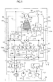
- a hydraulic system embodying the present invention comprises a reservoir tank 56 reserving working fluid and a hydraulic pump 54 sucking in the working fluid from the reservoir tank 56 by way of a fluid suck passageway 63 to increase in pressure and deliver the working fluid.
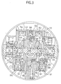
- the hydraulic system is shown in Fig. 2 as comprising a casing 11 fixedly attached to a frame member of a crawler vehicle not shown and including a cylindrical casing 12 and a valve casing 13 tightly connected to each other.
- the cylindrical casing 12 accommodates a cam plate type hydraulic motor 14 for driving the crawler vehicle.
- the cam plate type hydraulic motor 14 comprises an output rotation shaft 17 rotatably supported by the cylindrical casing 12 and the valve casing 13 by way of bearings 15 and 16.
- the output rotation shaft 17 has one end portion protruded from the cylindrical casing 12and securely connected to a sprocket held in mesh with a crawler, neither of the sprocket and crawler being shown.
- the hydraulic motor 14 is shown in Fig. 1 as having first and second inlet/outlet ports 14a and 14b.
- the working fluid is supplied from the hydraulic pump 54 to one of the first and second inlet/outlet ports 14a and 14b through one of first and second fluid supply/discharge passageways 58 and 59 and discharged from the other of the first and second inlet/outlet ports 14a and 14b to the reservoir tank 56 through the other of the first and second fluid supply/discharge passageways 58 and 59.
- the output rotation shaft 17 of the hydraulic motor 14 is rotated in a direction at the time when the working fluid from the hydraulic pump 54 is received by the first inlet/outlet port 14a, rotated in the opposite direction at the time when the working fluid from the hydraulic pump 54 is received by the second inlet/outlet port 14b.
- a reference numeral 20 denotes a cylinder block in which the other end of the rotation shaft 17 is housed and to which the other end of the rotation shaft 17 is connected through a spline connection.
- the cylinder block 20 is formed with a plurality of cylinder through bores 21 arranged in circumferentially equiangularly spaced relationship to each other and axially extending from one end of the cylinder block 20 to the other end portion of the cylinder block 20 in a parallel relation ship to the rotation shaft 17.
- the cylinder block 20 have a plurality of projection plungers 23 slidably received in the cylinder through bores 21, respectively, each of the projection plungers 23 being formed with a globular portion 22 each capable of being protruded from one end portion of the cylinder block 20.
- a reference numeral 24 denotes a timing plate that is fixedly connected to the valve casing 13 and intervenes between the cylinder block 20 and the valve casing 13.
- the timing plate 24 is formed with a pair of arched through bores 25 symmetrically arranged with respect to an axis of the cylinder block 20 and each brought alternatively into fluid communication with and into fluid discommunication with the cylinder through bores 21 in accordance with the rotation of the cylinder block 21 about the output rotation shaft 17 with respect to the timing plate 20.
- the camp plate 28 has a slant surface 29 that is slanted with respect to an imaginary plane intersecting the output rotation shaft 17 of the hydraulic motor 14 at a right angle and as a consequence the cam plate 28 is divided into a thin plate portion 30 and a thick plate portion 31 by an imaginary plane on which the rotation axis of the output rotation shaft 17 of the hydraulic motor 14 extends.
- the cam plate 28 further has a back surface 32 comprising a first flat surface 33 that is parallel to the imaginary plane intersecting the output rotation shaft 17 at a right angle and partially forms a surface of the thin plate portion 30 of the cam plate 28, and a second flat surface 34 that is slanted with respect to the first flat surface 33 at a predetermined little angle and partially forms a surface of the thick plate portion 31 of the cam plate 28.
- the cam plate 28 is adapted to be pivotable with respect to a fulcrum member 35 disposed on a boundary between the first and second flat surfaces 33 and 34 to assume two different cam plate positions consisting of a first cam plate position in which the first flat surface 33 of the cam plate 28 is held in contact with an inner flat surface of the cylindrical casing 12, and a second cam plate position in which the second flat surface 34 of the cam plate 28 is held in contact with the inner flat surface of the cylindrical casing 12.
- the slant surface 29 of the cam plate 28 is slidably engaged with a plurality of shoe members 38 which is equal in number to the projection plungers 23, and each which has a recess and is connected to each of the projection plungers 23 in such a way that the recess of each of the shoe members 38 has the globular portion 22 of each of the projection plungers 23 pivotably received therein.
- the cylindrical casing 12 is formed with a cylinder chamber 40 which is opened at the inner surface of the cylindrical casing 12 facing to the first flat surface 33 of the cam plate 28 and in which a press piston 41 is slidably received.
- the cylindrical casing 12 is further formed with a speed change fluid passageway 42 on which a restrictor 124 is provided and which is held in fluid communication with the cylinder chamber 40.
- the cam plate 28 When, on the other hand, the working fluid of high pressure is interrupted to be supplied to the cylinder chamber 40 by the way of the speed change fluid passageway 42, the cam plate 28 is shifted to assume the second plate position to the first plate position.
- the cam plate 23 thus shiftable to assume the first and second cam plate positions enables the projection plungers 23 contained in the cylinder block 20 to axially move with different strokes, thereby making it possible to change the rotation speed of the output rotation shaft 17 between different speed conditions.
- the speed change fluid passageway 42 is connectable to a control fluid passageway 112 and a fluid drain passageway 101 through a speed control valve 113.
- the speed control valve 113 is shown in Fig.
- control valve spool 120 as comprising a control valve spool 120 slidably received by the valve casing 13, and a helical spring 121 engaged with one end portion of the control valve spool 120 and urging the control valve spool 120 to move axially against pilot pressure of the working fluid which is supplied to a pilot hydraulic chamber 120a and is exerted on the other end portion of the control valve spool 120.
- the speed control valve 113 thus constructed is operative to assume two different control valve positions in accordance with the pilot pressure of the working fluid exerted on the other end portion of the control valve spool 120 Turning back to Fig.
- control valve positions of the speed control valve 113 consist of a first control valve position G in which the speed change fluid passageway 42 is held in fluid communication with the control fluid passageway 112, and a second control valve position I in which the speed change fluid passageway 42 is held in fluid communication with the fluid drain passageway 101.
- the working fluid in the pilot hydraulic chamber 120a of the control spool valve 120 is supplied from a hydraulic pump 114 through a pilot fluid passageways 119 and a fluid feed passageway 116 from a hydraulic pump 114.
- the pilot fluid passageway 119 is connectable not only to the fluid feed passageway 116 but to a fluid drain passageway 123 through a two-position switching valve 117.
- the switching valve 117 is operated to assume two different switching valve positions in accordance with manual operation by the crawler vehicle driver.
- the valve positions of the two-position switching valve 117 consist of a first switching valve position F in which the pilot fluid passageway 119 is held in fluid communication with the fluid feed passageway 116, and a second switching valve position H in which the pilot fluid passageway 119 is held in fluid communication with the fluid drain passageway 123.
- the hydraulic pump 114 sucks the working fluid from the reservoir tank 56 through a fluid suck passageway 115 in order to force the working fluid into the fluid feed passageway 116.
- On the fluid feed passageway 116 is provided a relief valve 122 that prevents pressure of the working fluid in the fluid passageway 116 from exceeding a predetermine pressure level.
- a reference numeral 111 denotes a shuttle valve that has the control fluid passageway 112 brought into fluid communication selectively with a first selection fluid passageway 81 and a second selection fluid passageway 82.
- the first and selection fluid passageways 81 and 82 are respectively held in fluid communication with a hydraulic motor side passageway portion 58a of a first supply/discharge fluid passageway 58 and a hydraulic motor side passageway portion 59a of a second supply/discharge fluid passageway 59 described hereinlater in detail.
- the working fluid in one of the first and second selection fluid passageways 81 and 82 to be brought into fluid communication with the control fluid passageway 112 has a fluid pressure higher than that ofthe other of the first and second selection fluid passageways 81 and 82.
- a reference numeral 45 denotes a plurality of first friction ring plates arranged in axially spaced and coaxial relationship to one another and securely connected to an outer peripheral surface portion of the cylinder block 20 of the hydraulic motor 14, while a reference numeral 46 denotes a plurality of second friction ring plates securely connected to an inner peripheral surface portion of the cylindrical casing 12 and arranged in alternate and coaxial relationship to the first friction ring plates 45.
- the first and second friction ring plates 45 and 46 as a whole form a friction plate assembly.
- the cylindrical casing 12 slidably receives a brake piston 47 which is located between the valve casing 13 and the friction plate assembly and surrounds the cylinder block 20.
- the brake piston 47 defines a main chamber 48 in cooperation with the cylindrical casing 12.
- a plurality of brake springs 49 each urging the brake piston 47 to push the first friction ring plates 45 to the second friction ring plates 46 in turn.
- the brake springs 49 collectively force the brake piston 47 to push the first friction ring plates 45 to the second friction ring plates 46.
- the first and second friction ring plates 45 and 46 are caused by the resilient forces of the brake springs 49 to be engaged with one another and generate a large friction force therebetween, and accordingly the output rotation shaft 17 is mechanically braked by the large friction force transmitted through the cylinder block 20 from the friction plate assembly.
- the brake piston 47 When the working fluid of high pressure is supplied to the main hydraulic chamber 48, the brake piston 47 is forced by the working fluid pressure in the main hydraulic chamber 48 to axially move against the resilient forces of the brake springs 49. At this time, there is no friction force between the first and second friction ring pates 45 and 46 and as a consequence the output rotation shaft 17 as well as the cylinder block 20 is released from the mechanical brake force based on the brake springs 49.
- the above-mentioned first and second friction ring plates 45 and 46, brake piston 47 and brake springs 49 collectively form a mechanical brake assembly 50.
- the hydraulic system further comprises a shuttle valve 98 provided on the first and second fluid supply/discharge passageways 58 and 59 for having the release fluid passageway 99 brought into fluid communication selectively with the first and second fluid supply/discharge passageways 58 and 59.
- the working fluid in one of the first and second fluid supply/discharge passageways 58 and 59 brought into fluid communication with the release fluid passageway 99 is higher in pressure than that in the other of the first and second fluid supply/discharge passageways 58 and 59.
- the hydraulic system further is shown in Fig. 1 as further comprises a control valve 100 which is provided on the release fluid passageway 99 and operative to assume two different control valve positions in accordance with the fluid pressure in the release fluid passageway 99.
- the control valve positions of the control valve 100 consist of a first control valve position D in which the working fluid is permitted to flow the release fluid passageway 99 between the shuttle valve 98 and the main hydraulic chamber 48, and a second control valve position E in which the working fluid is discharged from the main hydraulic chamber 48 to the reservoir tank 56 through the fluid drain passageway 101.
- the hydraulic system further comprises a directional control valve 53 of three-position switching type which is provided on the first and second fluid supply/discharge passageways 58 and 59 and communicates with a hydraulic pump 54 and a reservoir tank 56 through a fluid feed passageway 55 and a fluid drain passageway 57, respectively.
- the directional control valve 53 is operative to assume three different directional control valve positions in accordance with manual operation by the crawler vehicle driver.
- the directional control valve positions consist of a first directional control valve position L in which the working fluid is permitted to be supplied from the hydraulic pump 54 to the first fluid supply/discharge passageway 58 through the fluid feed passageway 55 and to be discharged from the second fluid supply/discharge passageway 59 to the reservoir tank 56 through the fluid drain passageway 55, a second directional control valve position K in which the working fluid is permitted to be discharged from the first and second fluid supply/discharge passageways 58 and 59 to the reservoir tank 56 through the fluid drain passageway 57, and a third directional control valve position J in which the working fluid is permitted to be supplied from the hydraulic pump 54 to the second supply/discharge fluid passageway 59 through the fluid feed passageway 55 and to be discharged from the first supply/discharge fluid passageway 58 through the fluid drain passageway 57.
- On the fluid feed passageway 55 is provided a relief valve 62 that prevents pressure of the working fluid in the fluid feed passageway 55 from exceeding a predetermine pressure level.
- the brake piston 47 and the cylindrical casing 12 further defines a secondary hydraulic chamber 105 held in fluid communication with the release fluid passageway 99 through a fluid feed/return passageway 106.
- a brake resistance restrictor 107 on the fluid feed/return passageway 106 for restricting flow of the working fluid in the fluid feed/return passageway 106.
- the brake piston 47 further has a second piston area portion on which the fluid pressure in the secondary hydraulic chamber 105 is exerted so as to disengage the brake piston 47 from the output rotation shaft 17 of the hydraulic motor 14 against resilient force of the brake springs 49.
- the second piston area portion of the brake piston 47 has an effective area smaller than that of the first piston area portion of the brake piston 47.
- the hydraulic system further comprises a counterbalance valve 65 provided on the first and second fluid supply/discharge passageways 58 and 59 between the hydraulic pump 14 and the directional control valve 53.
- the counterbalance valve 65 is designed to prevent the working fluid from being forced by the hydraulic motor 14 into one of the first and second fluid supply/discharge passageways 58 and 59 when the hydraulic motor 14 is still at work under condition that the directional control valve 53 is shifted to assume the second directional control valve position K.
- the hydraulic system further comprises a first check valve 90 provided on the first fluid supply/discharge passageway 58 and a second check valve 91 provided on the second fluid supply/discharge passageway 59.
- the first fluid supply/discharge passageway 58 is divided by the first check valve 90 into a hydraulic motor side passageway portion 58a and a directional control valve side passageway portion 58b.
- the second fluid supply/discharge passageway 59 is divided by the second check valve 91 into a hydraulic motor side passageway portion 59a and a directional control valve side passageway portion 59b.
- the counterbalance valve 65 comprises first and second valve spools 68 and 69 arranged into alignment with each other, and respectively having inner end portions 68a and 69a facing to each other and outer end portions 68b and 69b remote from each other.
- the first and second valve spools 68 and 69 are slidably received by the valve casing 13.
- the inner end portions 68a and 69a of the first and second valve spools 68 and 69 and the valve casing 13 collectively define a median hydraulic chamber 76 held in fluid communication with the fluid feed/return passageway 106 between the secondary hydraulic chamber 105 and the brake resistance restrictor 107.
- the outer end portion 68b of the first valve spool 68 defines, in cooperation with the valve casing 13, a first side hydraulic chamber 72 held in fluid communication with the directional control valve side passageway portion 58a of the first fluid support/discharge passageway 58.
- the outer end portion 69b of the second valve spool 69 defines, in cooperation with the valve casing 13, a second side hydraulic chamber 73 held in fluid communication with the directional control valve side passageway portion 59b of the second fluid support/discharge passageway 59.
- the first valve spool 68 of the counterbalance valve 65 is formed with a through bore of small diameter serving as a first restrictor 95 which is provided between the first side hydraulic chamber 72 and the directional control valve side passageway portion 58b of the first fluid support/discharge passageway 58 for restricting flow of the working fluid between the first side hydraulic chamber 72 and the directional control valve side passageway portion 58b of the first fluid supply/discharge passageway 58.
- the second spool 69 of the counterbalance valve 65 is formed with a through bore of small diameter serving as a second restrictor 96 which is provided between the second side hydraulic chamber 73 and the directional control valve side passageway portion 59b of the second fluid supply/discharge passageway 59 for restricting flow of the working fluid between the second side hydraulic chamber 73 and the directional control valve side passageway portion 59b of the second supply/discharge fluid passageway 59.
- the counterbalance valve 65 further comprises first and second return springs 74 and 75 received in the first and second side hydraulic chambers 72 and 73 and urging the first and second valve spools 68 and 69 to move inward, respectively.
- the first valve spool 68 of the counterbalance valve 65 is axially movable to assume a first spool position C in which the working fluid is permitted to flow between the hydraulic motor side passageway portion 58a of the first fluid support/discharge passageway 58 and the directional control valve side passageway portion 58b of the first fluid supply/discharge passageway 58, and a second spool position A in which the working fluid is interrupted from flowing between the hydraulic motor side passageway portion 58a of the first fluid supply/discharge passageway 58 and the directional control valve side passageway portion 58b of the first fluid supply/discharge passageway 58.
- the second valve spool 69 of the counterbalance valve 65 is axially movable to assume a first spool position C in which the working fluid is permitted to flow between the hydraulic motor side passageway portion 59a of the second fluid supply/discharge passageway 59 and the directional control valve side passageway portion 59b of the second fluid supply/discharge passageway 59 and a second spool position A in which the working fluid is interrupted from flowing between the hydraulic motor side passageway portion 59a of the second fluid supply/discharge passageway 59 and the directional control valve side passageway portion 59b of the second fluid supply/discharge passageway 59.
- the working fluid is further permitted by the counterbalance valve 65 to flow between the hydraulic motor side passageway portion 58a of the first fluid supply/discharge passageway 58 and the motor side passageway portion 59a of the second fluid supply/discharge passageway 59.
- the working fluid is interrupted from flowing between the hydraulic motor side passageway portion 58a of the first fluid supply/discharge passageway 58 and the hydraulic motor side passageway portion 59a of the second fluid supply/discharge passageway 59.
- the first valve spool 68 of the counterbalance valve 65 further assumes a third spool position B between the first spool position C and the second spool position A of the first valve spool 68.
- the second valve spool 69 of the counterbalance valve 65 further assumes a third spool position B between the first spool position C and the second spool position A of the second valve spool 69.
- the directional control valve 53 is shifted to assume the first directional control valve position L or the third directional control valve position J.
- the directional control valve 53 is shifted to assume the third directional control valve position J, the following description will be made.
- the directional control valve 53 is shifted to assume the third directional control valve position J, the working fluid of high pressure is supplied to the second fluid supply/discharge passageway 59 from the hydraulic pump 54.
- the second fluid supply/discharge passageway 59, the second selection fluid passageway 82, the fluid feed/return passageway 106, the release fluid passageway 99 and the control fluid passageway 112 serve as high pressure fluid passageways.
- the working fluid of high pressure is supplied from the hydraulic pump 54 to about half of the cylinder through bores 21 through the fluid feed passageway 55, the second fluid supply/discharge passageway 59 and the arched through bores 25, and accordingly the globular portions of the projection plungers 23 are protruded in turn from the cylinder block 20 to push the slant surface 29 of the cam plate 28.
- the projection plungers 23 and the shoe members 38 are forced by component of the push force exerted on the projection plungers 23 to move from the thick plate portion 31 of the cam plate 28 toward the thin plate portion 30 of the cam plate 28, thereby rotating the output rotation shaft 17 of the hydraulic motor 14 with the projection plungers 23 and cylinder block 20 to drive the crawler vehicle.
- the working fluid of high pressure in the second fluid supply/discharge passageway 59 is permitted by the shuttle valve 98 to be supplied to the release fluid passageway 99.
- the working fluid of high pressure in the release fluid passageway 99 causes the control valve 100 to assume the first control valve position D and is supplied to the main hydraulic chamber 48 of the mechanical brake assembly 50.
- the working fluid of high pressure in the release fluid passageway 99 is supplied to the secondary hydraulic chamber 105 of the mechanical brake assembly 50 through the fluid feed/return passageway 106.
- the brake piston 47 of the mechanical brake assembly 50 is forced to be disengaged by the fluid pressure both in the main hydraulic chamber 48 and the secondary hydraulic chamber 105 from the first and second friction ring plates 45 and 46 against the resilient force of the brake springs 49 and as a result the output rotation shaft 17 of the hydraulic motor 14 is released from the friction force generated between the first and second friction ring plates 45 and 46, i.e., the mechanical brake force generated by the brake springs 49, thereby permitting the output rotation shaft 17 of the hydraulic motor 14 to rotate freely.
- the working fluid of high pressure is further supplied not only from the fluid feed/return passageway 106 to the median hydraulic chamber 76 of the counterbalance valve 65 but also from the release fluid passageway 99 to the second side hydraulic chamber 73 of the counterbalance valve 65.
- the first side hydraulic chamber 72 of the counterbalance valve 65 is held in fluid communication with the first fluid supply/discharge passageway 58 serving as a drain passageway, so that the first valve spool 68 of the counterbalance valve 65 is moved to assume the first spool valve position C.
- the working fluid in the cylinder through bores 21 is discharged to the reservoir tank 56 through the hydraulic motor side passageway portion 58a of the first fluid supply/discharge passageway 58, the fluid passageway 81 and the directional control valve side passageway portion 58b of the first fluid supply/discharge passageway 58 and the fluid drain passageway 57.
- the two-position switching valve 117 is shifted to assume the first switching valve position F in which the working fluid of high pressure is supplied from the hydraulic pump 114 to the pilot hydraulic chamber 120a of the speed control valve 113 through the pilot fluid passageway 119.
- the speed control valve 113 is operated by the pilot fluid pressure in the pilot hydraulic chamber 120a to assume the first speed control valve position G and accordingly the working fluid of high pressure selected by the shuttle valve 111 is supplied to the cylinder chamber 40 through the control fluid passageway 112 and the speed change fluid passageway 42.
- the working fluid of high pressure in the cylinder chamber 40 causes the press piston 41 to be protruded from the inner surface of the cylindrical casing 12 so that the cam plate 28 is pivoted on the fulcrum member 35 to assume the second position in which the second flat surface 34 of the cam plate 28 is in contact with the inner surface of the cylindrical casing 12.
- the two-position switching valve 117 is shifted to assume the second switching valve position H in which the working fluid is discharged from the pilot hydraulic chamber 120a of the control valve 113 to the reservoir tank 56 through the pilot fluid passageway 119 and the fluid drain passageway 123.
- the speed control valve 113 is operated by the helical spring 121 to assume the second speed control valve position I in which the working fluid in the cylinder chamber 40 is discharged to the reservoir tank 56 through the speed change fluid passageway 42 and the fluid drain passageway 101.
- the cam plate 28 is forced by the projection plungers 23 to be pivoted on the fulcrum member 35 and accordingly assumes the first position in which the first flat surface 33 of the cam plate 28 is in contact with the inner surface of the cylindrical casing 12.
- the directional control valve 53 is changed from the third directional control valve position J to the second directional control valve position K in which the first and second fluid supply/discharge passageways 58 and 59 are brought into fluid communication with each other and serve as low pressure fluid passageways.
- the release fluid passageway 99 serves as a low pressure fluid passageway so that the working fluid of high pressure is stopped from being supplied to the main hydraulic chamber 48 of the mechanical brake 50.
- the control valve 100 is shifted to assume the second valve position E in which the working fluid in the main hydraulic chamber 48 is discharged to the reservoir tank 56 through the fluid drain passageway 101.
- the fluid pressure in the secondary hydraulic chamber 105 is gradually decreased to the extent of a predetermined pressure level larger than the low pressure level of the reservoir tank 56 for the short time between the points T1 and T2 because of the fact that the brake resistance restrictor 107 is provided on the fluid feed/return passageway 106 for restricting the flow of the working fluid in the fluid feed/return passageway 106.
- the fluid pressure in the secondary hydraulic chamber 105 smaller than delivery pressure of the hydraulic pump 54 and gradually decreased is exerted on the second piston area portion of the brake piston 47 of the mechanical brake assembly 50 to prevent the brake piston 47 from being immediately engaged with the first and second friction ring plates 45 and 46.
- the first friction ring plates 45 are engaged with the second friction ring plates 46 by turns at the point T2, thereby applying the mechanical brake force of the mechanical brake 50 to the output rotation shaft 17 of the hydraulic motor 14. Since part of the resilient forces of the brake springs 49 are canceled by the fluid pressure in the secondary hydraulic chamber 105, the mechanical brake force based on the resilient force of the brake springs 49 and the fluid pressure in the secondary hydraulic chamber 105 becomes considerably small in comparison with that based only on the brake springs 49.
- the rotation speed of the rotation shaft 17 of the hydraulic motor 14, i.e., the driving speed of the crawler vehicle is gradually reduced at deceleration represented by 0.4g or less, so that the crawler vehicle can be effectively prevented from incurring the mighty shock at the time when the crawler vehicle is decelerated and stopped.
- the fluid pressure in the secondary hydraulic chamber 105 of the mechanical brake assembly 50 is substantially held at a constant low pressure level during a time between the points T2 and T3 as understood from Fig. 5.
- the reason is described as follows.
- the second valve spool 69 of the counterbalance valve 65 is moving from the second spool position A toward the first spool position C, and consequently the working fluid which is equal in quantity to that discharged through the brake resistance restrictor 107 is continuously supplied from the median hydraulic chamber 76 of the counterbalance valve 65 to the fluid feed/return passageway 106 between the secondary hydraulic chamber 105 and the brake resistance restrictor 107.
- the fluid pressure in the secondary hydraulic chamber 105 as well as in the fluid feed/return fluid passageway 106 between the secondary hydraulic chamber 105 and the brake resistance restrictor 107 is held at a constant low pressure level. Therefore, the mechanical brake force applied by the mechanical brake assembly 50 to the output rotation shaft 17 of the hydraulic motor 14 is held at a constant small force level during a certain time, thereby making it possible to more effectively prevent the crawler vehicle from incurring the mighty shock at the time when the crawler vehicle is decelerated and stopped.
- the first valve spool 68 of the counterbalance valve 65 is, however, returned to the second spool position A from the third spool position B to disconnect the hydraulic motor side passageway portion 58a of the first fluid supply/discharge passageway 58 from the directional control valve side passageway portion 58b of the first fluid supply/discharge passageway 58 at the point T3, and accordingly the working fluid in the hydraulic motor side passageway portion 58a of the first fluid supply/discharge passageway 58 is increased in pressure, thereby applying a fluid brake force to the hydraulic motor 14. Therefore, the output rotation shaft 17 of the hydraulic motor 14 is braked and stopped both by the mechanical brake force generated by the mechanical brake assembly 50 and by the fluid brake force based on the operation of the counterbalance valve 65.
- the brake force applied by the mechanical brake assembly 50 to the hydraulic motor 14 is based on only the mechanical brake force and consequently becomes large in comparison with that based on the mechanical brake force partially canceled by the fluid pressure in the secondary hydraulic chamber 105 because of the fact that the fluid pressure in the secondary hydraulic chamber 105 is reduced to the extent of the low pressure level of the reservoir tank 56.
- the hydraulic motor 14 is completely stopped at a point T4 shown in Fig. 5
- the mechanical brake force based on the static friction force generated between the first and second friction ring plates 45 and 46 is applied to the output rotation shaft 17 of the hydraulic motor 14. If the hydraulic motor 14 is completely stopped before the point T3, there is provided no fluid brake force applied to the hydraulic motor 14.
- the output rotation shaft 17 of the hydraulic motor 14 continues to rotate in the same direction for an extremely short time. At this time, the hydraulic motor 14 tries to suck the working fluid from the second fluid supply/discharge passageway 59 serving as a low pressure passageway and force the working fluid into the first fluid supply/discharge fluid passageway 58 serving as a high pressure passageway.
- the working fluid in the first side hydraulic chamber 72 of the counterbalance valve 65 is increased in pressure to the extent of high pressure level equal to the fluid pressure in the first fluid supply/discharge passageway 58, while the working fluid in the second side hydraulic chamber 73 of the counterbalance valve 65 is reduced in pressure to the extent of the low pressure level of the reservoir tank 56.
- the first valve spool 68 of the counterbalance valve 65 is moved from the first spool position C to the second spool position A, while the second valve spool 69 of the counterbalance valve 65 is moved from the second spool position A to the first spool position C.
- the fluid pressure in the median hydraulic chamber 76 between the first and second valve spools 69 and 69 is held at the high pressure level and there is no working fluid supplied to and discharged from the median hydraulic chamber 76 of the counterbalance valve 65.
- the first and second valve spools 68 and 69 are axially moved at the same speeds in invariably spaced relationship to each other, so that the first and second valve spools 68 and 69 simultaneously assume the third spool positions B in which the first selection fluid passageway 81 is brought into fluid communication with the second selection fluid passageway through the connection fluid passageway 83.
- the working fluid of high pressure is, therefore, discharged from the first fluid supply/discharge passageway 58 to the second fluid supply/discharge passageway 59 containing the working fluid of low pressure therein, thereby preventing surge pressure from arising in the first fluid supply/discharge passageway 58 and preventing cavitation from being caused to the second fluid supply/discharge passageway 59.
- first and second valve spools 68 and 69 of the counterbalance valve 65 are formed by different parts, respectively, the first and second valve spools 68 and 69 may be integrally formed with each other.
- a pair of hydraulic chambers in place of the median hydraulic chamber 76 can be defined, in cooperation with the valve casing, by one end portion and the other end portion, respectively, of one spool body collectively formed by the first and second spools.
- the median hydraulic chamber 76 of the counterbalance valve 65 is held in fluid communication with the fluid feed/return passageway 106 in order to the replenish the fluid feed/return passageway 106 with the working fluid contained in the median hydraulic chamber 76, the median hydraulic chamber 76 can be disconnected to the fluid feed/return passageway 106.
- the fluid pressure in the secondary hydraulic chamber 105 of the mechanical brake assembly 50 is relatively quickly reduced to the extent of the low pressure level of the reservoir tank 56.
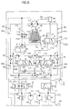
- Fig.6 shows a second preferred embodiment of a hydraulic system according to the present invention.
- the second embodiment herein shown is a modification of the first embodiment shown in Figs.1 to 5 and comprises a hydraulic motor 14, a hydraulic mechanical brake assembly 50, a control valve 100, a speed control valve 113, a shuttle valve 111, a first check valve 90, a second check valve 91, a counterbalance valve 65, a shuttle valve 98, a directional control valve 53, a relief valve 62, a hydraulic pump 54, a two-position switching valve 117, a hydraulic pump 54, a relief valve 122 and a reservoir tank 56 which are entirely similar to their respective counterparts in the first embodiment of Figs.1 to 4.
- the hydraulic system as shown in Fig.6 differs from the first embodiment of Figs.1 to 5 simply in a hydraulic circuit held in fluid communication with the secondary hydraulic chamber 105, and only the difference between the first and second embodiments will be described hereinlater in order to avoid the repeated recitation.
- the secondary hydraulic chamber 105 of the mechanical brake assembly 50 is held in fluid communication with the reservoir tank 56 through a fluid feed/return passageway 156 that is held in fluid communication with the fluid drain passageway 101.
- the brake resistance restrictor 157 for restricting flow of the working fluid in the fluid feed/return passageway 156.
- the fluid drain passageway 101 is held in fluid communication with the fluid feed/return passageway 156 between the brake resistance restrictor 157 and the secondary hydraulic chamber 105 through another fluid feed/return passageway 158 on which a check valve 159 provided for permitting the working fluid to flow only from the reservoir tank to the secondary hydraulic chamber 105 through the fluid drain passageway 101 and the another fluid feed/return passageway 158.
- the hydraulic system shown in Fig. 6 is advantageous in that the crawler vehicle can be effectively prevented from incurring the mighty shock at the time when the crawler vehicle is decelerated and stopped.
- the secondary hydraulic chamber 105 of the mechanical brake assembly 50 is not held in fluid communication with the release fluid passageway 99. Since there is no working fluid supplied to the fluid feed/return passageway 156 between the secondary hydraulic chamber 105 and the brake resistance restrictor 157 during the brake operation of the mechanical brake assembly 50, the hydraulic system shown in Fig. 6 differs from the first embodiment shown in Figs. 1 to 5 in that the fluid pressure in the secondary hydraulic chamber 105 of the mechanical brake assembly 50 is relatively quickly reduced to the extent of the low pressure level of the reservoir tank 56.
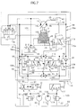
- Figs. 7 and 8 show a third preferred embodiment of a hydraulic system according to the present invention.
- the third embodiment herein shown is a modification of the first embodiment shown in Figs.1 to 5 and comprises a hydraulic motor 14, a hydraulic mechanical brake assembly 50, a control valve 100, a speed control valve 113, a shuttle valve 111, a first check valve 90, a second check valve 91, a counterbalance valve 65, a shuttle valve 98, a directional control valve 53, a relief valve 62, a hydraulic pump 54, a two-position switching valve 117, a hydraulic pump 54, a relief valve 122 and a reservoir tank 56 which are entirely similar to their respective counterparts in the first embodiment of Figs. 1 to 4.
- the hydraulic system as shown in Fig. 7 differs from the first embodiment of Figs. 1 to 5 simply in a hydraulic circuit held in fluid communication with the secondary hydraulic chamber 105, and only the difference between the first and third embodiments will be described hereinlater in order to avoid the repeated
- a selection valve 173 on the first and second fluid supply/discharge passageways 58 and 59.
- the selection valve 173 is operative to assume three different selection valve positions in accordance with the difference in pressure between the working fluid in the first fluid supply/discharge passageway 58 and the working fluid in the second fluid supply/discharge passageway 59
- the selection valve positions consist of a first selection valve position P in which the working fluid is permitted to flow between the first fluid supply/discharge passageway 58 and the secondary hydraulic chamber 105 through a fluid feed/return passageway 176 and interrupted from flowing between the second fluid supply/discharge passageway 59 and the secondary hydraulic chamber 105 through the fluid feed/return passageway 136, a second selection valve position Q in which the working fluid is interrupted from flowing between the first fluid supply/discharge passageway 58 and the secondary hydraulic chamber 105 and between the second fluid supply/discharge passageway 59 and the secondary hydraulic chamber 105 through the fluid feed/return passageway 136, and a third selection valve
- the selection valve 173 is operated to assume the first selection valve position P when the pressure of the working fluid in the first fluid supply/discharge passageway 58 is smaller than that in the second fluid supply/discharge passageway 59.
- the selection valve 173 is operated to assume the second selection valve position Q.
- the selection valve 173 is operated to assume the third selection valve position R.
- a brake resistance restrictor 177 for restricting flow of the working fluid in the fluid feed/return passageway 176.
- the selection valve 173 is shown in Fig. 8 as comprising a cylindrical member 178 formed with a cylinder bore 178, a valve spool 179 slidably received by the cylindrical member 178, and a plug member 180 having an opening of the cylinder bore 178a hermetically sealed therewith.
- the cylindrical member 178 is further formed with a first fluid port 178b having the cylinder bore 178a held in fluid communication with the first fluid supply/discharge passageway 58, a second fluid port 178c having the cylinder bore 178a held in fluid communication with the second fluid supply/discharge passageway 58, a third fluid port 178d having the cylinder bore 178a held in fluid communication with the fluid feed/return passageway 176.
- a first fluid port 178b having the cylinder bore 178a held in fluid communication with the first fluid supply/discharge passageway 58
- a second fluid port 178c having the cylinder bore 178a held in fluid communication with the second fluid supply/discharge passageway 58
- a third fluid port 178d having the cylinder bore 178a held in fluid communication with the fluid feed/return passageway 176.
- the selection valve 173 assumes the first selection valve position P in which the fluid feed/return passageway 176 is held in fluid communication with the first fluid supply/discharge fluid passageway 58 through the third fluid port 178d, cylinder bore 178a and first fluid port 178b of the selection valve 173.
- the selection valve 173 assumes the second selection valve position Q in which the fluid feed/return passageway 176 is held in fluid disconnection with the first and second fluid supply/discharge fluid passageways 58 and 59.
- the selection valve 173 assumes the third selection valve position R in which the fluid feed/return passageway 176 is held in fluid communication with the second fluid supply/discharge passageway 59 through the third fluid port 178d, cylinder bore 178a and second fluid port 178c of the selection valve 173.
- the hydraulic system shown in Figs. 7 and 8 is advantageous in that the crawler vehicle can be effectively prevented from incurring the mighty shock at the time when the crawler vehicle is decelerated and stopped.
Landscapes
- Engineering & Computer Science (AREA)
- General Engineering & Computer Science (AREA)
- Mechanical Engineering (AREA)
- Physics & Mathematics (AREA)
- Fluid Mechanics (AREA)
- Transportation (AREA)
- Fluid-Pressure Circuits (AREA)
- Operation Control Of Excavators (AREA)
- Braking Systems And Boosters (AREA)
Description
- The present invention relates to a hydraulic system, and more particularly to a hydraulic system comprising a hydraulic motor and a mechanical brake assembly for braking the hydraulic motor and adapted, for example, to a driving device of a crawler vehicle.
- A conventional hydraulic system is disclosed, for example, in Japanese patent laid-open publication No. 4-138960 and shown in Fig. 9 as comprising a
hydraulic pump 210, ahydraulic motor 220, amechanical brake assembly 230, adirectional control valve 240, acounterbalance valve 250, a pilothydraulic circuit 260, areservoir tank 271, arelief valve 272,check valves 273 to 277 andrestrictors hydraulic pump 210 sucks in working fluid reserved by thereservoir tank 271 to increase in pressure and deliver the working fluid. Thehydraulic motor 220 is a fixed displacement axial piston motor and has an output rotation shaft (not shown) mechanically connected to driving axle (not shown) of a crawler vehicle. Thehydraulic motor 220 includes a motor casing (not shown) formed with first and second inlet/outlet ports hydraulic pump 210 to one of the first and second inlet/outlet ports discharge passageways outlet ports reservoir tank 271 through the other of the first and second fluid supply/discharge passageways hydraulic pump 210 is received by the first inlet/outlet port 221 of thehydraulic motor 220, the output rotation shaft of thehydraulic motor 220 is rotated in a direction. When the working fluid from thehydraulic pump 210 is received by the second inlet/outlet port 222 of thehydraulic motor 220, the output rotation shaft of thehydraulic motor 220 is rotated in the opposite direction. - The
mechanical brake assembly 230 comprises abrake piston 231 engageable with the output rotation shaft of thehydraulic motor 220 through a pair of friction pads which are respectively fixed to the motor casing of thehydraulic motor 220 and the output rotation shaft of thehydraulic motor 220 Themechanical brake assembly 230 further comprises acylindrical casing 232 for having thebrake piston 231 slidably received therein and abrake spring 233 for resiliently urging thebrake piston 231 to engage with the output rotation shaft of thehydraulic motor 220. Thebrake piston 231 and thecylindrical casing 232 of themechanical brake assembly 230 collectively define ahydraulic chamber 234 to which the working fluid is supplied through arelease fluid passageway 283 and from which the working fluid is discharged through therelease fluid passageway 283. The pressure of the working fluid in thehydraulic chamber 234 is exerted on an effective area of thebrake piston 231 to disengage thebrake piston 23 1 from the output rotation shaft of thehydraulic motor 220 against resilient force of thebrake spring 233. In themechanical brake assembly 230 thus constructed, the output rotation shaft of thehydraulic motor 220 is mechanically braked by the resilient force of thebrake spring 233 through thebrake piston 231 when the working fluid is discharged from thehydraulic chamber 234 through therelease fluid passageway 283. When, reversely, the working fluid is supplied to thehydraulic chamber 234 through therelease fluid passageway 283, the rotation shaft of thehydraulic motor 220 is released from thebrake piston 231 by the pressure of working fluid in thehydraulic chamber 234 and consequently freely rotatable both in the different directions. - The
directional control valve 240 is provided on the first and second fluid supply/discharge passageways control valve position 240a in which the working fluid is permitted to be supplied from thehydraulic pump 210 to the first fluid supply/discharge passageway 281 and to be discharged from the second fluid supply/discharge passageway 282 to thereservoir tank 271, a second directionalcontrol valve position 240b in which the working fluid is permitted to be discharged from the first and second fluid supply/discharge fluid passageways reservoir tank 271, and a third directionalcontrol valve position 240c in which the working fluid is permitted to be supplied from thehydraulic pump 210 to the second fluid supply/discharge passageway 282 and to be discharged from the first fluid supply/discharge passageway 281. - The
counterbalance valve 250 is provided on therelease fluid passageway 283, and the first and second fluid supply/discharge passageways hydraulic pump 210 and thedirectional control valve 240. On the first fluid supply/discharge passageway 281, thecounterbalance valve 250 is arranged in parallel with thecheck valve 273 that is adapted to permit the working fluid to flow only from thedirectional control valve 240 toward thehydraulic motor 220. On the second fluid supply/discharge fluid passageway 282, likewise, thecounterbalance valve 250 is arranged in parallel with thecheck valve 274 that is adapted to permit the working fluid to flow only from thedirectional control valve 240 toward thehydraulic motor 220. Thecounterbalance valve 250 is operative to three different counterbalance valve positions in accordance with difference in pressure between pilothydraulic chambers counterbalance valve positions discharge passageway 281 between thehydraulic motor 220 and thedirectional control valve 240 and in the second fluid supply/discharge passageway 282 between thehydraulic motor 220 and thedirectional control valve 240, and a thirdcounterbalance valve position 250c in which the working fluid is interrupted from flowing in the first fluid supply/discharge passageway 281 between thehydraulic motor 220 and thedirectional control valve 240 and in the second fluid supply/discharge passageway 282 between thehydraulic motor 220 and thedirectional control valve 240. Therelease fluid passageway 283 is brought into fluid communication with the first fluid supply/discharge passageway 281 when thecounterbalance valve 250 is shifted to assume the firstcounterbalance valve position 250a. When thecounterbalance valve 250 is shifted to assume the secondcounterbalance valve position 250b, therelease fluid passageway 283 is brought into fluid communication with the second fluid supply/discharge passageway 281. When thecounterbalance valve 250 is shifted to assume the secondcounterbalance valve position 250c, therelease fluid passageway 283 is brought into fluid communication with afluid drain passageway 284. The pilothydraulic chamber 251 of thecounterbalance valve 250 is held in fluid communication with the first fluid supply/discharge passageway 281 by way of therestrictor 278 and thecheck valve 276 arranged in parallel with each other. In like manner, the pilothydraulic chamber 252 is held in fluid communication with the second fluid supply/discharge passageway 282 by way of therestrictor 279 and thecheck valve 277 arranged in parallel with each other. The pilothydraulic circuit 260 comprises a check valve 261 and arestrictor 262 provided on therelease fluid passageway 283 in parallel relationship to each other. - The conventional hydraulic system thus constructed is operated as described below. If the
directional control valve 240 is operated to assume the first directionalcontrol valve position 240a, thecounterbalance valve 250 is shifted to assume thefirst counterbalance valve 250a and as a consequence the working fluid of high pressure is supplied from thehydraulic pump 210 to the inlet/outlet port of thehydraulic motor 220. At the same time, the working fluid of high pressure is supplied from thehydraulic pump 210 to thehydraulic chamber 234 of themechanical brake 230 by way of therestrictor 262 of the pilothydraulic circuit 260 and accordingly causes thebrake piston 231 to disengage from the output rotation shaft of thehydraulic motor 220 against the resilient force of thebrake spring 233 of themechanical brake assembly 230. As a result, the output rotation shaft of thehydraulic motor 220 is rotated to provide the drive axle of the crawler vehicle with driving force. When thedirectional control valve 240 is operated to assume the second directionalcontrol valve position 240b, the working fluid in the first and second fluid supply/discharge passageways reservoir tank 271 and decreased in pressure. Simultaneously, the working fluid in thehydraulic chamber 234 of themechanical brake assembly 230 is discharged to thereservoir tank 271 through therelease fluid passageway 283 and the first fluid supply/discharge passageway 281, and accordingly the output rotation shaft of thehydraulic motor 220 is braked by and brought into a halt by thebrake spring 233 of themechanical brake assembly 230. If, at this time, the output rotation shaft of thehydraulic motor 220 is rotated at high speed and continues to rotate for a while, thehydraulic motor 220 serves as a hydraulic pump. In this instance, thecounterbalance valve 250 is shifted to assume thethird counterbalance valve 250 due to the pressure of the working fluid in the pilothydraulic chamber 251 held at high level in comparison with that in the pilothydraulic chamber 252 by therestrictor 278 for a while. This result in the fact that the working fluid is interrupted by thecheck valve 273 and thecounterbalance valve 250 from flowing in the first fluid supply/discharge passageway 281 between thehydraulic motor 220 and thecounterbalance valve 250, thereby furnishing thehydraulic motor 220 with hydraulic resistance. Consequently, the output rotation shaft of thehydraulic motor 220 is braked by a mechanical brake force depending upon thebrake spring 233 of themechanical brake assembly 230 and the hydraulic brake force generated by the operation of thecounterbalance valve 250. - The foregoing conventional control apparatus, however, entails a drawback that the crawler vehicle incurs a mighty shock represented by deceleration exceeding, for example, 0.4g at the time when the crawler vehicle is stopped. More specifically, the
mechanical brake assembly 230 is used as a brake system for holding the crawler vehicle in a halt as well as for bringing the crawler vehicle into a halt. This means that thebrake spring 233 of themechanical brake assembly 230 is required to have an extremely powerful resilience. Thebrake spring 233, therefore, has the crawler vehicle decelerated extremely rapidly when the mechanical brake 30 is at work, thereby causing the crawler vehicle to incur the extremely mighty shock. - The present invention contemplates provision of a hydraulic system overcoming a drawback of prior-art hydraulic system of the described general natures.
- According to one aspect of the present invention there is provided a hydraulic system comprising a reservoir tank reserving working fluid, a hydraulic pump sucking in the working fluid from the reservoir tank to increase in pressure and deliver the working fluid, a hydraulic motor having first and second inlet/outlet ports and having an output rotation shaft, the working fluid being supplied from the hydraulic pump to one of the first and second inlet/outlet ports through one of first and second fluid supply/discharge passageways and discharged from the other of the first and second inlet/outlet ports to the reservoir tank through the other of the first and second fluid supply/discharge passageways, the output rotation shaft being rotated in a direction when the working fluid from the hydraulic pump is received by the first inlet/outlet port, and the output rotation shaft being rotated in the opposite direction when the working fluid from the hydraulic pump is received by the second inlet/outlet port, a mechanical brake assembly having a brake piston engageable with the output rotation shaft of the hydraulic motor, a cylindrical-casing having the brake piston slidably received therein and a brake spring resiliently urging the brake piston to engage with the output rotation shaft of the hydraulic motor, the brake piston and the cylindrical casing collectively defining a main hydraulic chamber to which the working fluid is supplied through a release fluid passageway and from which the working fluid is discharged through the release fluid passageway, the brake piston having a first piston area portion on which pressure of the working fluid in the main hydraulic chamber is exerted so as to disengage the brake piston from the output rotation shaft of the hydraulic motor against resilient force of the brake spring, the output rotation shaft of the hydraulic motor being mechanically braked by the resilient force of the brake spring through the brake piston when the working fluid is discharged from the main hydraulic chamber of the mechanical brake assembly, and the output rotation shaft of the hydraulic motor being released from the brake piston by fluid pressure of the working fluid in the main hydraulic chamber when the working fluid is supplied to the main hydraulic chamber of the mechanical brake assembly; a shuttle valve provided on the first and second fluid supply/discharge passageways for having the release fluid passageway held in fluid communication selectively with the first and second fluid supply/discharge passageways, the working fluid in one of the first and second fluid supply/discharge passageways held in fluid communication with the release fluid passageway being higher in pressure than that in the other of the first and second fluid supply/discharge passageways, a directional control valve provided on the first and second fluid supply/discharge passageways, and operative to assume three different directional control valve positions consisting of a first directional control valve position in which the working fluid is permitted to be supplied from the hydraulic pump to the first fluid supply/discharge passageway and to be discharged from the second fluid supply/discharge passageway to the reservoir tank, a second directional control valve position in which the working fluid is permitted to be discharged from the first and second fluid supply/discharge passageways to the reservoir tank, and a third directional control valve position in which the working fluid is permitted to be supplied from the hydraulic pump to the second fluid supply/discharge passageway and to be discharged from the first fluid supply/discharge passageway, and a counterbalance valve provided on the first and second fluid supply/discharge passageways between the hydraulic pump and the directional control valve, the counterbalance valve being operative to prevent the working fluid from being forced by the hydraulic motor into one of the first and second fluid supply/discharge passageways when the hydraulic motor is still at work under condition that the directional control valve is shifted to assume the second directional control valve position, the brake piston and the cylindrical casing further defining a secondary hydraulic chamber held in fluid communication with the release fluid passageway through a fluid feed/return passageway, the brake piston having a second piston area portion on which pressure of the working fluid in the secondary hydraulic chamber is exerted so as to resist the resilient force of the brake spring, and the hydraulic system further comprising a brake resistance restrictor provided on the fluid feed/return passageway for restricting flow of the working fluid in the fluid feed/return passageway.
- According to another aspect of the present invention there is provided a hydraulic system comprising a reservoir tank reserving working fluid, a hydraulic pump sucking in the working fluid from said reservoir tank to increase in pressure and deliver the working fluid, a hydraulic motor having first and second inlet/outlet ports and having an output rotation shaft, the working fluid being supplied from said hydraulic pump to one of said first and second inlet/outlet ports through one of first and second fluid supply/discharge passageways and discharged from the other of said first and second inlet/outlet ports to said reservoir tank through the other of said first and second fluid supply/discharge passageways, said output rotation shaft being rotated in a direction when the working fluid from said hydraulic pump is received by said first inlet/outlet port, and said output rotation shaft being rotated in the opposite direction when the working fluid from said hydraulic pump is received by said second inlet/outlet port, a mechanical brake assembly having a brake piston engageable with said output rotation shaft of said hydraulic motor, a cylindrical casing having said brake piston slidably received therein and a brake spring resiliently urging said brake piston to engage with said output rotation shaft of said hydraulic motor, said brake piston and said cylindrical casing collectively defining a main hydraulic chamber to which the working fluid is supplied through a release fluid passageway and from which the working fluid is discharged through said release fluid passageway, said brake piston having a first piston area portion on which pressure of the working fluid in said main hydraulic chamber is exerted so as to disengage said brake piston from said output rotation shaft of said hydraulic motor against resilient force of said brake spring, said output rotation shaft of said hydraulic motor being mechanically braked by the resilient force of said brake spring through said brake piston when the working fluid is discharged from said main hydraulic chamber of said mechanical brake assembly, and said output rotation shaft of said hydraulic motor being released from said brake piston by fluid pressure of the working fluid in said main hydraulic chamber when the working fluid is supplied to said main hydraulic chamber of said mechanical brake assembly, a shuttle valve provided on said first and second fluid supply/discharge passageways for having said release fluid passageway held in fluid communication selectively with said first and second fluid supply/discharge passageways, the working fluid in one of said first and second fluid supply/discharge passageways held in fluid communication with said release fluid passageway being higher in pressure than that in the other of said first and second fluid supply/discharge passageways, a directional control valve provided on said first and second fluid supply/discharge passageways, and operative to assume three different directional control valve positions consisting of a first directional control valve position in which the working fluid is permitted to be supplied from said hydraulic pump to said first fluid supply/discharge passageway and to be discharged from said second fluid supply/discharge passageway to said reservoir tank, a second directional control position in which the working fluid is permitted to be discharged from said first and second fluid supply/discharge passageways to said reservoir tank, and a third directional control valve position in which the working fluid is permitted to be supplied from said hydraulic pump to said second fluid supply/discharge passageway and to be discharged from said first fluid supply/discharge passageway, and a counterbalance valve provided on said first and second fluid supply/discharge passageways between said hydraulic motor and said directional control valve, said counterbalance valve being operative to prevent the working fluid from being forced by said hydraulic motor into one of said first and second fluid supply/discharge passageways when said hydraulic motor is still at work under condition that said directional control valve is shifted to assume said second directional control valve position, said brake piston and said cylindrical casing further defining a secondary hydraulic chamber held in fluid communication with said reservoir tank through a fluid feed/return passageway, said brake piston having a second piston area portion on which pressure of the working fluid in said secondary hydraulic chamber is exerted so as to resist the resilient force of said brake spring, and said hydraulic system further comprising a brake resistance restrictor provided on said fluid feed/return passageway for restricting flow of the working fluid in said fluid feed/return passageway.
- According to a further aspect of the present invention there is provided a hydraulic system comprising a reservoir tank reserving working fluid, a hydraulic pump sucking in the working fluid from the reservoir tank to increase in pressure and deliver the working fluid, a hydraulic motor having first and second inlet/outlet ports and having an output rotation shaft, the working fluid being supplied from the hydraulic pump to one of the first and second inlet/outlet ports through one of first and second fluid supply/discharge passageways and discharged from the other of the first and second inlet/outlet ports to the reservoir tank through the other of the first and second fluid supply/discharge passageways, the output rotation shaft being rotated in a direction when the working fluid from the hydraulic pump is received by the first inlet/outlet port, and the output rotation shaft being rotated in the opposite direction when the working fluid from the hydraulic pump is received by the second inlet/outlet port, a mechanical brake assembly having a brake piston engageable with the output rotation shaft of the hydraulic motor, a cylindrical casing having the brake piston slidably received therein and a brake spring resiliently urging the brake piston to engage with the output rotation shaft of the hydraulic motor, the brake piston and the cylindrical casing collectively defining a main hydraulic chamber to which the working fluid is supplied through a release fluid passageway and from which the working fluid is discharged through the release fluid passageway, the brake piston having a first piston area portion on which pressure of the working fluid in the main hydraulic chamber is exerted so as to disengage the brake piston from the output rotation shaft of the hydraulic motor against resilient force of the brake spring, the output rotation shaft of the hydraulic motor being mechanically braked by the resilient force of the brake spring through the brake piston when the working fluid is discharged from the main hydraulic chamber of the mechanical brake assembly, and the output rotation shaft of the hydraulic motor being released from the brake piston by fluid pressure of the working fluid in the main hydraulic chamber when the working fluid is supplied to the main hydraulic chamber of the mechanical brake assembly, a shuttle vaive provided on the first and second fluid supply/discharge passageways for having the release fluid passageway held in fluid communication selectively with the first and second fluid supply/discharge passageways, the working fluid in one of the first and second fluid supply/discharge passageways held in fluid communication with the release fluid passageway being higher in pressure than that in the other of the first and second fluid supply/discharge passageways, a directional control valve provided on the first and second fluid supply/discharge passageways, and operative to assume three different directional control valve positions consisting of a first directional control valve position in which the working fluid is permitted to be supplied from the hydraulic pump to the first fluid supply/discharge passageway and to be discharged from the second fluid supply/discharge passageway to the reservoir tank, a second directional control valve position in which the working fluid is permitted to be discharged from the first and second fluid supply/discharge passageways to the reservoir tank, and a third directional control valve position in which the working fluid is permitted to be supplied from the hydraulic pump to the second fluid supply/discharge passageway and to be discharged from the first fluid supply/discharge passageway; and a counterbalance valve provided on the first and second fluid supply/discharge passageways between the hydraulic motor and the directional control valve, the counterbalance valve being operative to prevent the working fluid from being forced by the hydraulic motor into one of the first and second fluid supply/discharge passageways when the hydraulic motor is still at work under condition that the directional control valve is shifted to assume the second directional control valve position, the brake piston and the casing further defining a secondary hydraulic chamber, the brake piston having a second piston area portion on which pressure of the working fluid in the secondary hydraulic chamber is exerted so as to resist the resilient force of the brake spring, the hydraulic system further comprising a selection valve provided on the first and second fluid supply/discharge passageways and operative to assume three different valve positions consisting of a first selection valve position in which the working fluid is permitted to flow between the first fluid supply/discharge passageway and the secondary hydraulic chamber through a fluid feed/return passageway and interrupted from flowing between the second fluid supply/discharge passageway and the secondary hydraulic chamber through the fluid feed/return passageway, a second selection valve position in which the working fluid is interrupted from flowing between the first fluid supply/discharge passageway and the secondary hydraulic chamber and between the second fluid supply/discharge passageway and the secondary hydraulic chamber through the fluid feed/return passageway, and a third selection valve position in which the working fluid is permitted to flow between the second fluid supply/discharge passageway and the secondary hydraulic chamber through the fluid feed/return passageway and interrupted from flowing between the first fluid supply/discharge passageway and the secondary hydraulic chamber through the fluid feed/return passageway, the selection valve being operated to assume the first selection valve position when the pressure of the working fluid in the first fluid supply/discharge passageway is smaller than that in the second fluid supply/discharge passageway, the selection valve being operated to assume the second selection valve position when the pressure of the working fluid in the first fluid supply/discharge passageway is equal to that in the second fluid supply/discharge passageway, the selection valve being operated to assume the third selection valve position when the pressure of the working fluid in the first fluid supply/discharge passageway is larger than that in the second fluid supply/discharge passageway, and the hydraulic system further comprising a brake resistance restrictor provided on the fluid feed/return passageway for restricting flow of the working fluid in the fluid feed/return passageway.
- The features and advantages of a hydraulic system in accordance with the present invention will be more clearly understood from the following description taken in conjunction with the accompanying drawings in which:
- Fig. 1 is a schematic view showing a first preferred embodiment of the hydraulic system according to the present invention;
- Fig. 2 is a sectional view showing a hydraulic apparatus partly adopting the hydraulic system shown in Fig. 1;
- Fig. 3 is a sectional view showing a counterbalance valve shown in Fig. 1;
- Fig. 4 is an enlarged sectional view partially showing a hydraulic motor and a mechanical brake assembly shown in Fig. 1;
- Fig. 5 is a diagram showing variations of fluid pressure in a main hydraulic chamber of a secondary hydraulic chamber of the mechanical brake assembly, a variation of fluid pressure in a lower fluid supply/discharge passageway shown in Fig. 1, and a variation of total brake force applied to an output rotation shaft of the hydraulic motor;
- Fig. 6 is a schematic view similar to Fig. 1 but shows a second preferred embodiment of the hydraulic system according to the present invention;
- Fig. 7 is a schematic view similar to Fig. 1 but shows a third preferred embodiment of the hydraulic system according to the present invention;
- Fig. 8 is a sectional view showing a selection valve shown in Fig. 7; and
- Fig. 9 is a schematic view showing a conventional hydraulic system.
-
- Referring now to Figs. 1 to 5 of the accompanying drawings, a first preferred embodiment of the present invention will be described hereinafter in detail.
- In Fig. 1, a hydraulic system embodying the present invention comprises a
reservoir tank 56 reserving working fluid and ahydraulic pump 54 sucking in the working fluid from thereservoir tank 56 by way of afluid suck passageway 63 to increase in pressure and deliver the working fluid. The hydraulic system is shown in Fig. 2 as comprising acasing 11 fixedly attached to a frame member of a crawler vehicle not shown and including acylindrical casing 12 and avalve casing 13 tightly connected to each other. Thecylindrical casing 12 accommodates a cam plate typehydraulic motor 14 for driving the crawler vehicle. The cam plate typehydraulic motor 14 comprises anoutput rotation shaft 17 rotatably supported by thecylindrical casing 12 and thevalve casing 13 by way ofbearings output rotation shaft 17 has one end portion protruded from the cylindrical casing 12and securely connected to a sprocket held in mesh with a crawler, neither of the sprocket and crawler being shown. - The
hydraulic motor 14 is shown in Fig. 1 as having first and second inlet/outlet ports hydraulic pump 54 to one of the first and second inlet/outlet ports discharge passageways outlet ports reservoir tank 56 through the other of the first and second fluid supply/discharge passageways output rotation shaft 17 of thehydraulic motor 14 is rotated in a direction at the time when the working fluid from thehydraulic pump 54 is received by the first inlet/outlet port 14a, rotated in the opposite direction at the time when the working fluid from thehydraulic pump 54 is received by the second inlet/outlet port 14b. - Turning back to Fig. 2, a
reference numeral 20 denotes a cylinder block in which the other end of therotation shaft 17 is housed and to which the other end of therotation shaft 17 is connected through a spline connection. Thecylinder block 20 is formed with a plurality of cylinder throughbores 21 arranged in circumferentially equiangularly spaced relationship to each other and axially extending from one end of thecylinder block 20 to the other end portion of thecylinder block 20 in a parallel relation ship to therotation shaft 17. Thecylinder block 20 have a plurality ofprojection plungers 23 slidably received in the cylinder throughbores 21, respectively, each of theprojection plungers 23 being formed with a globular portion 22 each capable of being protruded from one end portion of thecylinder block 20. - A
reference numeral 24 denotes a timing plate that is fixedly connected to thevalve casing 13 and intervenes between thecylinder block 20 and thevalve casing 13. Thetiming plate 24 is formed with a pair of arched throughbores 25 symmetrically arranged with respect to an axis of thecylinder block 20 and each brought alternatively into fluid communication with and into fluid discommunication with the cylinder throughbores 21 in accordance with the rotation of thecylinder block 21 about theoutput rotation shaft 17 with respect to thetiming plate 20. - Between the other end portion of the
cylinder block 20 and thecylindrical casing 12, is disposed a ring-shapedcam plate 28 through which theoutput rotation shaft 17 penetrates. Thecamp plate 28 has aslant surface 29 that is slanted with respect to an imaginary plane intersecting theoutput rotation shaft 17 of thehydraulic motor 14 at a right angle and as a consequence thecam plate 28 is divided into a thin plate portion 30 and athick plate portion 31 by an imaginary plane on which the rotation axis of theoutput rotation shaft 17 of thehydraulic motor 14 extends. Thecam plate 28 further has aback surface 32 comprising a firstflat surface 33 that is parallel to the imaginary plane intersecting theoutput rotation shaft 17 at a right angle and partially forms a surface of the thin plate portion 30 of thecam plate 28, and a secondflat surface 34 that is slanted with respect to the firstflat surface 33 at a predetermined little angle and partially forms a surface of thethick plate portion 31 of thecam plate 28. Thecam plate 28 is adapted to be pivotable with respect to a fulcrum member 35 disposed on a boundary between the first and secondflat surfaces flat surface 33 of thecam plate 28 is held in contact with an inner flat surface of thecylindrical casing 12, and a second cam plate position in which the secondflat surface 34 of thecam plate 28 is held in contact with the inner flat surface of thecylindrical casing 12. Theslant surface 29 of thecam plate 28 is slidably engaged with a plurality ofshoe members 38 which is equal in number to theprojection plungers 23, and each which has a recess and is connected to each of theprojection plungers 23 in such a way that the recess of each of theshoe members 38 has the globular portion 22 of each of theprojection plungers 23 pivotably received therein. - The
cylindrical casing 12 is formed with acylinder chamber 40 which is opened at the inner surface of thecylindrical casing 12 facing to the firstflat surface 33 of thecam plate 28 and in which apress piston 41 is slidably received. Thecylindrical casing 12 is further formed with a speedchange fluid passageway 42 on which arestrictor 124 is provided and which is held in fluid communication with thecylinder chamber 40. When the working fluid of high pressure is supplied to thecylinder chamber 40 by way of the speedchange fluid passageway 42, thepress piston 41 is caused by the working fluid of high pressure to protrude from the inner surface of thecylindrical casing 12 and accordingly causes thecam plate 28 to be shifted from the first cam plate position to the second cam plate position. When, on the other hand, the working fluid of high pressure is interrupted to be supplied to thecylinder chamber 40 by the way of the speedchange fluid passageway 42, thecam plate 28 is shifted to assume the second plate position to the first plate position. Thecam plate 23 thus shiftable to assume the first and second cam plate positions enables theprojection plungers 23 contained in thecylinder block 20 to axially move with different strokes, thereby making it possible to change the rotation speed of theoutput rotation shaft 17 between different speed conditions. The speedchange fluid passageway 42 is connectable to acontrol fluid passageway 112 and afluid drain passageway 101 through aspeed control valve 113. Thespeed control valve 113 is shown in Fig. 2 as comprising acontrol valve spool 120 slidably received by thevalve casing 13, and ahelical spring 121 engaged with one end portion of thecontrol valve spool 120 and urging thecontrol valve spool 120 to move axially against pilot pressure of the working fluid which is supplied to a pilothydraulic chamber 120a and is exerted on the other end portion of thecontrol valve spool 120. Thespeed control valve 113 thus constructed is operative to assume two different control valve positions in accordance with the pilot pressure of the working fluid exerted on the other end portion of thecontrol valve spool 120 Turning back to Fig. 1, the control valve positions of thespeed control valve 113 consist of a first control valve position G in which the speedchange fluid passageway 42 is held in fluid communication with thecontrol fluid passageway 112, and a second control valve position I in which the speedchange fluid passageway 42 is held in fluid communication with thefluid drain passageway 101. - The working fluid in the pilot
hydraulic chamber 120a of thecontrol spool valve 120 is supplied from ahydraulic pump 114 through apilot fluid passageways 119 and afluid feed passageway 116 from ahydraulic pump 114. Thepilot fluid passageway 119 is connectable not only to thefluid feed passageway 116 but to afluid drain passageway 123 through a two-position switching valve 117. The switchingvalve 117 is operated to assume two different switching valve positions in accordance with manual operation by the crawler vehicle driver. The valve positions of the two-position switching valve 117 consist of a first switching valve position F in which thepilot fluid passageway 119 is held in fluid communication with thefluid feed passageway 116, and a second switching valve position H in which thepilot fluid passageway 119 is held in fluid communication with thefluid drain passageway 123. Thehydraulic pump 114 sucks the working fluid from thereservoir tank 56 through afluid suck passageway 115 in order to force the working fluid into thefluid feed passageway 116. On thefluid feed passageway 116, is provided arelief valve 122 that prevents pressure of the working fluid in thefluid passageway 116 from exceeding a predetermine pressure level. - A
reference numeral 111 denotes a shuttle valve that has thecontrol fluid passageway 112 brought into fluid communication selectively with a firstselection fluid passageway 81 and a secondselection fluid passageway 82. The first andselection fluid passageways side passageway portion 58a of a first supply/discharge fluid passageway 58 and a hydraulic motorside passageway portion 59a of a second supply/discharge fluid passageway 59 described hereinlater in detail. The working fluid in one of the first and secondselection fluid passageways control fluid passageway 112 has a fluid pressure higher than that ofthe other of the first and secondselection fluid passageways - In Fig. 4, a
reference numeral 45 denotes a plurality of first friction ring plates arranged in axially spaced and coaxial relationship to one another and securely connected to an outer peripheral surface portion of thecylinder block 20 of thehydraulic motor 14, while areference numeral 46 denotes a plurality of second friction ring plates securely connected to an inner peripheral surface portion of thecylindrical casing 12 and arranged in alternate and coaxial relationship to the firstfriction ring plates 45. The first and secondfriction ring plates cylindrical casing 12 slidably receives abrake piston 47 which is located between thevalve casing 13 and the friction plate assembly and surrounds thecylinder block 20. Thebrake piston 47 defines amain chamber 48 in cooperation with thecylindrical casing 12. Between thebrake piston 47 and thevalve casing 13, is placed a plurality of brake springs 49 each urging thebrake piston 47 to push the firstfriction ring plates 45 to the secondfriction ring plates 46 in turn. When no working fluid of high pressure is supplied to the mainhydraulic chamber 48, the brake springs 49 collectively force thebrake piston 47 to push the firstfriction ring plates 45 to the secondfriction ring plates 46. This results in the fact that the first and secondfriction ring plates output rotation shaft 17 is mechanically braked by the large friction force transmitted through thecylinder block 20 from the friction plate assembly. When the working fluid of high pressure is supplied to the mainhydraulic chamber 48, thebrake piston 47 is forced by the working fluid pressure in the mainhydraulic chamber 48 to axially move against the resilient forces of the brake springs 49. At this time, there is no friction force between the first and secondfriction ring pates output rotation shaft 17 as well as thecylinder block 20 is released from the mechanical brake force based on the brake springs 49. The above-mentioned first and secondfriction ring plates brake piston 47 and brake springs 49 collectively form amechanical brake assembly 50. - The hydraulic system further comprises a
shuttle valve 98 provided on the first and second fluid supply/discharge passageways release fluid passageway 99 brought into fluid communication selectively with the first and second fluid supply/discharge passageways discharge passageways release fluid passageway 99 is higher in pressure than that in the other of the first and second fluid supply/discharge passageways - The hydraulic system further is shown in Fig. 1 as further comprises a
control valve 100 which is provided on therelease fluid passageway 99 and operative to assume two different control valve positions in accordance with the fluid pressure in therelease fluid passageway 99. The control valve positions of thecontrol valve 100 consist of a first control valve position D in which the working fluid is permitted to flow therelease fluid passageway 99 between theshuttle valve 98 and the mainhydraulic chamber 48, and a second control valve position E in which the working fluid is discharged from the mainhydraulic chamber 48 to thereservoir tank 56 through thefluid drain passageway 101. - The hydraulic system further comprises a
directional control valve 53 of three-position switching type which is provided on the first and second fluid supply/discharge passageways hydraulic pump 54 and areservoir tank 56 through afluid feed passageway 55 and afluid drain passageway 57, respectively. Thedirectional control valve 53 is operative to assume three different directional control valve positions in accordance with manual operation by the crawler vehicle driver. The directional control valve positions consist of a first directional control valve position L in which the working fluid is permitted to be supplied from thehydraulic pump 54 to the first fluid supply/discharge passageway 58 through thefluid feed passageway 55 and to be discharged from the second fluid supply/discharge passageway 59 to thereservoir tank 56 through thefluid drain passageway 55, a second directional control valve position K in which the working fluid is permitted to be discharged from the first and second fluid supply/discharge passageways reservoir tank 56 through thefluid drain passageway 57, and a third directional control valve position J in which the working fluid is permitted to be supplied from thehydraulic pump 54 to the second supply/discharge fluid passageway 59 through thefluid feed passageway 55 and to be discharged from the first supply/discharge fluid passageway 58 through thefluid drain passageway 57. On thefluid feed passageway 55, is provided arelief valve 62 that prevents pressure of the working fluid in thefluid feed passageway 55 from exceeding a predetermine pressure level. - The
brake piston 47 and thecylindrical casing 12 further defines a secondaryhydraulic chamber 105 held in fluid communication with therelease fluid passageway 99 through a fluid feed/return passageway 106. There is provided abrake resistance restrictor 107 on the fluid feed/return passageway 106 for restricting flow of the working fluid in the fluid feed/return passageway 106. Thebrake piston 47 further has a second piston area portion on which the fluid pressure in the secondaryhydraulic chamber 105 is exerted so as to disengage thebrake piston 47 from theoutput rotation shaft 17 of thehydraulic motor 14 against resilient force of the brake springs 49. The second piston area portion of thebrake piston 47 has an effective area smaller than that of the first piston area portion of thebrake piston 47. - In Figs. 1 and 3, the hydraulic system further comprises a
counterbalance valve 65 provided on the first and second fluid supply/discharge passageways hydraulic pump 14 and thedirectional control valve 53. Thecounterbalance valve 65 is designed to prevent the working fluid from being forced by thehydraulic motor 14 into one of the first and second fluid supply/discharge passageways hydraulic motor 14 is still at work under condition that thedirectional control valve 53 is shifted to assume the second directional control valve position K. More specifically, the hydraulic system further comprises afirst check valve 90 provided on the first fluid supply/discharge passageway 58 and asecond check valve 91 provided on the second fluid supply/discharge passageway 59. The first fluid supply/discharge passageway 58 is divided by thefirst check valve 90 into a hydraulic motorside passageway portion 58a and a directional control valveside passageway portion 58b. In a similar manner, the second fluid supply/discharge passageway 59 is divided by thesecond check valve 91 into a hydraulic motorside passageway portion 59a and a directional control valveside passageway portion 59b. As will be best shown in Fig. 3, thecounterbalance valve 65 comprises first and second valve spools 68 and 69 arranged into alignment with each other, and respectively havinginner end portions outer end portions valve casing 13. Theinner end portions valve casing 13 collectively define a medianhydraulic chamber 76 held in fluid communication with the fluid feed/return passageway 106 between the secondaryhydraulic chamber 105 and thebrake resistance restrictor 107. Theouter end portion 68b of thefirst valve spool 68 defines, in cooperation with thevalve casing 13, a first sidehydraulic chamber 72 held in fluid communication with the directional control valveside passageway portion 58a of the first fluid support/discharge passageway 58. Similarly, theouter end portion 69b of thesecond valve spool 69 defines, in cooperation with thevalve casing 13, a second sidehydraulic chamber 73 held in fluid communication with the directional control valveside passageway portion 59b of the second fluid support/discharge passageway 59. - The
first valve spool 68 of thecounterbalance valve 65 is formed with a through bore of small diameter serving as afirst restrictor 95 which is provided between the first sidehydraulic chamber 72 and the directional control valveside passageway portion 58b of the first fluid support/discharge passageway 58 for restricting flow of the working fluid between the first sidehydraulic chamber 72 and the directional control valveside passageway portion 58b of the first fluid supply/discharge passageway 58. - The
second spool 69 of thecounterbalance valve 65 is formed with a through bore of small diameter serving as asecond restrictor 96 which is provided between the second sidehydraulic chamber 73 and the directional control valveside passageway portion 59b of the second fluid supply/discharge passageway 59 for restricting flow of the working fluid between the second sidehydraulic chamber 73 and the directional control valveside passageway portion 59b of the second supply/discharge fluid passageway 59. Thecounterbalance valve 65 further comprises first and second return springs 74 and 75 received in the first and second sidehydraulic chambers - The
first valve spool 68 of thecounterbalance valve 65 is axially movable to assume a first spool position C in which the working fluid is permitted to flow between the hydraulic motorside passageway portion 58a of the first fluid support/discharge passageway 58 and the directional control valveside passageway portion 58b of the first fluid supply/discharge passageway 58, and a second spool position A in which the working fluid is interrupted from flowing between the hydraulic motorside passageway portion 58a of the first fluid supply/discharge passageway 58 and the directional control valveside passageway portion 58b of the first fluid supply/discharge passageway 58. - The
second valve spool 69 of thecounterbalance valve 65 is axially movable to assume a first spool position C in which the working fluid is permitted to flow between the hydraulic motorside passageway portion 59a of the second fluid supply/discharge passageway 59 and the directional control valveside passageway portion 59b of the second fluid supply/discharge passageway 59 and a second spool position A in which the working fluid is interrupted from flowing between the hydraulic motorside passageway portion 59a of the second fluid supply/discharge passageway 59 and the directional control valveside passageway portion 59b of the second fluid supply/discharge passageway 59. - When the first and second valve spools 68 and 69 is moved to assume the first spool positions C, respectively, the working fluid is further permitted by the
counterbalance valve 65 to flow between the hydraulic motorside passageway portion 58a of the first fluid supply/discharge passageway 58 and the motorside passageway portion 59a of the second fluid supply/discharge passageway 59. When the first and second valve spools 68 and 69 are moved to assume the second spool positions A, respectively, the working fluid is interrupted from flowing between the hydraulic motorside passageway portion 58a of the first fluid supply/discharge passageway 58 and the hydraulic motorside passageway portion 59a of the second fluid supply/discharge passageway 59. - When hydraulic force based on the pressure of the working fluid exerted on the inner end portion 68a of the first valve spool 68 is larger than the sum of hydraulic force based on the pressure of the working fluid exerted on the outer end portion 68b of the first valve spool 68 and resilient force of the first return spring 74, the first valve spool 68 of the counterbalance valve 65 is moved to assume the first spool position C. When the hydraulic force based on the pressure of the working fluid exerted on the inner end portion 68a of the first valve spool 68 is smaller than the sum of the hydraulic force of the working fluid exerted on the outer end portion 68b of the first spool 68 and the resilient force of the first return spring 74, the first valve spool 68 of the counterbalance valve 65 is moved to assume the second spool position A. When, on the other hand, hydraulic force based on the pressure of the working fluid exerted on the inner end portion 69a of the second valve spool 69 is larger than the sum of hydraulic force of the pressure based on the working fluid exerted on the outer end portion 69b of the second valve spool 69 and resilient force of the second return spring 75, the second valve spool 69 of the counterbalance valve 65 is moved to assume the first spool position C. When the hydraulic force based on the pressure of the working fluid exerted on the inner end portion of the second spool 69 is smaller than the sum of the hydraulic force based on the pressure of the working fluid exerted on the outer end portion 69b of the second valve spool 69 and the resilient force of the second return spring 75, the second valve spool 69 of the counterbalance valve 65 is moved to assume the second spool position A.
- As will be understood from Fig. 1, the
first valve spool 68 of thecounterbalance valve 65 further assumes a third spool position B between the first spool position C and the second spool position A of thefirst valve spool 68. Likewise, thesecond valve spool 69 of thecounterbalance valve 65 further assumes a third spool position B between the first spool position C and the second spool position A of thesecond valve spool 69. When the first and second valve spools 68 and 69 are moved to assume the third spool positions B, respectively, the working fluid is permitted to flow between the hydraulic motorside passageway portion 58a of the first fluid supply/discharge passageway 58 and the hydraulic motorside passageway portion 58a of the second fluid supply/discharge passageway 59. - The operation of the hydraulic system thus constructed will be described hereinafter. In order that the crawler vehicle is driven by the
hydraulic motor 14, thedirectional control valve 53 is shifted to assume the first directional control valve position L or the third directional control valve position J. On the assumption that, in this instance, thedirectional control valve 53 is shifted to assume the third directional control valve position J, the following description will be made. When thedirectional control valve 53 is shifted to assume the third directional control valve position J, the working fluid of high pressure is supplied to the second fluid supply/discharge passageway 59 from thehydraulic pump 54. As a consequence, the second fluid supply/discharge passageway 59, the secondselection fluid passageway 82, the fluid feed/return passageway 106, therelease fluid passageway 99 and thecontrol fluid passageway 112 serve as high pressure fluid passageways. The working fluid of high pressure is supplied from thehydraulic pump 54 to about half of the cylinder throughbores 21 through thefluid feed passageway 55, the second fluid supply/discharge passageway 59 and the arched throughbores 25, and accordingly the globular portions of theprojection plungers 23 are protruded in turn from thecylinder block 20 to push theslant surface 29 of thecam plate 28. The projection plungers 23 and theshoe members 38 are forced by component of the push force exerted on theprojection plungers 23 to move from thethick plate portion 31 of thecam plate 28 toward the thin plate portion 30 of thecam plate 28, thereby rotating theoutput rotation shaft 17 of thehydraulic motor 14 with theprojection plungers 23 andcylinder block 20 to drive the crawler vehicle. - In case that the
directional control valve 53 assumes the third directional control valve position J as described above, the working fluid of high pressure in the second fluid supply/discharge passageway 59 is permitted by theshuttle valve 98 to be supplied to therelease fluid passageway 99. The working fluid of high pressure in therelease fluid passageway 99 causes thecontrol valve 100 to assume the first control valve position D and is supplied to the mainhydraulic chamber 48 of themechanical brake assembly 50. At the same time, the working fluid of high pressure in therelease fluid passageway 99 is supplied to the secondaryhydraulic chamber 105 of themechanical brake assembly 50 through the fluid feed/return passageway 106. Thebrake piston 47 of themechanical brake assembly 50 is forced to be disengaged by the fluid pressure both in the mainhydraulic chamber 48 and the secondaryhydraulic chamber 105 from the first and secondfriction ring plates output rotation shaft 17 of thehydraulic motor 14 is released from the friction force generated between the first and secondfriction ring plates output rotation shaft 17 of thehydraulic motor 14 to rotate freely. - The working fluid of high pressure is further supplied not only from the fluid feed/
return passageway 106 to the medianhydraulic chamber 76 of thecounterbalance valve 65 but also from therelease fluid passageway 99 to the second sidehydraulic chamber 73 of thecounterbalance valve 65. This result in the fact that thesecond valve spool 69 of thecounterbalance valve 65 is held in the second spool position A. On the other hand, the first sidehydraulic chamber 72 of thecounterbalance valve 65 is held in fluid communication with the first fluid supply/discharge passageway 58 serving as a drain passageway, so that thefirst valve spool 68 of thecounterbalance valve 65 is moved to assume the first spool valve position C. The working fluid in the cylinder throughbores 21 is discharged to thereservoir tank 56 through the hydraulic motorside passageway portion 58a of the first fluid supply/discharge passageway 58, thefluid passageway 81 and the directional control valveside passageway portion 58b of the first fluid supply/discharge passageway 58 and thefluid drain passageway 57. - If the
hydraulic motor 14 is requested to be operated at high speed in order to have small torque generated thereby, the two-position switching valve 117 is shifted to assume the first switching valve position F in which the working fluid of high pressure is supplied from thehydraulic pump 114 to the pilothydraulic chamber 120a of thespeed control valve 113 through thepilot fluid passageway 119. Thespeed control valve 113 is operated by the pilot fluid pressure in the pilothydraulic chamber 120a to assume the first speed control valve position G and accordingly the working fluid of high pressure selected by theshuttle valve 111 is supplied to thecylinder chamber 40 through thecontrol fluid passageway 112 and the speedchange fluid passageway 42. The working fluid of high pressure in thecylinder chamber 40 causes thepress piston 41 to be protruded from the inner surface of thecylindrical casing 12 so that thecam plate 28 is pivoted on the fulcrum member 35 to assume the second position in which the secondflat surface 34 of thecam plate 28 is in contact with the inner surface of thecylindrical casing 12. This means that theprojection plungers 23 are decreased in stroke and consequently theoutput rotation shaft 17 as well as thecylinder block 20 is rotated at high speed because of the fact that the working fluid supplied to thehydraulic motor 14 from thehydraulic pump 54 is invariable in quantity. - If, reversely, the
hydraulic motor 14 is requested to be operated at low speed in order to have large torque generated thereby, the two-position switching valve 117 is shifted to assume the second switching valve position H in which the working fluid is discharged from the pilothydraulic chamber 120a of thecontrol valve 113 to thereservoir tank 56 through thepilot fluid passageway 119 and thefluid drain passageway 123. Thespeed control valve 113 is operated by thehelical spring 121 to assume the second speed control valve position I in which the working fluid in thecylinder chamber 40 is discharged to thereservoir tank 56 through the speedchange fluid passageway 42 and thefluid drain passageway 101. Therefore, thecam plate 28 is forced by theprojection plungers 23 to be pivoted on the fulcrum member 35 and accordingly assumes the first position in which the firstflat surface 33 of thecam plate 28 is in contact with the inner surface of thecylindrical casing 12. This means that theprojection plungers 23 are increased in stroke and consequently theoutput rotation shaft 17 as well as thecylinder block 20 is rotated at low speed because of the fact that the working fluid supplied to thehydraulic motor 14 from thehydraulic pump 14 is invariable in quantity. - In order that the crawler vehicle is stopped, the
directional control valve 53 is changed from the third directional control valve position J to the second directional control valve position K in which the first and second fluid supply/discharge passageways release fluid passageway 99 serves as a low pressure fluid passageway so that the working fluid of high pressure is stopped from being supplied to the mainhydraulic chamber 48 of themechanical brake 50. At the same time, thecontrol valve 100 is shifted to assume the second valve position E in which the working fluid in the mainhydraulic chamber 48 is discharged to thereservoir tank 56 through thefluid drain passageway 101. This results in the fact that thebrake piston 47 of themechanical brake assembly 50 is urged by the brake springs 47 to engage the first and secondfriction ring plates output rotation shaft 17 of thehydraulic motor 14 is braked by the friction force generated between the first and secondfriction ring plates hydraulic chamber 105 is discharged to thereservoir tank 56 through the fluid feed/return passageway 106, the first and second fluid supply/discharge passageways fluid drain passageway 57 in accordance with the motion of thebrake piston 47 of themechanical brake assembly 50. The fluid pressure in the mainhydraulic chamber 48 is immediately decreased to the extent of low pressure level of thereservoir tank 56 for a short time between points T1 and T2 shown in Fig. 5, but, in contrast, the fluid pressure in the secondaryhydraulic chamber 105 is gradually decreased to the extent of a predetermined pressure level larger than the low pressure level of thereservoir tank 56 for the short time between the points T1 and T2 because of the fact that thebrake resistance restrictor 107 is provided on the fluid feed/return passageway 106 for restricting the flow of the working fluid in the fluid feed/return passageway 106. Namely, the fluid pressure in the secondaryhydraulic chamber 105 smaller than delivery pressure of thehydraulic pump 54 and gradually decreased is exerted on the second piston area portion of thebrake piston 47 of themechanical brake assembly 50 to prevent thebrake piston 47 from being immediately engaged with the first and secondfriction ring plates - After the
brake piston 47 of themechanical brake assembly 50 is started to move toward the first and secondfriction ring plates friction ring plates 45 are engaged with the secondfriction ring plates 46 by turns at the point T2, thereby applying the mechanical brake force of themechanical brake 50 to theoutput rotation shaft 17 of thehydraulic motor 14. Since part of the resilient forces of the brake springs 49 are canceled by the fluid pressure in the secondaryhydraulic chamber 105, the mechanical brake force based on the resilient force of the brake springs 49 and the fluid pressure in the secondaryhydraulic chamber 105 becomes considerably small in comparison with that based only on the brake springs 49. Therefore, the rotation speed of therotation shaft 17 of thehydraulic motor 14, i.e., the driving speed of the crawler vehicle is gradually reduced at deceleration represented by 0.4g or less, so that the crawler vehicle can be effectively prevented from incurring the mighty shock at the time when the crawler vehicle is decelerated and stopped. - In addition, the fluid pressure in the secondary
hydraulic chamber 105 of themechanical brake assembly 50 is substantially held at a constant low pressure level during a time between the points T2 and T3 as understood from Fig. 5. The reason is described as follows. During the time between the points T2 and T3, thesecond valve spool 69 of thecounterbalance valve 65 is moving from the second spool position A toward the first spool position C, and consequently the working fluid which is equal in quantity to that discharged through thebrake resistance restrictor 107 is continuously supplied from the medianhydraulic chamber 76 of thecounterbalance valve 65 to the fluid feed/return passageway 106 between the secondaryhydraulic chamber 105 and thebrake resistance restrictor 107. The fluid pressure in the secondaryhydraulic chamber 105 as well as in the fluid feed/return fluid passageway 106 between the secondaryhydraulic chamber 105 and thebrake resistance restrictor 107 is held at a constant low pressure level. Therefore, the mechanical brake force applied by themechanical brake assembly 50 to theoutput rotation shaft 17 of thehydraulic motor 14 is held at a constant small force level during a certain time, thereby making it possible to more effectively prevent the crawler vehicle from incurring the mighty shock at the time when the crawler vehicle is decelerated and stopped. - When the rotation of the
output rotation shaft 17 of thehydraulic motor 14 is reduced in speed by change thedirectional control valve 53 from the third directional control valve position J to the second directional control valve position K on condition that the crawler vehicle is driven at high speed, it is possible that theoutput rotation shaft 17 is not stopped before the point T3. In that case, thehydraulic motor 14 serves as a hydraulic pump. Thefirst valve spool 68 of thecounterbalance valve 65 is, however, returned to the second spool position A from the third spool position B to disconnect the hydraulic motorside passageway portion 58a of the first fluid supply/discharge passageway 58 from the directional control valveside passageway portion 58b of the first fluid supply/discharge passageway 58 at the point T3, and accordingly the working fluid in the hydraulic motorside passageway portion 58a of the first fluid supply/discharge passageway 58 is increased in pressure, thereby applying a fluid brake force to thehydraulic motor 14. Therefore, theoutput rotation shaft 17 of thehydraulic motor 14 is braked and stopped both by the mechanical brake force generated by themechanical brake assembly 50 and by the fluid brake force based on the operation of thecounterbalance valve 65. After the point T3, the brake force applied by themechanical brake assembly 50 to thehydraulic motor 14 is based on only the mechanical brake force and consequently becomes large in comparison with that based on the mechanical brake force partially canceled by the fluid pressure in the secondaryhydraulic chamber 105 because of the fact that the fluid pressure in the secondaryhydraulic chamber 105 is reduced to the extent of the low pressure level of thereservoir tank 56. When thehydraulic motor 14 is completely stopped at a point T4 shown in Fig. 5, the mechanical brake force based on the static friction force generated between the first and secondfriction ring plates output rotation shaft 17 of thehydraulic motor 14. If thehydraulic motor 14 is completely stopped before the point T3, there is provided no fluid brake force applied to thehydraulic motor 14. - If the
directional control valve 53 is changed, for instance, from the third directional control valve position J to the first directional control valve position L by way of the second directional control valve position K, theoutput rotation shaft 17 of thehydraulic motor 14 continues to rotate in the same direction for an extremely short time. At this time, thehydraulic motor 14 tries to suck the working fluid from the second fluid supply/discharge passageway 59 serving as a low pressure passageway and force the working fluid into the first fluid supply/discharge fluid passageway 58 serving as a high pressure passageway. However, the working fluid in the first sidehydraulic chamber 72 of thecounterbalance valve 65 is increased in pressure to the extent of high pressure level equal to the fluid pressure in the first fluid supply/discharge passageway 58, while the working fluid in the second sidehydraulic chamber 73 of thecounterbalance valve 65 is reduced in pressure to the extent of the low pressure level of thereservoir tank 56. Thefirst valve spool 68 of thecounterbalance valve 65 is moved from the first spool position C to the second spool position A, while thesecond valve spool 69 of thecounterbalance valve 65 is moved from the second spool position A to the first spool position C. During the movements of the first and second valve spools 68 and 69, the fluid pressure in the medianhydraulic chamber 76 between the first and second valve spools 69 and 69 is held at the high pressure level and there is no working fluid supplied to and discharged from the medianhydraulic chamber 76 of thecounterbalance valve 65. The first and second valve spools 68 and 69 are axially moved at the same speeds in invariably spaced relationship to each other, so that the first and second valve spools 68 and 69 simultaneously assume the third spool positions B in which the firstselection fluid passageway 81 is brought into fluid communication with the second selection fluid passageway through theconnection fluid passageway 83. The working fluid of high pressure is, therefore, discharged from the first fluid supply/discharge passageway 58 to the second fluid supply/discharge passageway 59 containing the working fluid of low pressure therein, thereby preventing surge pressure from arising in the first fluid supply/discharge passageway 58 and preventing cavitation from being caused to the second fluid supply/discharge passageway 59. - Although the first and second valve spools 68 and 69 of the
counterbalance valve 65 are formed by different parts, respectively, the first and second valve spools 68 and 69 may be integrally formed with each other. In this instance, a pair of hydraulic chambers in place of the medianhydraulic chamber 76 can be defined, in cooperation with the valve casing, by one end portion and the other end portion, respectively, of one spool body collectively formed by the first and second spools. Although the medianhydraulic chamber 76 of thecounterbalance valve 65 is held in fluid communication with the fluid feed/return passageway 106 in order to the replenish the fluid feed/return passageway 106 with the working fluid contained in the medianhydraulic chamber 76, the medianhydraulic chamber 76 can be disconnected to the fluid feed/return passageway 106. In this case, the fluid pressure in the secondaryhydraulic chamber 105 of themechanical brake assembly 50 is relatively quickly reduced to the extent of the low pressure level of thereservoir tank 56. - Fig.6 shows a second preferred embodiment of a hydraulic system according to the present invention. The second embodiment herein shown is a modification of the first embodiment shown in Figs.1 to 5 and comprises a
hydraulic motor 14, a hydraulicmechanical brake assembly 50, acontrol valve 100, aspeed control valve 113, ashuttle valve 111, afirst check valve 90, asecond check valve 91, acounterbalance valve 65, ashuttle valve 98, adirectional control valve 53, arelief valve 62, ahydraulic pump 54, a two-position switching valve 117, ahydraulic pump 54, arelief valve 122 and areservoir tank 56 which are entirely similar to their respective counterparts in the first embodiment of Figs.1 to 4. The hydraulic system as shown in Fig.6 differs from the first embodiment of Figs.1 to 5 simply in a hydraulic circuit held in fluid communication with the secondaryhydraulic chamber 105, and only the difference between the first and second embodiments will be described hereinlater in order to avoid the repeated recitation. - In Fig. 6, the secondary
hydraulic chamber 105 of themechanical brake assembly 50 is held in fluid communication with thereservoir tank 56 through a fluid feed/return passageway 156 that is held in fluid communication with thefluid drain passageway 101. On the fluid feed/return passageway 156, is provided thebrake resistance restrictor 157 for restricting flow of the working fluid in the fluid feed/return passageway 156. Thefluid drain passageway 101 is held in fluid communication with the fluid feed/return passageway 156 between thebrake resistance restrictor 157 and the secondaryhydraulic chamber 105 through another fluid feed/return passageway 158 on which acheck valve 159 provided for permitting the working fluid to flow only from the reservoir tank to the secondaryhydraulic chamber 105 through thefluid drain passageway 101 and the another fluid feed/return passageway 158. For the same reason that is described in foregoing first embodiment shown in Figs. 1 to 5, the hydraulic system shown in Fig. 6 is advantageous in that the crawler vehicle can be effectively prevented from incurring the mighty shock at the time when the crawler vehicle is decelerated and stopped. Keep in mind that the secondaryhydraulic chamber 105 of themechanical brake assembly 50 is not held in fluid communication with therelease fluid passageway 99. Since there is no working fluid supplied to the fluid feed/return passageway 156 between the secondaryhydraulic chamber 105 and thebrake resistance restrictor 157 during the brake operation of themechanical brake assembly 50, the hydraulic system shown in Fig. 6 differs from the first embodiment shown in Figs. 1 to 5 in that the fluid pressure in the secondaryhydraulic chamber 105 of themechanical brake assembly 50 is relatively quickly reduced to the extent of the low pressure level of thereservoir tank 56. - Figs. 7 and 8 show a third preferred embodiment of a hydraulic system according to the present invention. The third embodiment herein shown is a modification of the first embodiment shown in Figs.1 to 5 and comprises a
hydraulic motor 14, a hydraulicmechanical brake assembly 50, acontrol valve 100, aspeed control valve 113, ashuttle valve 111, afirst check valve 90, asecond check valve 91, acounterbalance valve 65, ashuttle valve 98, adirectional control valve 53, arelief valve 62, ahydraulic pump 54, a two-position switching valve 117, ahydraulic pump 54, arelief valve 122 and areservoir tank 56 which are entirely similar to their respective counterparts in the first embodiment of Figs. 1 to 4. The hydraulic system as shown in Fig. 7 differs from the first embodiment of Figs. 1 to 5 simply in a hydraulic circuit held in fluid communication with the secondaryhydraulic chamber 105, and only the difference between the first and third embodiments will be described hereinlater in order to avoid the repeated recitation. - In Fig. 7, there is provided a
selection valve 173 on the first and second fluid supply/discharge passageways selection valve 173 is operative to assume three different selection valve positions in accordance with the difference in pressure between the working fluid in the first fluid supply/discharge passageway 58 and the working fluid in the second fluid supply/discharge passageway 59 The selection valve positions consist of a first selection valve position P in which the working fluid is permitted to flow between the first fluid supply/discharge passageway 58 and the secondaryhydraulic chamber 105 through a fluid feed/return passageway 176 and interrupted from flowing between the second fluid supply/discharge passageway 59 and the secondaryhydraulic chamber 105 through the fluid feed/return passageway 136, a second selection valve position Q in which the working fluid is interrupted from flowing between the first fluid supply/discharge passageway 58 and the secondaryhydraulic chamber 105 and between the second fluid supply/discharge passageway 59 and the secondaryhydraulic chamber 105 through the fluid feed/return passageway 136, and a third selection valve position R in which the working fluid is permitted to flow between the second fluid supply/discharge passageway 59 and the secondaryhydraulic chamber 105 through the fluid feed/return passageway 136 and interrupted from flowing between the first fluid supply/discharge passageway 58 and the secondaryhydraulic chamber 105 through the fluid feed/return passageway 136. - The
selection valve 173 is operated to assume the first selection valve position P when the pressure of the working fluid in the first fluid supply/discharge passageway 58 is smaller than that in the second fluid supply/discharge passageway 59. When the pressure of the working fluid in the first fluid supply/discharge passageway 58 is equal to that in the second fluid supply/discharge passageway 59, theselection valve 173 is operated to assume the second selection valve position Q. When the pressure of the working fluid in the first fluid supply/discharge passageway 58 is larger than that in the second fluid supply/discharge passageway 59, theselection valve 173 is operated to assume the third selection valve position R. On the fluid feed/return passageway 136, is provided abrake resistance restrictor 177 for restricting flow of the working fluid in the fluid feed/return passageway 176. Theselection valve 173 is shown in Fig. 8 as comprising acylindrical member 178 formed with acylinder bore 178, avalve spool 179 slidably received by thecylindrical member 178, and aplug member 180 having an opening of thecylinder bore 178a hermetically sealed therewith. Thecylindrical member 178 is further formed with a firstfluid port 178b having thecylinder bore 178a held in fluid communication with the first fluid supply/discharge passageway 58, a secondfluid port 178c having thecylinder bore 178a held in fluid communication with the second fluid supply/discharge passageway 58, a thirdfluid port 178d having thecylinder bore 178a held in fluid communication with the fluid feed/return passageway 176. When thevalve spool 179 is in contact with a right side wall of thecylindrical member 178 in the Fig. 8, theselection valve 173 assumes the first selection valve position P in which the fluid feed/return passageway 176 is held in fluid communication with the first fluid supply/discharge fluid passageway 58 through the thirdfluid port 178d,cylinder bore 178a and firstfluid port 178b of theselection valve 173. When thevalve spool 179 is located in a longitudinal center of thecylinder bore 178a, theselection valve 173 assumes the second selection valve position Q in which the fluid feed/return passageway 176 is held in fluid disconnection with the first and second fluid supply/discharge fluid passageways valve spool 179 is in contact with theplug member 180, theselection valve 173 assumes the third selection valve position R in which the fluid feed/return passageway 176 is held in fluid communication with the second fluid supply/discharge passageway 59 through the thirdfluid port 178d,cylinder bore 178a and secondfluid port 178c of theselection valve 173. For the same reason that is described in the foregoing first embodiment shown in Figs. 1 to 5, the hydraulic system shown in Figs. 7 and 8 is advantageous in that the crawler vehicle can be effectively prevented from incurring the mighty shock at the time when the crawler vehicle is decelerated and stopped. - It will be understood by those skilled in the art that the foregoing description is in terms of preferred embodiments of the present invention wherein various changes and modification may be made without departing from the scope of the invention, as set forth in the appended claims.
Claims (14)
- A hydraulic system comprising:a reservoir tank (56) reserving working fluid;a hydraulic pump (54) sucking in the working fluid from said reservoir tank (56) to increase in pressure and deliver the working fluid;a hydraulic motor (14) having first and second inlet/outlet ports (14a and 14b) and having an output rotation shaft (17), the working fluid being supplied from said hydraulic pump (54) to one of said first and second inlet/outlet ports (14a and 14b) through one of first and second fluid supply/discharge passageways (58 and 59) and discharged from the other of said first and second inlet/outlet ports (14a and 14b) to said reservoir tank (56) through the other of said first and second fluid supply/discharge passageways (58 and 59), said output rotation shaft (17) being rotated in a direction when the working fluid from said hydraulic pump (54) is received by said first inlet/outlet port (14a), and said output rotation shaft (17) being rotated in the opposite direction when the working fluid from said hydraulic pump (54) is received by said second inlet/outlet port (14b);a mechanical brake assembly (50) having a brake piston (47) engageable with said output rotation shaft (17) of said hydraulic motor (14), a cylindrical casing (12) having said brake piston (47) slidably received therein and a brake spring (49) resiliently urging said brake piston (47) to engage with said output rotation shaft (17) of said hydraulic motor (14), said brake piston (47) and said cylindrical casing (12) collectively defining a main hydraulic chamber (48) to which the working fluid is supplied through a release fluid passageway (99) and from which the working fluid is discharged through said release fluid passageway (99), said brake piston (47) having a first piston area portion on which pressure of the working fluid in said main hydraulic chamber (48) is exerted so as to disengage said brake piston (47) from said output rotation shaft (17) of said hydraulic motor (14) against resilient force of said brake spring (49), said output rotation shaft (17) of said hydraulic motor (14) being mechanically braked by the resilient force of said brake spring (49) through said brake piston (47) when the working fluid is discharged from said main hydraulic chamber (48) of said mechanical brake assembly (50), and said output rotation shaft (17) of said hydraulic motor (14) being released from said brake piston (47) by fluid pressure of the working fluid in said main hydraulic chamber (48) when the working fluid is supplied to said main hydraulic chamber (48) of said mechanical brake assembly (50);a directional control valve (53) provided on said first and second fluid supply/discharge passageways (58 and 59), and operative to assume three different directional control valve positions consisting of a first directional control valve position (L) in which the working fluid is permitted to be supplied from said hydraulic pump (54) to said first fluid supply/discharge passageway (58) and to be discharged from said second fluid supply/discharge passageway (59) to said reservoir tank (56), a second directional control valve position (K) in which the working fluid is permitted to be discharged from said first and second fluid supply/discharge passageways (58 and 59) to said reservoir tank (56), and a third directional control valve position (J) in which the working fluid is permitted to be supplied from said hydraulic pump (54) to said second fluid supply/discharge passageway (59) and to be discharged from said first fluid supply/discharge passageway (58); anda counterbalance valve (65) provided on said first and second fluid supply/discharge passageways (58 and 59) between said hydraulic motor (14) and said directional control valve (53), said counterbalance valve (65) being operative to prevent the working fluid from being forced by said hydraulic motor (14) into one of said first and second fluid supply/discharge passageways (58 and 59) when said hydraulic motor (14) is still at work under condition that said directional control valve (53) is shifted to assume said second directional control valve position (K);
characterised in that:a shuttle valve (98) is provided on said first and second fluid supply/discharge passageways (58 and 59) for having said release fluid passageway (99) held in fluid communication selectively with said first and second fluid supply/discharge passageways (58 and 59), the working fluid in one of said first and second fluid supply/discharge passageways (58 and 59) held in fluid communication with said release fluid passageway (99) being higher in pressure than that in the other of said first and second fluid supply/discharge passageways (58 and 59);that said brake piston (47) and said cylindrical casing (12) further defines a secondary hydraulic chamber (105) held in fluid communication with said release fluid passageway (99) through a fluid feed/return passageway (106), said brake piston having a second piston area portion on which pressure of the working fluid in said secondary hydraulic chamber is exerted so as to resist the resilient force of said brake spring, and that said hydraulic system further comprises a brake resistance restrictor (107) provided on said fluid feed/return passageway (106) for restricting flow of the working fluid in said fluid feed/return passageway (106). - A hydraulic system as set forth in claim 1, in which said first piston area portion of said brake piston (47) is larger in effective area than said second piston area portion of said brake piston (47).
- A hydraulic system as set forth in claim 1, further comprising a control valve (100) provided on said release fluid passageway (99) and operative to assume two different control valve positions consisting of a first control valve position (D) in which the working fluid is permitted to flow through said release fluid passageway (99) between said shuttle valve (98) and said main hydraulic chamber (48), and a second control valve position (E) in which the working fluid is permitted to be discharged from said main hydraulic chamber (48) to said reservoir tank (56) through said release fluid passageway (99).
- A hydraulic system as set forth in claim 1, further comprising a first check valve (90) provided on said first fluid supply/discharge passageway (58) for permitting the fluid working to flow only from the directional control valve (53) to said first inlet/outlet port (14a) of said hydraulic motor (14) and a second check valve (91) provided on said second fluid supply/discharge passageway (59) for permitting the working fluid to flow only from the directional control valve (53) to said second inlet/outlet port (14b) of said hydraulic motor (14), said first fluid supply/discharge passageway (58) being divided by said first check valve (90) into a hydraulic motor side passageway portion (58a) and a directional control valve side passageway portion (58b), said second fluid supply/discharge passageway (59) being divided by said second check valve (91) into a hydraulic motor side passageway portion (59a) and a directional control valve side passageway portion (59b),said counterbalance valve (65) including:first and second valve spools (68 and 69) arranged into alignment with each other and respectively having inner end portions to facing to each other and outer end portions remote from each other;a valve casing (13) having said first and second valve spools (68 and 69) slidably received therein, the inner end portions of said first and second valve spools (68 and 69) and said valve casing (13) collectively defining a median hydraulic chamber (76) held in fluid communication with said fluid feed/return passageway (106) between said secondary hydraulic chamber (105) and said brake resistance restrictor (107), the outer end portion of said first valve spool (68) and said valve casing (13) collectively defining a first side hydraulic chamber (72) held in fluid communication with the directional control valve side passageway portion (58b) of said first fluid support/discharge passageway (58), and the outer end portion of said second valve spool (69) and said valve casing (13) collectively defining a second side hydraulic chamber (73) held in fluid communication with the directional control valve side passageway portion (59b) of said second fluid support/discharge passageway (59),a first return spring (74) urging said first valve spool (68) to move toward said second valve spool (69),a second return spring (75) urging said second valve spool (69) to move toward said first valve spool (69),a first restrictor (95) provided between said first side hydraulic chamber (72) and the directional control valve side passageway portion (58b) of said first fluid support/discharge passageway (58) for restricting flow of the working fluid between said first side hydraulic chamber (72) and the directional control valve side passageway portion (58b) of said first fluid supply/discharge passageway (58),a second restrictor (96) provided between said second side hydraulic chamber (73) and the directional control valve side passageway portion (59b) of said second fluid supply/discharge passageway (59) for restricting flow of the working fluid between said second side hydraulic chamber (73) and the directional control valve side passageway portion (59b) of said second fluid supply/discharge passageway (59),said first valve spool (68) of said counterbalance valve (65) being axially movable to assume two different spool positions consisting of a first spool position (C) in which the working fluid is permitted to flow between the hydraulic motor side passageway portion (58a) of said first fluid support/discharge passageway (58) and the directional control valve side passageway portion (58b) of said first fluid supply/discharge passageway (58), and a second spool position (A) in which the working fluid is interrupted from flowing between the hydraulic motor side passageway portion (58a) of said first fluid supply/discharge passageway (58) and the directional control valve side passageway portion (58b) of said first fluid supply/discharge passageway (58),said second valve spool (69) of said counterbalance valve (65) being axially movable to assume two different spool positions consisting of a first spool position (C) in which the working fluid is permitted to flow between the hydraulic motor side passageway portion (59a) of said second fluid supply/discharge passageway (59) and the directional control valve side passageway portion (59b) of said second fluid supply/discharge passageway (59), and a second spool position (A) in which the working fluid is interrupted from flowing between the hydraulic motor side passageway portion (59a) of said second fluid supply/discharge passageway (59) and the directional control valve side passageway portion (59b) of said second fluid supply/discharge passageway (59),the working fluid being permitted by said counterbalance valve (65) to flow between the hydraulic motor side passageway portion (58a) of said fluid first supply/discharge passageway (58) and the motor side passageway portion (59a) of said second fluid supply/discharge passageway (59) when said first and second valve spools (68) and (69) are moved to assume the first spool positions (C), respectively, the working fluid being interrupted by said counterbalance valve (65) from flowing between the hydraulic motor side passageway portion (58a) of said first fluid supply/discharge passageway (58) and the hydraulic motor side passageway portion (59a) of said second fluid supply/discharge passageway (59) when said first and second valve spools (68) and (69) are moved to assume the second spool positions (A), respectively,said first valve spool (68) of said counterbalance valve (65) being moved to assume said first spool position (C) when hydraulic force of the working fluid exerted on the inner end portion of said first valve spool (68) is larger than the sum of hydraulic force of the working fluid exerted on the outer end portion of said first valve spool (68) and resilient force of said first return spring (74), said first valve spool (68) of said counterbalance valve (65) being moved to assume said second spool position (A) when the hydraulic force of the working fluid exerted on the inner end portion of said first valve spool (68) is smaller than the sum of the hydraulic force of the working fluid exerted on the outer end portion of said first spool (68) and the resilient force of said first return spring (74),the second valve spool (69) of said counterbalance valve (65) being moved to assume said second spool position (C) when hydraulic force of the working fluid exerted on the inner end portion of said second valve spool (69) is larger than the sum of hydraulic force of the working fluid exerted on the outer end portion of said second valve spool (69) and resilient force of said second return spring (75), and the second valve spool (69) of said counterbalance valve (65) being moved to assume said second spool position (A) when the hydraulic force of the working fluid exerted on the inner end portion of said second valve spool (69) is smaller than the sum of the hydraulic force of the working fluid exerted on the outer end portion of said second valve spool (69) and the resilient force of said second return spring (75).
- A hydraulic system as set forth in claim 4, in which said first valve spool (68) of said counterbalance valve (65) further assumes a third spool position (B) between the first spool position (C) and the second spool position (A) of said first valve spool (68),said second valve spool (69) of said counterbalance valve (65) further assuming a third spool position (B) between the first spool position (C) and the second spool position (A) of said second valve spool (69), andthe working fluid being permitted to flow between the motor side passageway portion (58a) of said first fluid supply/discharge passageway (58) and the motor side passageway portion (59a) of said second fluid supply/discharge passageway (59) when said first and second valve spools (68) and (69) are moved to assume the third spool positions (B), respectively.
- A hydraulic system comprising:a reservoir tank (56) reserving working fluid;a hydraulic pump (54) sucking in the working fluid from said reservoir tank (56) to increase in pressure and deliver the working fluid;a hydraulic motor (14) having first and second inlet/outlet ports (14a and 14b) and having an output rotation shaft (17), the working fluid being supplied from said hydraulic pump (54) to one of said first and second inlet/outlet ports (14a and 14b) through one of first and second fluid supply/discharge passageways (58 and 59) and discharged from the other of said first and second inlet/outlet ports (14a and 14b) to said reservoir tank (56) through the other of said first and second fluid supply/discharge passageways (58 and 59), said output rotation shaft (17) being rotated in a direction when the working fluid from said hydraulic pump (54) is received by said first inlet/outlet port (14a), and said output rotation shaft (17) being rotated in the opposite direction when the working fluid from said hydraulic pump (54) is received by said second inlet/outlet port (14b);a mechanical brake assembly (50) having a brake piston (47) engageable with said output rotation shaft (17) of said hydraulic motor (14), a cylindrical casing (12) having said brake piston (47) slidably received therein and a brake spring (49) resiliently urging said brake piston (47) to engage with said output rotation shaft (17) of said hydraulic motor (14), said brake piston (47) and said cylindrical casing (12) collectively defining a main hydraulic chamber (48) to which the working fluid is supplied through a release fluid passageway (99) and from which the working fluid is discharged through said release fluid passageway (99), said brake piston (47) having a first piston area portion on which pressure of the working fluid in said main hydraulic chamber (48) is exerted so as to disengage said brake piston (47) from said output rotation shaft (17) of said hydraulic motor (14) against resilient force of said brake spring (49), said output rotation shaft (17) of said hydraulic motor (14) being mechanically braked by the resilient force of said brake spring (49) through said brake piston (47) when the working fluid is discharged from said main hydraulic chamber (48) of said mechanical brake assembly (50), and said output rotation shaft (17) of said hydraulic motor (14) being released from said brake piston (47) by fluid pressure of the working fluid in said main hydraulic chamber (48) when the working fluid is supplied to said main hydraulic chamber (48) of said mechanical brake assembly (50);a directional control valve (53) provided on said first and second fluid supply/discharge passageways (58 and 59), and operative to assume three different directional control valve positions consisting of a first directional control valve position (L) in which the working fluid is permitted to be supplied from said hydraulic pump (54) to said first fluid supply/discharge passageway (58) and to be discharged from said second fluid supply/discharge passageway (59) to said reservoir tank (56), a second directional control valve position (K) in which the working fluid is permitted to be discharged from said first and second fluid supply/discharge passageways (58 and 59) to said reservoir tank (56), and a third directional control valve position (J) in which the working fluid is permitted to be supplied from said hydraulic pump (54) to said second fluid supply/discharge passageway (59) and to be discharged from said first fluid supply/discharge passageway (58); anda counterbalance valve (65) provided on said first and second fluid supply/discharge passageways (58 and 59) between said hydraulic motor (14) and said directional control valve (53), said counterbalance valve (65) being operative to prevent the working fluid from being forced by said hydraulic motor (14) into one of said first and second fluid supply/discharge passageways (58 and 59) when said hydraulic motor (14) is still at work under condition that said directional control valve (53) is shifted to assume said second directional control valve position (K);
characterised in that:-a shuttle valve (98) is provided on said first and second fluid supply/discharge passageways (58 and 59) for having said release fluid passageway (99) held in fluid communication selectively with said first and second fluid supply/discharge passageways (58 and 59), the working fluid in one of said first and second fluid supply/discharge passageways (58 and 59) held in fluid communication with said release fluid passageway (99) being higher in pressure than that in the other of said first and second fluid supply/discharge passageways (58 and 59);that said brake piston (47) and said cylindrical casing (12) further defines a secondary hydraulic chamber (105) held in fluid communication with said reservoir tank (56) through a fluid feed/return passageway (156), said brake piston (47) having a second piston area portion on which pressure of the working fluid in said secondary hydraulic chamber (105) is exerted so as to resist the resilient force of said brake spring (49), andthat said hydraulic system further comprises a brake resistance restrictor (157) provided on said fluid feed/return passageway (156) for restricting flow of the working fluid in said fluid feed/return passageway (156). - A hydraulic system as set forth in claim 6, in which said secondary hydraulic chamber (105) is held in fluid communication with said reservoir tank (56) through another fluid feed/return passageway (158),said hydraulic system further comprising a check valve (159) provided on said another fluid feed/return passageway (158) for permitting the working fluid to flow only from said reservoir tank (56) to said secondary hydraulic chamber (105).
- A hydraulic system as set forth in claim 6, further comprising a control valve (100) provided on said release fluid passageway (99) and operative to assume two different control valve positions consisting of a first control valve position (D) in which the working fluid is permitted to flow through said release fluid passageway (99) between said shuttle valve (98) and said main hydraulic chamber (48), and a second control valve position (E) in which the working fluid is permitted to be discharged from said main hydraulic chamber (48) to said reservoir tank (56) through said release fluid passageway (99).
- A hydraulic system as set forth in claim 6, further comprising a first check valve (90) provided on said first fluid supply/discharge passageway (58) for permitting the fluid working to flow only from the directional control valve (53) to said first inlet/outlet port (14a) of said hydraulic motor (14) and a second check valve (91) provided on said second fluid supply/discharge passageway (59) for permitting the working fluid to flow only from the directional control valve (53) to said second inlet/outlet port (14b) of said hydraulic motor (14), said first fluid supply/discharge passageway (58) being divided by said first check valve (90) into a hydraulic motor side passageway portion (58a) and a directional control valve side passageway portion (58b), said second fluid supply/discharge passageway (59) being divided by said second check valve (91) into a hydraulic motor side passageway portion (59a) and a directional control valve side passageway portion (59b),said counterbalance valve (65) including:first and second valve spools (68 and 69) arranged into alignment with each other and respectively having inner end portions to facing to each other and outer end portions remote from each other;a valve casing (13) having said first and second valve spools (68 and 69) slidably received therein, the inner end portions of said first and second valve spools (68 and 69) and said valve casing (13) collectively defining a median hydraulic chamber (76) held in fluid communication with said release fluid passageway (99), the outer end portion of said first valve spool (68) and said valve casing (13) collectively defining a first side hydraulic chamber (72) held in fluid communication with the directional control valve side passageway portion (58b) of said first fluid support/discharge passageway (58), and the outer end portion of said second valve spool (69) and said valve casing (13) collectively defining a second side hydraulic chamber (73) held in fluid communication with the directional control valve side passageway portion (59b) of said second fluid support/discharge passageway (59),a first return spring (74) urging said first valve spool (68) to move toward said second valve spool (69),a second return spring (75) urging said second valve spool (69) to move toward said first valve spool (69),a first restrictor (95) provided between said first side hydraulic chamber (72) and the directional control valve side passageway portion (58b) of said first fluid support/discharge passageway (58) for restricting flow of the working fluid between said first side hydraulic chamber (72) and the directional control valve side passageway portion (58b) of said first fluid supply/discharge passageway (58),a second restrictor (96) provided between said second side hydraulic chamber (73) and the directional control valve side passageway portion (59b) of said second fluid supply/discharge passageway (59) for restricting flow of the working fluid between said second side hydraulic chamber (73) and the directional control valve side passageway portion (59b) of said second fluid supply/discharge passageway (59),a third restrictor (107) provided between said median hydraulic chamber (76) and said release fluid passageway (99) for restricting flow of the working fluid between said median hydraulic chamber (76) of said counterbalance valve and said release fluid passageway (99),said first valve spool (68) of said counterbalance valve (65) being axially movable to assume two different spool positions consisting of a first spool position (C) in which the working fluid is permitted to flow between the hydraulic motor side passageway portion (58a) of said first fluid support/discharge passageway (58) and the directional control valve side passageway portion (58b) of said first fluid supply/discharge passageway (58), and a second spool position (A) in which the working fluid is interrupted from flowing between the hydraulic motor side passageway portion (58a) of said first fluid supply/discharge passageway (58) and the directional control valve side passageway portion (58b) of said first fluid supply/discharge passageway (58),said second valve spool (69) of said counterbalance valve (65) being axially movable to assume two different spool positions consisting of a first spool position (C) in which the working fluid is permitted to flow between the hydraulic motor side passageway portion (59a) of said second fluid supply/discharge passageway (59) and the directional control valve side passageway portion (59b) of said second fluid supply/discharge passageway (59), and a second spool position (A) in which the working fluid is interrupted from flowing between the hydraulic motor side passageway portion (59a) of said second fluid supply/discharge passageway (59) and the directional control valve side passageway portion (59b) of said second fluid supply/discharge passageway (59),the working fluid being permitted by said counterbalance valve (65) to flow between the hydraulic motor side passageway portion (58a) of said fluid first supply/discharge passageway (58) and the motor side passageway portion (59a) of said second fluid supply/discharge passageway (59) when said first and second valve spools (68) and (69) are moved to assume the first spool positions (C), respectively, the working fluid being interrupted by said counterbalance valve (65) from flowing between the hydraulic motor side passageway portion (58a) of said first fluid supply/discharge passageway (58) and the hydraulic motor side passageway portion (59a) of said second fluid supply/discharge passageway (59) when said first and second valve spools (68) and (69) are moved to assume the second spool positions (A), respectively,said first valve spool (68) of said counterbalance valve (65) being moved to assume said first spool position (C) when hydraulic force of the working fluid exerted on the inner end portion of said first valve spool (68) is larger than the sum of hydraulic force of the working fluid exerted on the outer end portion of said first valve spool (68) and resilient force of said first return spring (74), said first valve spool (68) of said counterbalance valve (65) being moved to assume said second spool position (A) when the hydraulic force of the working fluid exerted on the inner end portion of said first valve spool (68) is smaller than the sum of the hydraulic force of the working fluid exerted on the outer end portion of said first spool (68) and the resilient force of said first return spring (74),the second valve spool (69) of said counterbalance valve (65) being moved to assume said second spool position (C) when hydraulic force of the working fluid exerted on the inner end portion of said second valve spool (69) is larger than the sum of hydraulic force of the working fluid exerted on the outer end portion of said second valve spool (69) and resilient force of said second return spring (75), and the second valve spool (69) of said counterbalance valve (65) being moved to assume said second spool position (A) when the hydraulic force of the working fluid exerted on the inner end portion of said second valve spool (69) is smaller than the sum of the hydraulic force of the working fluid exerted on the outer end portion of said second valve spool (69) and the resilient force of said second return spring (75).
- A hydraulic system as set forth in claim 9, in which said first valve spool (68) of said counterbalance valve (65) further assumes a third spool position (B) between the first spool position (C) and the second spool position (A) of said first valve spool (68),said second valve spool (69) of said counterbalance valve (65) further assuming a third spool position (B) between the first spool position (C) and the second spool position (A) of said second valve spool (69), andthe working fluid being permitted to flow between the motor side passageway portion (58a) of said first fluid supply/discharge passageway (58) and the motor side passageway portion (59a) of said second fluid supply/discharge passageway (59) when said first and second valve spools (68) and (69) are moved to assume the third spool positions (B), respectively.
- A hydraulic system comprising:a reservoir tank (56) reserving working fluid;a hydraulic pump (54) sucking in the working fluid from said reservoir tank (56) to increase in pressure and deliver the working fluid;a hydraulic motor (14) having first and second inlet/outlet ports (14a and 14b) and having an output rotation shaft (17), the working fluid being supplied from said hydraulic pump (54) to one of said first and second inlet/outlet ports (14a and 14b) through one of first and second fluid supply/discharge passageways (58 and 59) and discharged from the other of said first and second inlet/outlet ports (14a and 14b) to said reservoir tank (56) through the other of said first and second fluid supply/discharge passageways (58 and 59), said output rotation shaft (17) being rotated in a direction when the working fluid from said hydraulic pump (54) is received by said first inlet/outlet port (14a), and said output rotation shaft (17) being rotated in the opposite direction when the working fluid from said hydraulic pump (54) is received by said second inlet/outlet port (14b);a mechanical brake assembly (50) having a brake piston (47) engageable with said output rotation shaft (17) of said hydraulic motor (14), a cylindrical casing (12) having said brake piston (47) slidably received therein and a brake spring (49) resiliently urging said brake piston (47) to engage with said output rotation shaft (17) of said hydraulic motor (14), said brake piston (47) and said cylindrical casing (12) collectively defining a main hydraulic chamber (48) to which the working fluid is supplied through a release fluid passageway (99) and from which the working fluid is discharged through said release fluid passageway (99), said brake piston (47) having a first piston area portion on which pressure of the working fluid in said main hydraulic chamber (48) is exerted so as to disengage said brake piston (47) from said output rotation shaft (17) of said hydraulic motor (14) against resilient force of said brake spring (49), said output rotation shaft (17) of said hydraulic motor (14) being mechanically braked by the resilient force of said brake spring (49) through said brake piston (47) when the working fluid is discharged from said main hydraulic chamber (48) of said mechanical brake assembly (50), and said output rotation shaft (17) of said hydraulic motor (14) being released from said brake piston (47) by fluid pressure of the working fluid in said main hydraulic chamber (48) when the working fluid is supplied to said main hydraulic chamber (48) of said mechanical brake assembly (50);a directional control valve (53) provided on said first and second fluid supply/discharge passageways (58 and 59), and operative to assume three different directional control valve positions consisting of a first directional control valve position (L) in which the working fluid is permitted to be supplied from said hydraulic pump (54) to said first fluid supply/discharge passageway (58) and to be discharged from said second fluid supply/discharge passageway (59) to said reservoir tank (56), a second directional control valve position (K) in which the working fluid is permitted to be discharged from said first and second fluid supply/discharge passageways (58 and 59) to said reservoir tank (56), and a third directional control valve position (J) in which the working fluid is permitted to be supplied from said hydraulic pump (54) to said second fluid supply/discharge passageway (59) and to be discharged from said first fluid supply/discharge passageway (58); anda counterbalance valve (65) provided on said first and second fluid supply/discharge passageways (58 and 59) between said hydraulic motor (14) and said directional control valve (53), said counterbalance valve (65) being operative to prevent the working fluid from being forced by said hydraulic motor (14) into one of said first and second fluid supply/discharge passageways (58 and 59) when said hydraulic motor (14) is still at work under condition that said directional control valve (53) is shifted to assume said second directional control valve position (K);
characterised in that:-a shuttle valve (98) is provided on said first and second fluid supply/discharge passageways (58 and 59) for having said release fluid passageway (99) held in fluid communication selectively with said first and second fluid supply/discharge passageways (58 and 59), the working fluid in one of said first and second fluid supply/discharge passageways (58 and 59) held in fluid communication with said release fluid passageway (99) being higher in pressure than that in the other of said first and second fluid supply/discharge passageways (58 and 59);that said brake piston (47) and said casing (12) further defines a secondary hydraulic chamber (105), said brake piston (47) having a second piston area portion on which pressure of the working fluid in said secondary hydraulic chamber (105) is exerted so as to resist the resilient force of said brake spring (49),that said hydraulic system further comprises a selection valve (173) provided on said first and second fluid supply/discharge passageways (58 and 59) and operative to assume three different valve positions consisting of a first selection valve position (P) in which the working fluid is permitted to flow between said first fluid supply/discharge passageway (58) and said secondary hydraulic chamber (105) through a fluid feed/return passageway (176) and interrupted from flowing between said second fluid supply/discharge passageway (59) and said secondary hydraulic chamber (105) through said fluid feed/return passageway (176), a second selection valve position (Q) in which the working fluid is interrupted from flowing between said first fluid supply/discharge passageway (58) and said secondary hydraulic chamber (105) and between said second fluid supply/discharge passageway (59) and said secondary hydraulic chamber (105) through said fluid feed/return passageway (176), and a third selection valve position (R) in which the working fluid is permitted to flow between said second fluid supply/discharge passageway (59) and said secondary hydraulic chamber (105) through said fluid feed/return passageway (176) and interrupted from flowing between said first fluid supply/discharge passageway (58) and said secondary hydraulic chamber (105) through said fluid feed/return passageway (176),that said selection valve (173) is operated to assume said first selection valve position (P) when the pressure of the working fluid in said first fluid supply/discharge passageway (58) is smaller than that in said second fluid supply/discharge passageway (59), said selection valve (173) being operated to assume said second selection valve position (Q) when the pressure of the working fluid in said first fluid supply/discharge passageway (58) is equal to that in said second fluid supply/discharge passageway (59), said selection valve (173) being operated to assume said third selection valve position (R) when the pressure of the working fluid in said first fluid supply/discharge passageway (58) is larger than that in said second fluid supply/discharge passageway (59), andthat said hydraulic system further comprises a brake resistance restrictor (177) provided on said fluid feed/return passageway (176) for restricting flow of the working fluid in said fluid feed/return passageway (176). - A hydraulic system as set forth in claim 11, further comprising a control valve (100) provided on said release fluid passageway (99) and operative to assume two different control valve positions consisting of a first control valve position (D) in which the working fluid is permitted to flow through said release fluid passageway (99) between said shuttle valve (98) and said main hydraulic chamber (48), and a second control valve position (E) in which the working fluid is permitted to be discharged from said main hydraulic chamber (48) to said reservoir tank (56) through said release fluid passageway (99).
- A hydraulic system as set forth in claim 11, further comprising a first check valve (90) provided on said first fluid supply/discharge passageway (58) for permitting the fluid working to flow only from the directional control valve (53) to said first inlet/outlet port (14a) of said hydraulic motor (14) and a second check valve (91) provided on said second fluid supply/discharge passageway (59) for permitting the working fluid to flow only from the directional control valve (53) to said second inlet/outlet port (14b) of said hydraulic motor (14), said first fluid supply/discharge passageway (58) being divided by said first check valve (90) into a hydraulic motor side passageway portion (58a) and a directional control valve side passageway portion (58b), said second fluid supply/discharge passageway (59) being divided by said second check valve (91) into a hydraulic motor side passageway portion (59a) and a directional control valve side passageway portion (59b),said counterbalance valve (65) including:first and second valve spools (68 and 69) arranged into alignment with each other and respectively having inner end portions to facing to each other and outer end portions remote from each other;a valve casing (13) having said first and second valve spools (68 and 69) slidably received therein, the inner end portions of said first and second valve spools (68 and 69) and said valve casing (13) collectively defining a median hydraulic chamber (76) held in fluid communication with said release fluid passageway (99), the outer end portion of said first valve spool (68) and said valve casing (13) collectively defining a first side hydraulic chamber (72) held in fluid communication with the directional control valve side passageway portion (58b) of said first fluid support/discharge passageway (58), and the outer end portion of said second valve spool (69) and said valve casing (13) collectively defining a second side hydraulic chamber (73) held in fluid communication with the directional control valve side passageway portion (59b) of said second fluid support/discharge passageway (59),a first return spring (74) urging said first valve spool (68) to move toward said second valve spool (69),a second return spring (75) urging said second valve spool (69) to move toward said first valve spool (69),a first restrictor (95) provided between said first side hydraulic chamber (72) and the directional control valve side passageway portion (58b) of said first fluid support/discharge passageway (58) for restricting flow of the working fluid between said first side hydraulic chamber (72) and the directional control valve side passageway portion (58b) of said first fluid supply/discharge passageway (58),a second restrictor (96) provided between said second side hydraulic chamber (73) and the directional control valve side passageway portion (59b) of said second fluid supply/discharge passageway (59) for restricting flow of the working fluid between said second side hydraulic chamber (73) and the directional control valve side passageway portion (59b) of said second fluid supply/discharge passageway (59),a third restrictor (107) provided between said median hydraulic chamber (76) and said release fluid passageway (99) for restricting flow of the working fluid between said median hydraulic chamber (76) of said counterbalance valve and said release fluid passageway (99),said first valve spool (68) of said counterbalance valve (65) being axially movable to assume two different spool positions consisting of a first spool position (C) in which the working fluid is permitted to flow between the hydraulic motor side passageway portion (58a) of said first fluid support/discharge passageway (58) and the directional control valve side passageway portion (58b) of said first fluid supply/discharge passageway (58), and a second spool position (A) in which the working fluid is interrupted from flowing between the hydraulic motor side passageway portion (58a) of said first fluid supply/discharge passageway (58) and the directional control valve side passageway portion (58b) of said first fluid supply/discharge passageway (58),said second valve spool (69) of said counterbalance valve (65) being axially movable to assume two different spool positions consisting of a first spool position (C) in which the working fluid is permitted to flow between the hydraulic motor side passageway portion (59a) of said second fluid supply/discharge passageway (59) and the directional control valve side passageway portion (59b) of said second fluid supply/discharge passageway (59), and a second spool position (A) in which the working fluid is interrupted from flowing between the hydraulic motor side passageway portion (59a) of said second fluid supply/discharge passageway (59) and the directional control valve side passageway portion (59b) of said second fluid supply/discharge passageway (59),the working fluid being permitted by said counterbalance valve (65) to flow between the hydraulic motor side passageway portion (58a) of said fluid first supply/discharge passageway (58) and the motor side passageway portion (59a) of said second fluid supply/discharge passageway (59) when said first and second valve spools (68) and (69) are moved to assume the first spool positions (C), respectively, the working fluid being interrupted by said counterbalance valve (65) from flowing between the hydraulic motor side passageway portion (58a) of said first fluid supply/discharge passageway (58) and the hydraulic motor side passageway portion (59a) of said second fluid supply/discharge passageway (59) when said first and second valve spools (68) and (69) are moved to assume the second spool positions (A), respectively,said first valve spool (68) of said counterbalance valve (65) being moved to assume said first spool position (C) when hydraulic force of the working fluid exerted on the inner end portion of said first valve spool (68) is larger than the sum of hydraulic force of the working fluid exerted on the outer end portion of said first valve spool (68) and resilient force of said first return spring (74), said first valve spool (68) of said counterbalance valve (65) being moved to assume said second spool position (A) when the hydraulic force of the working fluid exerted on the inner end portion of said first valve spool (68) is smaller than the sum of the hydraulic force of the working fluid exerted on the outer end portion of said first spool (68) and the resilient force of said first return spring (74),the second valve spool (69) of said counterbalance valve (65) being moved to assume said second spool position (C) when hydraulic force of the working fluid exerted on the inner end portion of said second valve spool (69) is larger than the sum of hydraulic force of the working fluid exerted on the outer end portion of said second valve spool (69) and resilient force of said second return spring (75), and the second valve spool (69) of said counterbalance valve (65) being moved to assume said second spool position (A) when the hydraulic force of the working fluid exerted on the inner end portion of said second valve spool (69) is smaller than the sum of the hydraulic force of the working fluid exerted on the outer end portion of said second valve spool (69) and the resilient force of said second return spring (75).
- A hydraulic system as set forth in claim 13, in which said first valve spool (68) of said counterbalance valve (65) further assumes a third spool position (B) between the first spool position (C) and the second spool position (A) of said first valve spool (68),said second valve spool (69) of said counterbalance valve (65) further assuming a third spool position (B) between the first spool position (C) and the second spool position (A) of said second valve spool (69), andthe working fluid being permitted to flow between the motor side passageway portion (58a) of said first fluid supply/discharge passageway (58) and the motor side passageway portion (59a) of said second fluid supply/discharge passageway (59) when said first and second valve spools (68) and (69) are moved to assume the third spool positions (B), respectively.
Applications Claiming Priority (3)
| Application Number | Priority Date | Filing Date | Title |
|---|---|---|---|
| JP219460/94 | 1994-08-22 | ||
| JP21946094A JP3449797B2 (en) | 1994-08-22 | 1994-08-22 | Fluid device |
| JP21946094 | 1994-08-22 |
Publications (3)
| Publication Number | Publication Date |
|---|---|
| EP0698539A2 EP0698539A2 (en) | 1996-02-28 |
| EP0698539A3 EP0698539A3 (en) | 1996-10-16 |
| EP0698539B1 true EP0698539B1 (en) | 1999-12-01 |
Family
ID=16735780
Family Applications (1)
| Application Number | Title | Priority Date | Filing Date |
|---|---|---|---|
| EP95305741A Expired - Lifetime EP0698539B1 (en) | 1994-08-22 | 1995-08-17 | Hydraulic system |
Country Status (5)
| Country | Link |
|---|---|
| US (1) | US5531071A (en) |
| EP (1) | EP0698539B1 (en) |
| JP (1) | JP3449797B2 (en) |
| KR (1) | KR100349992B1 (en) |
| DE (1) | DE69513585T2 (en) |
Families Citing this family (23)
| Publication number | Priority date | Publication date | Assignee | Title |
|---|---|---|---|---|
| JP3355572B2 (en) * | 1994-08-23 | 2002-12-09 | 新日本石油株式会社 | Olefin polymerization catalyst and method for producing polyolefin using the same |
| US6050091A (en) * | 1996-03-27 | 2000-04-18 | Komatsu Ltd. | Brake device for oil hydraulic motor |
| KR19980057539A (en) * | 1996-12-30 | 1998-09-25 | 추호석 | Hydraulic Brake Release System for Industrial Vehicles |
| JPH10220405A (en) * | 1997-02-07 | 1998-08-21 | Teijin Seiki Co Ltd | Relief mechanism, and fluid circuit having the relief mechanism |
| FR2778703B1 (en) * | 1998-05-13 | 2006-11-24 | Poclain Hydraulics Ind | HYDRAULIC FLUID CIRCUIT HAVING A HYDRAULIC MOTOR AND A THREE-POSITION SELECTOR FOR SELECTING THE FLUID CIRCULATION |
| JP2001020847A (en) * | 1999-07-08 | 2001-01-23 | Teijin Seiki Co Ltd | Brake device for fluid motor |
| WO2001083992A1 (en) | 2000-04-27 | 2001-11-08 | Sauer Inc. | Neutral override for servo controlled hydrostatic units |
| JP2002106711A (en) | 2000-10-02 | 2002-04-10 | Teijin Seiki Co Ltd | Fluid circuit for traveling |
| JP3794960B2 (en) * | 2001-03-15 | 2006-07-12 | ナブテスコ株式会社 | Fluid motor drive circuit |
| US6826909B2 (en) * | 2001-11-08 | 2004-12-07 | Parker-Hannifin Corp. | Hydraulic gerotor motor with integral shuttle valve |
| DE20208697U1 (en) | 2002-06-05 | 2002-08-29 | Bümach Engineering International B.V., Emmen | Hydraulic drive machine with integrated brake |
| US20070210643A1 (en) * | 2004-05-21 | 2007-09-13 | White Hydraulics, Inc. | Hydraulic Motor and Brake Control System and Method of Controlling the Same |
| US7249806B1 (en) * | 2004-05-21 | 2007-07-31 | White Drive Products, Inc. | Hydraulic motor and brake control system and method of controlling the same |
| US7222370B2 (en) * | 2004-12-22 | 2007-05-29 | Rawlings Sporting Goods Company, Inc. | Protective eyewear with metal lenses |
| DE102005056981B4 (en) * | 2005-11-30 | 2007-09-27 | Sauer-Danfoss Aps | Work machine, especially mini excavators |
| JP2007303543A (en) * | 2006-05-11 | 2007-11-22 | Nabtesco Corp | Variable hydraulic motor driving device |
| US7431124B2 (en) * | 2006-10-06 | 2008-10-07 | White Drive Products, Inc. | Hydraulic transmission assembly |
| US7845919B2 (en) * | 2007-03-30 | 2010-12-07 | Eaton Corporation | Brake releasing mechanism and brake system |
| KR101309391B1 (en) * | 2008-07-24 | 2013-09-17 | 가부시키가이샤 고도부키 | Knock type writing instrument |
| US9873325B1 (en) | 2014-10-22 | 2018-01-23 | Hydro-Gear Limited Partnership | Drive apparatus |
| CN104386087B (en) * | 2014-11-27 | 2017-02-22 | 平遥同妙机车有限公司 | Industrial and mining trolley locomotive brake system |
| CN106438322B (en) * | 2016-10-10 | 2017-09-29 | 长春市科意试验仪器有限公司 | A kind of double core flooding pumping discharge opeing control systems tested based on rock indoor |
| KR102343033B1 (en) * | 2021-04-19 | 2021-12-27 | 주식회사 모트롤 | Hydraulic system |
Family Cites Families (10)
| Publication number | Priority date | Publication date | Assignee | Title |
|---|---|---|---|---|
| US4330051A (en) * | 1975-12-18 | 1982-05-18 | Teijin Seiki Company Limited | Drive controlling mechanism |
| DE2934269A1 (en) * | 1979-08-24 | 1981-03-26 | Zahnradfabrik Friedrichshafen | AUTOMATIC CONTROL DEVICE OF A CONTINUOUSLY ADJUSTABLE TRANSMISSION GEAR, DRIVED BY AN INTERNAL COMBUSTION ENGINE, IN PARTICULAR FOR VEHICLES |
| JPS57107666U (en) * | 1980-12-24 | 1982-07-02 | ||
| JPS57110855A (en) * | 1980-12-27 | 1982-07-09 | Hitachi Constr Mach Co Ltd | Controller of oil hydraulic device |
| JPS5893624A (en) * | 1981-11-30 | 1983-06-03 | Komatsu Ltd | Controller for hydraulic driven vehicle |
| US4543786A (en) * | 1983-07-14 | 1985-10-01 | Caterpillar Tractor Co. | Control system for hydrostatic transmission |
| US4557109A (en) * | 1983-07-22 | 1985-12-10 | Kabushiki Kaisha Komatsu Seisakusho | Brake for a hydraulic motor |
| GB2204652B (en) * | 1987-05-09 | 1991-05-15 | Kubota Ltd | Fluid pressure control circuit for working vehicle having transmission operable by fluid pressure |
| FR2644210B1 (en) * | 1989-03-07 | 1994-06-03 | Poclain Hydraulics Sa | DEVICE FOR MUTUAL IMMOBILIZATION OF TWO MOUNTED ELEMENTS WITH RELATIVE ROTATION |
| JP2808356B2 (en) | 1990-09-28 | 1998-10-08 | 株式会社ナブコ | Crawler vehicle brake operation method |
-
1994
- 1994-08-22 JP JP21946094A patent/JP3449797B2/en not_active Expired - Fee Related
-
1995
- 1995-08-15 US US08/515,528 patent/US5531071A/en not_active Expired - Fee Related
- 1995-08-17 EP EP95305741A patent/EP0698539B1/en not_active Expired - Lifetime
- 1995-08-17 DE DE69513585T patent/DE69513585T2/en not_active Expired - Fee Related
- 1995-08-22 KR KR1019950025878A patent/KR100349992B1/en not_active IP Right Cessation
Also Published As
| Publication number | Publication date |
|---|---|
| US5531071A (en) | 1996-07-02 |
| DE69513585D1 (en) | 2000-01-05 |
| EP0698539A3 (en) | 1996-10-16 |
| EP0698539A2 (en) | 1996-02-28 |
| KR100349992B1 (en) | 2002-11-08 |
| JP3449797B2 (en) | 2003-09-22 |
| KR960007334A (en) | 1996-03-22 |
| DE69513585T2 (en) | 2000-05-11 |
| JPH0861305A (en) | 1996-03-08 |
Similar Documents
| Publication | Publication Date | Title |
|---|---|---|
| EP0698539B1 (en) | Hydraulic system | |
| US5226349A (en) | Variable displacement hydrostatic pump and improved gain control thereof | |
| EP0900958B2 (en) | Hydrostatic transmission | |
| KR100742253B1 (en) | Capacity control equipment for hydraulic pump and brake control equipment for hydraulic motor | |
| JPH07259950A (en) | Hydraulic continuously variable transmission | |
| US6151895A (en) | Hydrostatic transmission system | |
| EP0097210B1 (en) | Hydraulic actuator arrangement | |
| GB2098282A (en) | Swashplate with slipper cavitation erosion control and impact reduction | |
| JP4381528B2 (en) | Motorcycle transmission | |
| EP0648959B1 (en) | Hydraulic continuously-variable-transmission | |
| EP1366652B1 (en) | Braking System for an Agricultural Vehicle. | |
| EP0768478B1 (en) | Automatic clutch device for hydrostatic continuously variable transmission | |
| US5335495A (en) | Brake valve | |
| US5201174A (en) | Auxiliary hydraulic pump system | |
| US6158969A (en) | Hydrostatic pump and disable control therefor | |
| EP1219871B1 (en) | Swash plate angle control mechanism of hydraulic continuously variable transmission | |
| US3243025A (en) | Control valve for hydraulically actuated clutches | |
| JPH04284180A (en) | Variable capacity type piston pump and vehicle with special kind of equipment | |
| JPH09177663A (en) | Variable capacity pump | |
| EP0821163A1 (en) | Apparatus for controlling swash-plate pump and motor | |
| JP2868746B2 (en) | Hydraulic drive for variable displacement hydraulic motor | |
| JPH03186600A (en) | Hydraulic device for industrial vehicle | |
| JPH085395Y2 (en) | Two-wheel drive-four-wheel drive switching control mechanism | |
| JP3739518B2 (en) | Brake device of hydraulic travel device | |
| JP2915604B2 (en) | Variable displacement piston pump motor |
Legal Events
| Date | Code | Title | Description |
|---|---|---|---|
| PUAI | Public reference made under article 153(3) epc to a published international application that has entered the european phase |
Free format text: ORIGINAL CODE: 0009012 |
|
| AK | Designated contracting states |
Kind code of ref document: A2 Designated state(s): DE GB IT |
|
| PUAL | Search report despatched |
Free format text: ORIGINAL CODE: 0009013 |
|
| AK | Designated contracting states |
Kind code of ref document: A3 Designated state(s): DE GB IT |
|
| 17P | Request for examination filed |
Effective date: 19961212 |
|
| 17Q | First examination report despatched |
Effective date: 19980608 |
|
| GRAG | Despatch of communication of intention to grant |
Free format text: ORIGINAL CODE: EPIDOS AGRA |
|
| GRAG | Despatch of communication of intention to grant |
Free format text: ORIGINAL CODE: EPIDOS AGRA |
|
| GRAH | Despatch of communication of intention to grant a patent |
Free format text: ORIGINAL CODE: EPIDOS IGRA |
|
| GRAH | Despatch of communication of intention to grant a patent |
Free format text: ORIGINAL CODE: EPIDOS IGRA |
|
| GRAA | (expected) grant |
Free format text: ORIGINAL CODE: 0009210 |
|
| AK | Designated contracting states |
Kind code of ref document: B1 Designated state(s): DE GB IT |
|
| REF | Corresponds to: |
Ref document number: 69513585 Country of ref document: DE Date of ref document: 20000105 |
|
| ITF | It: translation for a ep patent filed | ||
| PLBE | No opposition filed within time limit |
Free format text: ORIGINAL CODE: 0009261 |
|
| STAA | Information on the status of an ep patent application or granted ep patent |
Free format text: STATUS: NO OPPOSITION FILED WITHIN TIME LIMIT |
|
| 26N | No opposition filed | ||
| REG | Reference to a national code |
Ref country code: GB Ref legal event code: IF02 |
|
| PGFP | Annual fee paid to national office [announced via postgrant information from national office to epo] |
Ref country code: GB Payment date: 20040811 Year of fee payment: 10 |
|
| PGFP | Annual fee paid to national office [announced via postgrant information from national office to epo] |
Ref country code: DE Payment date: 20040826 Year of fee payment: 10 |
|
| PG25 | Lapsed in a contracting state [announced via postgrant information from national office to epo] |
Ref country code: IT Free format text: LAPSE BECAUSE OF NON-PAYMENT OF DUE FEES Effective date: 20050817 Ref country code: GB Free format text: LAPSE BECAUSE OF NON-PAYMENT OF DUE FEES Effective date: 20050817 |
|
| PG25 | Lapsed in a contracting state [announced via postgrant information from national office to epo] |
Ref country code: DE Free format text: LAPSE BECAUSE OF NON-PAYMENT OF DUE FEES Effective date: 20060301 |
|
| GBPC | Gb: european patent ceased through non-payment of renewal fee |
Effective date: 20050817 |