EP1566324A1 - Telescoping shaft for vehicle steering - Google Patents
Telescoping shaft for vehicle steering Download PDFInfo
- Publication number
- EP1566324A1 EP1566324A1 EP03812333A EP03812333A EP1566324A1 EP 1566324 A1 EP1566324 A1 EP 1566324A1 EP 03812333 A EP03812333 A EP 03812333A EP 03812333 A EP03812333 A EP 03812333A EP 1566324 A1 EP1566324 A1 EP 1566324A1
- Authority
- EP
- European Patent Office
- Prior art keywords
- shaft
- axial direction
- female
- male
- raceway surface
- Prior art date
- Legal status (The legal status is an assumption and is not a legal conclusion. Google has not performed a legal analysis and makes no representation as to the accuracy of the status listed.)
- Withdrawn
Links
Images




Classifications
-
- F—MECHANICAL ENGINEERING; LIGHTING; HEATING; WEAPONS; BLASTING
- F16—ENGINEERING ELEMENTS AND UNITS; GENERAL MEASURES FOR PRODUCING AND MAINTAINING EFFECTIVE FUNCTIONING OF MACHINES OR INSTALLATIONS; THERMAL INSULATION IN GENERAL
- F16D—COUPLINGS FOR TRANSMITTING ROTATION; CLUTCHES; BRAKES
- F16D3/00—Yielding couplings, i.e. with means permitting movement between the connected parts during the drive
- F16D3/02—Yielding couplings, i.e. with means permitting movement between the connected parts during the drive adapted to specific functions
- F16D3/06—Yielding couplings, i.e. with means permitting movement between the connected parts during the drive adapted to specific functions specially adapted to allow axial displacement
- F16D3/065—Yielding couplings, i.e. with means permitting movement between the connected parts during the drive adapted to specific functions specially adapted to allow axial displacement by means of rolling elements
-
- B—PERFORMING OPERATIONS; TRANSPORTING
- B62—LAND VEHICLES FOR TRAVELLING OTHERWISE THAN ON RAILS
- B62D—MOTOR VEHICLES; TRAILERS
- B62D1/00—Steering controls, i.e. means for initiating a change of direction of the vehicle
- B62D1/02—Steering controls, i.e. means for initiating a change of direction of the vehicle vehicle-mounted
- B62D1/16—Steering columns
- B62D1/18—Steering columns yieldable or adjustable, e.g. tiltable
- B62D1/185—Steering columns yieldable or adjustable, e.g. tiltable adjustable by axial displacement, e.g. telescopically
-
- F—MECHANICAL ENGINEERING; LIGHTING; HEATING; WEAPONS; BLASTING
- F16—ENGINEERING ELEMENTS AND UNITS; GENERAL MEASURES FOR PRODUCING AND MAINTAINING EFFECTIVE FUNCTIONING OF MACHINES OR INSTALLATIONS; THERMAL INSULATION IN GENERAL
- F16C—SHAFTS; FLEXIBLE SHAFTS; ELEMENTS OR CRANKSHAFT MECHANISMS; ROTARY BODIES OTHER THAN GEARING ELEMENTS; BEARINGS
- F16C29/00—Bearings for parts moving only linearly
- F16C29/007—Hybrid linear bearings, i.e. including more than one bearing type, e.g. sliding contact bearings as well as rolling contact bearings
-
- F—MECHANICAL ENGINEERING; LIGHTING; HEATING; WEAPONS; BLASTING
- F16—ENGINEERING ELEMENTS AND UNITS; GENERAL MEASURES FOR PRODUCING AND MAINTAINING EFFECTIVE FUNCTIONING OF MACHINES OR INSTALLATIONS; THERMAL INSULATION IN GENERAL
- F16C—SHAFTS; FLEXIBLE SHAFTS; ELEMENTS OR CRANKSHAFT MECHANISMS; ROTARY BODIES OTHER THAN GEARING ELEMENTS; BEARINGS
- F16C29/00—Bearings for parts moving only linearly
- F16C29/04—Ball or roller bearings
-
- F—MECHANICAL ENGINEERING; LIGHTING; HEATING; WEAPONS; BLASTING
- F16—ENGINEERING ELEMENTS AND UNITS; GENERAL MEASURES FOR PRODUCING AND MAINTAINING EFFECTIVE FUNCTIONING OF MACHINES OR INSTALLATIONS; THERMAL INSULATION IN GENERAL
- F16C—SHAFTS; FLEXIBLE SHAFTS; ELEMENTS OR CRANKSHAFT MECHANISMS; ROTARY BODIES OTHER THAN GEARING ELEMENTS; BEARINGS
- F16C29/00—Bearings for parts moving only linearly
- F16C29/12—Arrangements for adjusting play
- F16C29/123—Arrangements for adjusting play using elastic means
-
- F—MECHANICAL ENGINEERING; LIGHTING; HEATING; WEAPONS; BLASTING
- F16—ENGINEERING ELEMENTS AND UNITS; GENERAL MEASURES FOR PRODUCING AND MAINTAINING EFFECTIVE FUNCTIONING OF MACHINES OR INSTALLATIONS; THERMAL INSULATION IN GENERAL
- F16C—SHAFTS; FLEXIBLE SHAFTS; ELEMENTS OR CRANKSHAFT MECHANISMS; ROTARY BODIES OTHER THAN GEARING ELEMENTS; BEARINGS
- F16C3/00—Shafts; Axles; Cranks; Eccentrics
- F16C3/02—Shafts; Axles
- F16C3/03—Shafts; Axles telescopic
- F16C3/035—Shafts; Axles telescopic with built-in bearings
-
- F—MECHANICAL ENGINEERING; LIGHTING; HEATING; WEAPONS; BLASTING
- F16—ENGINEERING ELEMENTS AND UNITS; GENERAL MEASURES FOR PRODUCING AND MAINTAINING EFFECTIVE FUNCTIONING OF MACHINES OR INSTALLATIONS; THERMAL INSULATION IN GENERAL
- F16C—SHAFTS; FLEXIBLE SHAFTS; ELEMENTS OR CRANKSHAFT MECHANISMS; ROTARY BODIES OTHER THAN GEARING ELEMENTS; BEARINGS
- F16C2326/00—Articles relating to transporting
- F16C2326/20—Land vehicles
- F16C2326/24—Steering systems, e.g. steering rods or columns
-
- Y—GENERAL TAGGING OF NEW TECHNOLOGICAL DEVELOPMENTS; GENERAL TAGGING OF CROSS-SECTIONAL TECHNOLOGIES SPANNING OVER SEVERAL SECTIONS OF THE IPC; TECHNICAL SUBJECTS COVERED BY FORMER USPC CROSS-REFERENCE ART COLLECTIONS [XRACs] AND DIGESTS
- Y10—TECHNICAL SUBJECTS COVERED BY FORMER USPC
- Y10T—TECHNICAL SUBJECTS COVERED BY FORMER US CLASSIFICATION
- Y10T403/00—Joints and connections
- Y10T403/32—Articulated members
- Y10T403/32254—Lockable at fixed position
- Y10T403/32467—Telescoping members
Definitions
- the present invention relates to a telescopic shaft for vehicle steering which is installed in a steering shaft of a vehicle and in which a male shaft and a female shaft are fitted to each other to be mutually unrotatable and slidable.
- a telescopic shaft of a steering mechanism of a vehicle is required to have a property of absorbing an axial displacement which is generated when the vehicle is running and of preventing such displacement or vibration from being propagated onto a steering wheel. Further, the telescopic shaft is also required to have a function of moving the position of the steering wheel in the axial direction and of adjusting this position in order to obtain an optimal position for the driver to drive the vehicle.
- the telescopic shaft is required to reduce rattling sound, to decrease backlash feeling on the steering wheel, and to reduce a sliding resistance during a sliding operation in the axial direction.
- a male shaft of the telescopic shaft is coated with nylon film and grease is applied onto a sliding portion thereof, so as to absorb or mitigate metallic noise, metallic rattle and, at the same time, to reduce a sliding resistance and backlash in the direction of rotation.
- a raceway element which is in contact with the rolling elements (spherical member) and an elastic member for preloading the rolling element (spherical member) against the male shaft and the female shaft through this raceway element are interposed.
- the male shaft and the female shaft can transmit the torque in a state of high rigidity by preventing backlash in the direction or rotation thereof.
- a lateral slide of the raceway element with respect to the male shaft may be increased so that hysteresis becomes excessively great.
- an amount of preloading and the torsional rigidity may be fluctuated due to a manufacturing error (dimensional error) of each of the male shaft, the female shaft, the elastic member, and the raceway surface element.
- the present invention has been contrived taking such circumstances as described above into consideration, and an object thereof is to provide a telescopic shaft for vehicle steering which is capable of achieving a stable sliding load and, at the same time, preventing backlash in a direction of rotation, thereby transmitting torque in a state of high rigidity, with the improved durability and with the function of preventing hysteresis from becoming excessively great.
- a telescopic shaft for vehicle steering which is installed in a steering shaft of a vehicle and in which a male shaft and a female shaft are fitted to each other to be unrotatable and slidable, characterized in that:
- a telescopic shaft for vehicle steering which is installed in a steering shaft of a vehicle and in which a male shaft and a female shaft are fitted to each other to be unrotatable and slidable, characterized in that:
- the telescopic shaft for vehicle steering of the present invention since a columnar member serving as the sliding member is provided, in addition to a spherical member serving as the rolling element, when great torque is inputted, most of the load amount can be supported by the sliding member (columnar member). As a result, it is possible to improve the durability of the shaft by decreasing the contact pressure between the groove extended in the axial direction of the male shaft or the female shaft, the raceway element, and the rolling element (spherical member). At the same time, it is possible to transmit, when the torque load is great, the torque in a state of high rigidity.
- the sliding member (columnar member) is in contact with the male shaft and the female shaft, it is possible to reduce the torsional torque toward the rolling element (spherical member) and to prevent a lateral slide of the raceway surface element. As a result, it is possible to suppress hysteresis from being excessively great.
- the raceway surface element the columnar member which has the central axis thereof in a line with the axial grooves.
- the raceway surface element is the columnar member having the central axis thereof in a line with the axial grooves
- several sizes of columnar members can be employed as the raceway surface elements, and a desired preload can be generated by controlling an interference.
- a fluctuation in the preload and the torsional rigidity which is caused by manufacturing errors (dimensional errors) of the male shaft, the female shaft and the elastic member. It is also possible to achieve lower manufacturing cost by simplifying the form of the raceway surface element.
- a telescopic shaft for vehicle steering according to an embodiment of the present invention will be described below with reference to drawings.
- Fig. 6 is a side view of a steering mechanism of a vehicle in which a telescopic shaft for vehicle steering according to an embodiment of the present invention is applied.
- the steering mechanism is constituted by an upper steering shaft portion 120 (including a steering column 103 and a steering shaft 104 retained by the steering column 103 to be rotatable) which is attached to a vehicle body-side member 100 through an upper bracket 101 and a lower bracket 102, a steering wheel 105 which is attached to an upper end of the steering shaft 104, a lower steering shaft portion 107 which is coupled to a lower end of the steering shaft 104 through a universal joint 106, a pinion shaft 109 which is coupled to the lower steering shaft portion 107 through a steering shaft joint 108, a steering rack shaft 112 coupled to the pinion shaft 109, and a steering rack supporting member 113 which supports the steering rack shaft 112 and is fixed to another frame of the vehicle body through an elastic member 111.
- the upper steering shaft portion 120 and the lower steering shaft portion 107 employ a telescopic shaft for vehicle steering according to an embodiment of the present invention (hereinafter called the "telescopic shaft").
- the lower steering shaft portion 107 is formed by fitting a male shaft and a female shaft to each other. Such a lower steering shaft portion 107 is required to have the property of absorbing an axial displacement which is generated during the running of the vehicle so as not to transmit the displacement or vibration onto the steering wheel 105.
- Such a property is required for a structure in which the vehicle body is in a subframe structure so that the member 100 for fixing an upper part of the steering mechanism is separately provided from the frame 110 to which the steering rack supporting member 113 is fixed, and the steering rack supporting member 113 is fixed to the frame 110 through the elastic member 111 such as rubber.
- an extending/contracting function is required for an operator, in order to connect the steering shaft joint 108 to the pinion shaft 109, to once contract the telescopic shaft to be fitted and connected to the pinion shaft 109.
- the upper steering shaft 120 which is provided in an upper part of the steering mechanism is also formed by fitting the male shaft and the female shaft to each other, such an upper steering shaft portion 120 is required to have the function of moving the position of the steering wheel 105 in the axial direction and then adjusting the position so as to obtain an optimal position for the driver to drive the vehicle.
- the telescopic shaft is required to have a property of reducing rattling sound in the fitting portion, decreasing backlash feeling on the steering wheel 105, and reducing a sliding resistance during sliding movement in the axial direction.
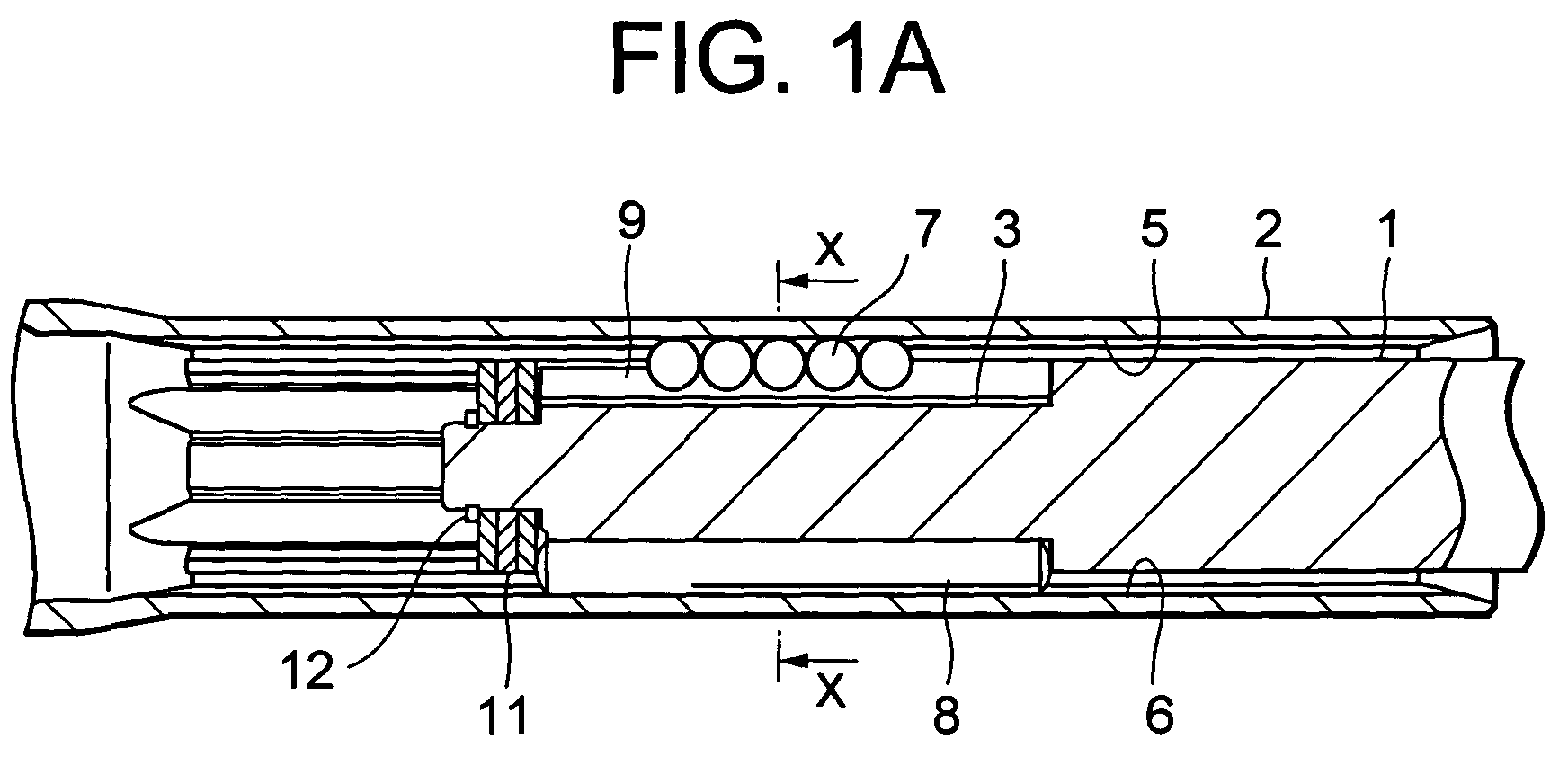
- Fig. 1A is a longitudinal cross sectional view of a telescopic shaft for vehicle steering according to a first embodiment of the present invention
- Fig. 1B is a transverse cross sectional view of the telescopic shaft, taken along the line X-X in Fig. 1A.
- the telescopic shaft for vehicle steering (hereinafter called the "telescopic shaft”) comprises a male shaft 1 and a female shaft 2 which are fitted to each other to be unrotatable and slidable.
- three grooves 3 are provided on the outer peripheral surface of the male shaft 1 at regular intervals of 120° in the circumferential direction to be extended in the axial direction.
- three grooves 5 are provided on the inner peripheral surface of the female shaft 2, which are extended in the axial direction at regular intervals (phase) of 120° in the circumferential direction.
- a plurality of spherical members 7 which are rigid bodies for rotating upon relative movement of the male and female shafts 1 and 2 in the axial direction are interposed to be rotatable.
- Each of the axial grooves 5 has substantially an arch-shaped or Gothic arch-shaped cross section.
- the axial groove 3 is constituted by a substantially flat bottom portion and substantially flat side surfaces each having a predetermined angle with respect to the bottom portion.
- the bottom portion and the side surfaces may have a predetermined angle therebetween or may be at right angles.
- a pair of raceway surface elements 9 which are formed of steel plates to be brought into contact with the spherical members 7 and a pair of elastic members 10 which are formed of rubber or the like for preloading the spherical members 7 against the male shaft 1 and the female shaft 2 through these raceway surface elements 9, respectively, are interposed.
- the steel plates for forming the pair of raceway surface elements 9 is separated right and left, and the contact portion between each of the raceway surface elements 9 and the spherical member 7 may be flat or curved, as shown in the drawing.
- the contact portion of the raceway surface element 9 is flat, as illustrated in the drawing, it is preferable that the contact portion of the raceway surface element 9 is substantially in parallel to a side surface of the axial groove 3 of the male shaft 1. That is, an angle which is formed by and between the contact portion of the raceway surface element 9 and the bottom portion of the groove 3 and an angle which is formed by and between each side surface of the groove 3 and the bottom portion of the groove 3 is substantially equal to each other.
- the pair of elastic members 10 may be separated from each of the corresponding raceway surface elements 9, or may be integrally bonded to the respective raceway surface element 9.
- a stopper plate 11 with an elastic member is disposed in an end portion of the male shaft 1, and this stopper plate 11 with the elastic member is fixed by a caulked (or clinched) portion 12. Slip-off of the spherical members 7, the columnar members 8, the raceway surface elements 9 and the elastic members 10 is prevented by the stopper plate with the elastic member.
- three axial grooves 4 are provided on the outer peripheral surface of the male shaft 1 at regular intervals of 120° in the circumferential direction.
- three axial grooves 6 are also provided on the inner peripheral surface of the female shaft 2, to be extended at regular intervals of 120° in the circumferential direction.
- a plurality of columnar members 8 which are rigid bodies for slidably moving upon relative movement of the male and female shafts 1 and 2 in the axial direction are interposed to be slidable with very small gap therebetween.
- Each of the axial grooves 4 and 6 has substantially an arch-shaped or Gothic arch-shaped cross section.
- the telescopic shaft having such a structure as described above, since the spherical members 7 are interposed between the male shaft 1 and the female shaft 2 inclusive of the raceway surface elements 9 and the spherical members 7 are preloaded by the elastic members 10 to the extent that no backlash is generated with respect to the female shaft 2, it is possible to securely prevent backlash between the male shaft 1 and the female shaft 2 when torque is not transmitted. At the same time, the male shaft 1 and the female shaft 2 can slide in the axial direction with a stable sliding load with no backlash when they are moved in the axial direction relatively to each other.
- the elastic members 10 when torque is transmitted, the elastic members 10 are elastically deformed to restrain the spherical members 7 in the circumferential direction between the male shaft 1 and the female shaft 2 inclusive of the raceway surface element 9. Meanwhile, the three columnar members 8 interposed between the male shaft 1 and the female shaft 2 mainly discharge the function of transmitting torque.
- the torque transmission as a whole can be performed in a state that the torque transmitted to the female shaft 2 through the raceway surface elements 9 and the input torque from the male shaft 1, the elastic members 10 and the spherical members 7 are in balance.
- the columnar members 8 are provided in addition to the spherical members 7, most load amount can be supported by the columnar members 8 when great torque is inputted. As a result, it is possible to reduce a contact pressure between the axial grooves 5 of the female shaft 2, the raceway surface elements 9 and the spherical members 7 so as to improve the durability of the shaft, and at the same time, when a torque load is great, to transmit the torque in a state of high rigidity.
- the spherical member 7 is preferably a ball of rigid body. It is also preferable that the columnar member 8 of rigid body is a needle roller.
- the needle roller 8 receives a load with a line contact, there can be obtained various advantages such that the contact pressure can be lowered, compared with the case with a ball which receives a load with a point contact. As a result, this arrangement is superior in the following points to a case in which all of the arrays are in ball rolling structure.
- the needle rollers play the essential role for torque transmission between the male shaft 1 and the female shaft 2, and are brought into sliding contact with the inner peripheral surface of the female shaft 2.
- This structure is superior to the conventional structure which employs spline fitting in the following respects.
- Fig. 2A is a transverse cross sectional view of a telescopic shaft for vehicle steering according to a first variation of the first embodiment of the present invention (corresponding to the transverse cross sectional view, taken along the line X-X in Fig. 1A).
- a pair of raceway surface elements 9 which are formed of steel plate to be brought into contact with spherical members 7 and a pair of elastic members 10 which are formed of rubber, or the like, for preloading the spherical members 7 against the male shaft 1 and the female shaft 2 through these raceway surface elements 9 are interposed between axial grooves 5 of the female shaft 1 and the spherical members 7. Also in this case, the mode of operation is the same as in the first embodiment described above.
- the axial groove 5 is constituted by a substantially flat bottom portion and substantially flat side surfaces each having a predetermined angle with respect to the bottom portion.
- the bottom portion and the side surface may have a predetermined angle therebetween or may be at right angles.
- the steel plates for forming the pair of raceway surface elements 9 are separated right and left, and the contact portion between each of the raceway surface elements 9 and the spherical members 7 may be flat or curved, as shown in the drawing.
- the contact portion of the raceway surface element 9 is flat, as illustrated in the drawing, it is preferable that the contact portion of the raceway surface element 9 is substantially in parallel to a side surface of the axial groove 5 of the female shaft 2. That is, an angle which is formed between the contact portion of the raceway surface element 9 and the bottom portion of the groove 5 and an angle which is formed between each side surface of the groove 5 and the bottom portion of the groove 5 are substantially equal to each other.
- the pair of elastic members 10 may be separated from the respectively corresponding raceway surface elements 9, or may be integrally bonded to the raceway surface elements 9.
- Fig. 2B is a transverse cross sectional view of a telescopic shaft for vehicle steering according to a second variation of the first embodiment of the present invention (corresponding to the transverse cross sectional view, taken along the line X-X in Fig. 1A).
- the pair of raceway surface elements 9 made of steel plates are formed to be arch-shaped along the curved surfaces of the spherical members 7, while the pair of elastic members 10 are formed to be thicker than those in the first embodiment. Also in this case, the mode of operation is the same as in the first embodiment described above.
- the axial groove 3 is constituted by a substantially flat bottom portion and substantially flat side surfaces each having an almost right angle with this bottom portion.
- the bottom portion and the side surface may be at right angle or may have a predetermined angle therebetween.
- the steel plates for forming the paired raceway surface elements 9 are separated right and left, and the contact portion between each of the raceway surface elements 9 and the spherical members 7 may be curved or flat, as shown in the drawing.
- the contact portion of the raceway surface element 9 is flat, unlike in the case illustrated in the drawing, it is preferable that the contact portion of the raceway surface element 9 is substantially in parallel to a side surface of the axial groove 3 of the male shaft 1. That is, an angle which is formed by and between the contact portion of the raceway surface element 9 and the bottom portion of the groove 3 and an angle which is formed by and between each side surface of the groove 3 and the bottom portion of the groove 3 are substantially equal to each other.
- the pair of elastic members 10 may be separated from the respectively corresponding raceway surface elements 9, or may be integrally bonded to the raceway surface elements 9.
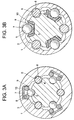
- Fig. 3A is a transverse cross sectional view of a telescopic shaft for vehicle steering according to a second embodiment of the present invention (corresponding to the transverse cross sectional view, taken along the line X-X in Fig. 1A).
- a pair of raceway surface elements 9 made of needle rollers which are brought into contact with spherical members 7 and a elastic member 10 which is formed of rubber, or the like, for preloading the spherical members 7 against the male shaft 1 and the female shaft 2 through these raceway surface elements 9 is interposed between axial grooves 5 of the female shaft 1 and the spherical members 7.
- the mode of operation is the same as in the first embodiment described above.
- the axial groove 5 is constituted by a substantially flat bottom portion and substantially flat side surfaces each having an almost right angle with respect to the bottom portion.
- the bottom portion and the side surface may have a predetermined angle therebetween or may be at right angle.
- the elastic member 10 is disposed only on the bottom portion of the axial groove 5 in the illustrated example, it may be disposed up to the side surfaces of the groove 5.
- One elastic member 10 may be provided singly or two separate ones may be provided to be corresponding to the raceway surface elements 9, respectively.
- the raceway surface elements in the second embodiment are a pair of needle rollers 9 (columnar members) which are disposed to have the central axes in parallel to the axial grooves 5 to be extended in the axial direction, several sizes of needle rollers 9 can be employed as the raceway surface elements, and a desired preload can be generated by controlling an interference. As a result, it is possible to reduce a fluctuation in the preload and the torsional rigidity caused by manufacturing errors (dimensional errors) of the male shaft 1, the female shaft 2 and the elastic members 10. It is also possible to achieve lower manufacturing cost by simplifying the form of the raceway surface element.
- Fig. 3B is a transverse cross sectional view of a telescopic shaft for vehicle steering according to the third embodiment of the present invention (corresponding to the transverse cross sectional view, taken along the line X-X in Fig. 1A).
- the raceway surface element 9 is formed of metal to take the form of a guide rail.
- the elastic member 10 is formed of a leaf spring which is integrally formed to be line symmetrical with both ends thereof folded back. Also in this case, the mode of operation is the same as in the first embodiment described above.
- the axial groove 3 is constituted by a substantially flat bottom portion and substantially flat side surfaces each having a predetermined angle with respect to the bottom portion.
- the bottom portion and the side surface may have a predetermined angle therebetween or may be at right angles.
- the paired raceway surface elements 9 are separated right and left, and the contact portion between each of the raceway surface elements 9 and the spherical members 7 may be curved or flat, as shown in the drawing.
- the contact portion of the raceway surface element 9 is flat, unlike in the case illustrated in the drawing, it is preferable that the contact portion of the raceway surface element 9 is substantially in parallel to the side surfaces of the axial groove 3 of the male shaft 1. That is, an angle which is formed by and between the contact portion of the raceway surface element 9 and the bottom portion of the groove 3 and an angle which is formed by and between each side surface of the groove 3 and the bottom portion of the groove 3 are substantially equal to each other.
- the elastic member 10 may be comprised of two pieces which are separated to be corresponding to the raceway surface elements 9, respectively.
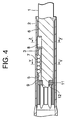
- Fig. 4 is a longitudinal cross sectional view of a telescopic shaft for vehicle steering according to a fourth embodiment of the present invention.
- Fig. 5A is a transverse cross sectional view of the telescopic shaft, taken along the line Y-Y in Fig. 4, and Fig. 5B is a transverse cross sectional view of the telescopic shaft, taken along the line Z-Z in Fig. 4.
- three axial grooves 3 are provided to be extended on the outer peripheral surface of the male shaft 1 at regular intervals of 120° in the circumferential direction.
- three axial grooves 5 are provided to be extended on the inner peripheral surface of the female shaft 2 at regular intervals of 120° in the circumferential direction.
- a plurality of spherical members 7 which are rigid bodies for rotating upon relative movement of the male and female shafts 1 and 2 in the axial direction are interposed to be rotatable.
- raceway surface elements 9 which are formed of steel plates to be brought into contact with the spherical members 7 and a pair of elastic members 10 which are formed of rubber, or the like, for preloading the spherical members 7 against the male shaft 1 and the female shaft 2 through these raceway surface elements 9 are interposed.
- the axial groove 3 is constituted by a substantially flat bottom portion and substantially flat side surfaces each having a predetermined angle with respect to the bottom portion.
- the bottom portion and the side surface may have a predetermined angle therebetween or may be at right angles.
- the steel plates for forming the paired raceway surface elements 9 are separated right and left, and the contact portion between each of the raceway surface elements 9 and the spherical members 7 may be curved or flat, as shown in the drawing.
- the contact portion of the raceway surface element 9 is flat, as illustrated in the drawing, it is preferable that the contact portion of the raceway surface element 9 is substantially in parallel to the side surface of the axial groove 3 of the male shaft 1. That is, it is preferable that an angle which is formed by and between the contact portion of the raceway surface element 9 and the bottom portion of the groove 3 and an angle which is formed by and between each side surface of the groove 3 and the bottom portion of the groove 3 are substantially equal to each other.
- the pair of elastic members 10 may be separated from the respectively corresponding raceway surface elements 9, or may be integrally bonded to the respective raceway surface elements 9.
- a stopper plate 11 with an elastic member is disposed in an end portion of the male shaft 1, and this stopper plate 11 with the elastic member 11 is fixed to an end portion of the male shaft 1 by a caulked (or clinched) portion 12. Slip-off of the spherical members 7, the raceway surface elements 9 an the elastic members 10 is prevented by this stopper plate with the elastic member.
- a plurality of columnar members 8 which are formed of rigid bodies and slide during a relative movement of both shafts 1 and 2 in the axial direction are interposed to be slidable between the axial grooves 4 and 6 which are formed concentrically with the axial grooves 3 and 5 described above.
- the axial groove 3 is comprised of a bottom portion and side surfaces each having a predetermined angle.
- Each of the axial grooves 5 has substantially an arch-shaped or Gothic arch-shaped cross section, and each of the axial grooves 4 and 6 has substantially an arch-shaped or Gothic arch-shaped cross section.
- the axial grooves 5 and the axial grooves 6 are concentric with each other and have substantially the same forms.
- the axial grooves 3 and the axial grooves 4 are, though being concentric with each other, different in form.
- a stopper plate 13 with an elastic member between the row of spherical members 7 and the columnar member 8. Interference between the spherical members 7 and the columnar member 8 is prevented by this stopper plate 13 with the elastic member.
- the load amount can be supported mostly by the columnar members 8 when great torque is inputted.
- the columnar members 8 are in contact with the male shaft 1 and the female shaft 2, it is possible to reduce the torsional torque to the spherical members 7 so as to suppress a lateral slide of the raceway surface elements 9. As a result, it is possible to prevent the hysteresis from being excessively great.
- the load amount can be supported mostly by the sliding members (columnar members) when great torque is inputted.
- the sliding members are in contact with the male shaft and the female shaft, it is possible to reduce the torsional torque to the rolling members (spherical members) so as to suppress a lateral slide of the raceway surface elements. As a result, it is possible to prevent the hysteresis from being excessively great.
Landscapes
- Engineering & Computer Science (AREA)
- General Engineering & Computer Science (AREA)
- Mechanical Engineering (AREA)
- Ocean & Marine Engineering (AREA)
- Chemical & Material Sciences (AREA)
- Combustion & Propulsion (AREA)
- Transportation (AREA)
- Steering Controls (AREA)
- Bearings For Parts Moving Linearly (AREA)
Abstract
According to the present invention, a rolling
element 7 for rotating upon relative movement of both
shafts 1 and 2 in the axial direction is disposed
between three pairs of axial grooves 3 and 5 which
are formed on the outer peripheral surface of the
male shaft 1 and on the inner peripheral surface of
the female shaft 2, respectively, a raceway surface
element 9 which is in contact with the rolling
element 7 and an elastic member 10 for pressurizing
the rolling element 7 against the male shaft 1 and
the female shaft 2 through the raceway surface
element 9 are interposed between the axial groove 3
on the male shaft side 1 and the rolling element 7,
and a sliding member 8 for slidably moving upon
relative movement of the both shafts 1 and 2 in the
axial direction is disposed between another three
pairs of axial grooves 4 and 6 which are formed on
the outer peripheral surface of the male shaft 1 and
on the inner peripheral surface of the female shaft 2,
respectively.
Description
The present invention relates to a telescopic
shaft for vehicle steering which is installed in a
steering shaft of a vehicle and in which a male shaft
and a female shaft are fitted to each other to be
mutually unrotatable and slidable.
A telescopic shaft of a steering mechanism of a
vehicle is required to have a property of absorbing
an axial displacement which is generated when the
vehicle is running and of preventing such
displacement or vibration from being propagated onto
a steering wheel. Further, the telescopic shaft is
also required to have a function of moving the
position of the steering wheel in the axial direction
and of adjusting this position in order to obtain an
optimal position for the driver to drive the vehicle.
In any of these cases, the telescopic shaft is
required to reduce rattling sound, to decrease
backlash feeling on the steering wheel, and to reduce
a sliding resistance during a sliding operation in
the axial direction.
For such reasons, conventionally, a male shaft
of the telescopic shaft is coated with nylon film and
grease is applied onto a sliding portion thereof, so
as to absorb or mitigate metallic noise, metallic
rattle and, at the same time, to reduce a sliding
resistance and backlash in the direction of rotation.
However, there is a case that abrasion of the
nylon film advances with use and the backlash in the
direction of rotation becomes great. Also, under the
high-temperature condition inside the engine room, a
nylon film is changed in volume, so that a sliding
resistance becomes conspicuously great or the
abrasion is notably quickened sometimes, and
resultantly, the backlash in the direction or
rotation may become great in such a case.
On that account, in Japanese Patent Application
Laid-Open No. 2001-50293, between at least one pair
of axial grooves respectively formed on the outer
peripheral surface of a male shaft and on the inner
peripheral surface of a female shaft, there is formed
rolling elements (spherical members) which are
rotated when both shafts are relatively rotated in
the axial direction.
Between the axial groove on the male shaft side
and the rolling elements (spherical members), a
raceway element which is in contact with the rolling
elements (spherical member) and an elastic member for
preloading the rolling element (spherical member)
against the male shaft and the female shaft through
this raceway element are interposed.
With this arrangement, since the rolling
element (spherical member) is preloaded against the
female shaft by the elastic member to the extent that
no backlash is generated when torque is not
transmitted (at the time of sliding), it is possible
to prevent backlash between the male shaft and the
female shaft, whereby the male shaft and the female
shaft can slide in the axial direction with a stable
sliding load without backlash.
Also, since it is arranged such that the
rolling element (spherical member) can be retained in
the circumferential direction by the elastic member
when torque is transmitted, the male shaft and the
female shaft can transmit the torque in a state of
high rigidity by preventing backlash in the direction
or rotation thereof.
However, in Japanese Patent Application Laid-Open
No. 2001-50293 described above, since the
rolling element (spherical member) is in point
contact with the axial groove of the female shaft and
the raceway surface element on the male shaft side,
there is sometimes generated a dent (or impression)
on the surface of the axial groove, or the like,
which is in contact with the spherical member if the
contact pressure becomes excessively great when the
torque load is great. As a result, an increased
fluctuation of the sliding load or deteriorated
torsional rigidity is brought about.
With an increase of the torsional torque, a
lateral slide of the raceway element with respect to
the male shaft may be increased so that hysteresis
becomes excessively great.
Further, an amount of preloading and the
torsional rigidity may be fluctuated due to a
manufacturing error (dimensional error) of each of
the male shaft, the female shaft, the elastic member,
and the raceway surface element.
The present invention has been contrived taking
such circumstances as described above into
consideration, and an object thereof is to provide a
telescopic shaft for vehicle steering which is
capable of achieving a stable sliding load and, at
the same time, preventing backlash in a direction of
rotation, thereby transmitting torque in a state of
high rigidity, with the improved durability and with
the function of preventing hysteresis from becoming
excessively great.
In order to achieve the above object, according
to the present invention, there is provided a
telescopic shaft for vehicle steering which is
installed in a steering shaft of a vehicle and in
which a male shaft and a female shaft are fitted to
each other to be unrotatable and slidable,
characterized in that:
According to the present invention, there is
also provided a telescopic shaft for vehicle steering
which is installed in a steering shaft of a vehicle
and in which a male shaft and a female shaft are
fitted to each other to be unrotatable and slidable,
characterized in that:
As described above, according to the telescopic
shaft for vehicle steering of the present invention,
since a columnar member serving as the sliding member
is provided, in addition to a spherical member
serving as the rolling element, when great torque is
inputted, most of the load amount can be supported by
the sliding member (columnar member). As a result,
it is possible to improve the durability of the shaft
by decreasing the contact pressure between the groove
extended in the axial direction of the male shaft or
the female shaft, the raceway element, and the
rolling element (spherical member). At the same time,
it is possible to transmit, when the torque load is
great, the torque in a state of high rigidity.
Also, since the sliding member (columnar
member) is in contact with the male shaft and the
female shaft, it is possible to reduce the torsional
torque toward the rolling element (spherical member)
and to prevent a lateral slide of the raceway surface
element. As a result, it is possible to suppress
hysteresis from being excessively great.
As seen from the above description, according
to the telescopic shaft for vehicle steering of the
present invention described above, it is possible to
realize a stable sliding load and, at the same time,
to prevent backlash in the direction of rotation
without fail, thereby transmitting the torque in a
state of high rigidity.
Further, according to the telescopic shaft for
vehicle steering of the present invention, it is
possible to make the raceway surface element the
columnar member which has the central axis thereof in
a line with the axial grooves. In this case, since
the raceway surface element is the columnar member
having the central axis thereof in a line with the
axial grooves, several sizes of columnar members can
be employed as the raceway surface elements, and a
desired preload can be generated by controlling an
interference. As a result, it is possible to reduce
a fluctuation in the preload and the torsional
rigidity which is caused by manufacturing errors
(dimensional errors) of the male shaft, the female
shaft and the elastic member. It is also possible to
achieve lower manufacturing cost by simplifying the
form of the raceway surface element.
A telescopic shaft for vehicle steering
according to an embodiment of the present invention
will be described below with reference to drawings.
Fig. 6 is a side view of a steering mechanism
of a vehicle in which a telescopic shaft for vehicle
steering according to an embodiment of the present
invention is applied.
In Fig. 6, the steering mechanism is
constituted by an upper steering shaft portion 120
(including a steering column 103 and a steering shaft
104 retained by the steering column 103 to be
rotatable) which is attached to a vehicle body-side
member 100 through an upper bracket 101 and a lower
bracket 102, a steering wheel 105 which is attached
to an upper end of the steering shaft 104, a lower
steering shaft portion 107 which is coupled to a
lower end of the steering shaft 104 through a
universal joint 106, a pinion shaft 109 which is
coupled to the lower steering shaft portion 107
through a steering shaft joint 108, a steering rack
shaft 112 coupled to the pinion shaft 109, and a
steering rack supporting member 113 which supports
the steering rack shaft 112 and is fixed to another
frame of the vehicle body through an elastic member
111.
In this case, the upper steering shaft portion
120 and the lower steering shaft portion 107 employ a
telescopic shaft for vehicle steering according to an
embodiment of the present invention (hereinafter
called the "telescopic shaft"). The lower steering
shaft portion 107 is formed by fitting a male shaft
and a female shaft to each other. Such a lower
steering shaft portion 107 is required to have the
property of absorbing an axial displacement which is
generated during the running of the vehicle so as not
to transmit the displacement or vibration onto the
steering wheel 105. Such a property is required for
a structure in which the vehicle body is in a subframe
structure so that the member 100 for fixing an
upper part of the steering mechanism is separately
provided from the frame 110 to which the steering
rack supporting member 113 is fixed, and the steering
rack supporting member 113 is fixed to the frame 110
through the elastic member 111 such as rubber. There
is also another case that an extending/contracting
function is required for an operator, in order to
connect the steering shaft joint 108 to the pinion
shaft 109, to once contract the telescopic shaft to
be fitted and connected to the pinion shaft 109.
Further, though the upper steering shaft 120 which is
provided in an upper part of the steering mechanism
is also formed by fitting the male shaft and the
female shaft to each other, such an upper steering
shaft portion 120 is required to have the function of
moving the position of the steering wheel 105 in the
axial direction and then adjusting the position so as
to obtain an optimal position for the driver to drive
the vehicle. In all the foregoing cases, the
telescopic shaft is required to have a property of
reducing rattling sound in the fitting portion,
decreasing backlash feeling on the steering wheel 105,
and reducing a sliding resistance during sliding
movement in the axial direction.
Fig. 1A is a longitudinal cross sectional view
of a telescopic shaft for vehicle steering according
to a first embodiment of the present invention, and
Fig. 1B is a transverse cross sectional view of the
telescopic shaft, taken along the line X-X in Fig. 1A.
As shown in Fig. 1A, the telescopic shaft for
vehicle steering (hereinafter called the "telescopic
shaft") comprises a male shaft 1 and a female shaft 2
which are fitted to each other to be unrotatable and
slidable.
As shown in Fig. 1B, three grooves 3 are
provided on the outer peripheral surface of the male
shaft 1 at regular intervals of 120° in the
circumferential direction to be extended in the axial
direction. To be corresponding thereto, on the inner
peripheral surface of the female shaft 2, there are
provided three grooves 5 which are extended in the
axial direction at regular intervals (phase) of 120°
in the circumferential direction.
Between the axial grooves 3 of the male shaft 1
and the respective axial grooves 5 of the female
shaft 2, a plurality of spherical members 7 (rolling
elements) which are rigid bodies for rotating upon
relative movement of the male and female shafts 1 and
2 in the axial direction are interposed to be rotatable.
Each of the axial grooves 5 has substantially an arch-shaped
or Gothic arch-shaped cross section.
Note that the axial groove 3 is constituted by
a substantially flat bottom portion and substantially
flat side surfaces each having a predetermined angle
with respect to the bottom portion. The bottom
portion and the side surfaces may have a
predetermined angle therebetween or may be at right
angles.
Between the axial groove 3 of the male shaft 1
and the spherical members 7, a pair of raceway
surface elements 9 which are formed of steel plates
to be brought into contact with the spherical members
7 and a pair of elastic members 10 which are formed
of rubber or the like for preloading the spherical
members 7 against the male shaft 1 and the female
shaft 2 through these raceway surface elements 9,
respectively, are interposed.
The steel plates for forming the pair of
raceway surface elements 9 is separated right and
left, and the contact portion between each of the
raceway surface elements 9 and the spherical member 7
may be flat or curved, as shown in the drawing. When
the contact portion of the raceway surface element 9
is flat, as illustrated in the drawing, it is
preferable that the contact portion of the raceway
surface element 9 is substantially in parallel to a
side surface of the axial groove 3 of the male shaft
1. That is, an angle which is formed by and between
the contact portion of the raceway surface element 9
and the bottom portion of the groove 3 and an angle
which is formed by and between each side surface of
the groove 3 and the bottom portion of the groove 3
is substantially equal to each other.
The pair of elastic members 10 may be separated
from each of the corresponding raceway surface
elements 9, or may be integrally bonded to the
respective raceway surface element 9.
Also, as shown in Fig. 1A, a stopper plate 11
with an elastic member is disposed in an end portion
of the male shaft 1, and this stopper plate 11 with
the elastic member is fixed by a caulked (or
clinched) portion 12. Slip-off of the spherical
members 7, the columnar members 8, the raceway
surface elements 9 and the elastic members 10 is
prevented by the stopper plate with the elastic
member.
As shown in Fig. 1B, three axial grooves 4 are
provided on the outer peripheral surface of the male
shaft 1 at regular intervals of 120° in the
circumferential direction. To be corresponding
thereto, on the inner peripheral surface of the
female shaft 2, there are also provided three axial
grooves 6 to be extended at regular intervals of 120°
in the circumferential direction.
Between the axial grooves 4 of the male shaft 1
and the corresponding axial grooves 6 of the female
shaft 2, a plurality of columnar members 8 (sliding
members) which are rigid bodies for slidably moving
upon relative movement of the male and female shafts
1 and 2 in the axial direction are interposed to be
slidable with very small gap therebetween. Each of
the axial grooves 4 and 6 has substantially an arch-shaped
or Gothic arch-shaped cross section.
With the telescopic shaft having such a
structure as described above, since the spherical
members 7 are interposed between the male shaft 1 and
the female shaft 2 inclusive of the raceway surface
elements 9 and the spherical members 7 are preloaded
by the elastic members 10 to the extent that no
backlash is generated with respect to the female
shaft 2, it is possible to securely prevent backlash
between the male shaft 1 and the female shaft 2 when
torque is not transmitted. At the same time, the
male shaft 1 and the female shaft 2 can slide in the
axial direction with a stable sliding load with no
backlash when they are moved in the axial direction
relatively to each other.
In the present embodiment, when torque is
transmitted, the elastic members 10 are elastically
deformed to restrain the spherical members 7 in the
circumferential direction between the male shaft 1
and the female shaft 2 inclusive of the raceway
surface element 9. Meanwhile, the three columnar
members 8 interposed between the male shaft 1 and the
female shaft 2 mainly discharge the function of
transmitting torque.
For example, when torque is inputted from the
male shaft 1, since preload of the elastic members 10
is applied in the initial stage, there is generated
no backlash and the reaction force against torque is
generated by the elastic members 10 to transmit the
torque. In this case, the torque transmission as a
whole can be performed in a state that the torque
transmitted to the female shaft 2 through the raceway
surface elements 9 and the input torque from the male
shaft 1, the elastic members 10 and the spherical
members 7 are in balance.
When the torque is further increased, a gap
between the male shaft 1 and the female shaft 2
through the columnar members 8 in the direction of
rotation disappears so that the columnar members 8
transmit an incremental portion of the torque
subsequent thereto from the male shaft 1 to the
female shaft 2. For this reason, it is possible to
securely prevent backlash in the direction of
rotation between the male shaft 1 and the female
shaft 2 and to transmit the torque in a state of high
rigidity.
From the above description, according to the
present embodiment, since the columnar members 8 are
provided in addition to the spherical members 7, most
load amount can be supported by the columnar members
8 when great torque is inputted. As a result, it is
possible to reduce a contact pressure between the
axial grooves 5 of the female shaft 2, the raceway
surface elements 9 and the spherical members 7 so as
to improve the durability of the shaft, and at the
same time, when a torque load is great, to transmit
the torque in a state of high rigidity.
Moreover, since the columnar members 8 are in
contact with the male shaft 1 and the female shaft 2,
it is possible to reduce the torsional torque toward
the spherical members 7 and to suppress lateral slide
of the raceway surface elements 9. As a result, it
is possible to prevent the hysteresis from being
excessively great.
As described above, according to the present
embodiment, it is possible to realize a stable
sliding load and, at the same time, to securely
prevent backlash in the direction of rotation,
thereby transmit the torque in a state of high
rigidity.
Note that the spherical member 7 is preferably
a ball of rigid body. It is also preferable that the
columnar member 8 of rigid body is a needle roller.
Since the columnar member (hereinafter called
the needle roller) 8 receives a load with a line
contact, there can be obtained various advantages
such that the contact pressure can be lowered,
compared with the case with a ball which receives a
load with a point contact. As a result, this
arrangement is superior in the following points to a
case in which all of the arrays are in ball rolling
structure.
- The attenuating performance in the sliding portion is great, compared with that in the ball rolling structure. As a result, the vibration absorbing performance is high.
- Since the needle roller is in contact with the male shaft and the female shaft at a small part, a fluctuation in sliding load can be kept low, and a vibration due to this fluctuation is not transmitted to the steering.
- If the same torque is to be transmitted, the contact pressure can be kept lower in the needle roller structure. As a result, the length of the shaft in the axial direction can be reduced so that the space can be used effectively.
- If the same torque is to be transmitted, the contact pressure can be kept lower in the needle roller structure. As a result, there is no longer required an additional process for hardening the surfaces of the axial grooves of the female shaft by thermal treatment or the like.
- The number of constituent parts can be reduced.
- The assembling performance can be improved.
- The assembling cost can be reduced.
As described above, the needle rollers play the
essential role for torque transmission between the
male shaft 1 and the female shaft 2, and are brought
into sliding contact with the inner peripheral
surface of the female shaft 2. This structure is
superior to the conventional structure which employs
spline fitting in the following respects.
- The needle rollers are manufactured in mass production, and can be manufactured at very low cost.
- The needle rollers are polished after being subjected to the thermal treatment, so that they have high surface rigidity and excellent wear resistance.
- Since the needle rollers have been polished, they have fine surface roughness and a low coefficient of friction in a sliding movement. As a result, the sliding load can be kept low.
- Since the length or the layout of the needle rollers can be changed in accordance with the condition of use, the needle rollers can be used in various applications without changing the design concept.
- There is a case in which the coefficient of friction at sliding is required to be further lowered, depending on the condition of use. In such a case, the sliding characteristics can be changed only by subjecting the needle rollers to the surface treatment. As a result, the needle rollers can be used in various applications without changing the design concept.
- Since needle rollers having different outer diameters by several microns can be manufactured at low cost, the gap among the male shaft, the needle rollers, and the female shaft can be minimized by selecting a diameter of the needle rollers. As a result, the rigidity of the shaft in the torsional direction can be improved easily.
Fig. 2A is a transverse cross sectional view of
a telescopic shaft for vehicle steering according to
a first variation of the first embodiment of the
present invention (corresponding to the transverse
cross sectional view, taken along the line X-X in Fig.
1A).
In this variation, a pair of raceway surface
elements 9 which are formed of steel plate to be
brought into contact with spherical members 7 and a
pair of elastic members 10 which are formed of rubber,
or the like, for preloading the spherical members 7
against the male shaft 1 and the female shaft 2
through these raceway surface elements 9 are
interposed between axial grooves 5 of the female
shaft 1 and the spherical members 7. Also in this
case, the mode of operation is the same as in the
first embodiment described above.
Note that the axial groove 5 is constituted by
a substantially flat bottom portion and substantially
flat side surfaces each having a predetermined angle
with respect to the bottom portion. The bottom
portion and the side surface may have a predetermined
angle therebetween or may be at right angles.
The steel plates for forming the pair of
raceway surface elements 9 are separated right and
left, and the contact portion between each of the
raceway surface elements 9 and the spherical members
7 may be flat or curved, as shown in the drawing.
When the contact portion of the raceway surface
element 9 is flat, as illustrated in the drawing, it
is preferable that the contact portion of the raceway
surface element 9 is substantially in parallel to a
side surface of the axial groove 5 of the female
shaft 2. That is, an angle which is formed between
the contact portion of the raceway surface element 9
and the bottom portion of the groove 5 and an angle
which is formed between each side surface of the
groove 5 and the bottom portion of the groove 5 are
substantially equal to each other.
The pair of elastic members 10 may be separated
from the respectively corresponding raceway surface
elements 9, or may be integrally bonded to the
raceway surface elements 9.
Fig. 2B is a transverse cross sectional view of
a telescopic shaft for vehicle steering according to
a second variation of the first embodiment of the
present invention (corresponding to the transverse
cross sectional view, taken along the line X-X in Fig.
1A).
In this variation, the pair of raceway surface
elements 9 made of steel plates are formed to be
arch-shaped along the curved surfaces of the
spherical members 7, while the pair of elastic
members 10 are formed to be thicker than those in the
first embodiment. Also in this case, the mode of
operation is the same as in the first embodiment
described above.
The axial groove 3 is constituted by a
substantially flat bottom portion and substantially
flat side surfaces each having an almost right angle
with this bottom portion. The bottom portion and the
side surface may be at right angle or may have a
predetermined angle therebetween.
The steel plates for forming the paired raceway
surface elements 9 are separated right and left, and
the contact portion between each of the raceway
surface elements 9 and the spherical members 7 may be
curved or flat, as shown in the drawing. When the
contact portion of the raceway surface element 9 is
flat, unlike in the case illustrated in the drawing,
it is preferable that the contact portion of the
raceway surface element 9 is substantially in
parallel to a side surface of the axial groove 3 of
the male shaft 1. That is, an angle which is formed
by and between the contact portion of the raceway
surface element 9 and the bottom portion of the
groove 3 and an angle which is formed by and between
each side surface of the groove 3 and the bottom
portion of the groove 3 are substantially equal to
each other.
The pair of elastic members 10 may be separated
from the respectively corresponding raceway surface
elements 9, or may be integrally bonded to the
raceway surface elements 9.
Fig. 3A is a transverse cross sectional view of
a telescopic shaft for vehicle steering according to
a second embodiment of the present invention
(corresponding to the transverse cross sectional view,
taken along the line X-X in Fig. 1A).
In the second embodiment, a pair of raceway
surface elements 9 made of needle rollers which are
brought into contact with spherical members 7 and a
elastic member 10 which is formed of rubber, or the
like, for preloading the spherical members 7 against
the male shaft 1 and the female shaft 2 through these
raceway surface elements 9 is interposed between
axial grooves 5 of the female shaft 1 and the
spherical members 7. In this case also, the mode of
operation is the same as in the first embodiment
described above.
Note that the axial groove 5 is constituted by
a substantially flat bottom portion and substantially
flat side surfaces each having an almost right angle
with respect to the bottom portion. The bottom
portion and the side surface may have a predetermined
angle therebetween or may be at right angle.
Though the elastic member 10 is disposed only
on the bottom portion of the axial groove 5 in the
illustrated example, it may be disposed up to the
side surfaces of the groove 5. One elastic member 10
may be provided singly or two separate ones may be
provided to be corresponding to the raceway surface
elements 9, respectively.
Since the raceway surface elements in the
second embodiment are a pair of needle rollers 9
(columnar members) which are disposed to have the
central axes in parallel to the axial grooves 5 to be
extended in the axial direction, several sizes of
needle rollers 9 can be employed as the raceway
surface elements, and a desired preload can be
generated by controlling an interference. As a
result, it is possible to reduce a fluctuation in the
preload and the torsional rigidity caused by
manufacturing errors (dimensional errors) of the male
shaft 1, the female shaft 2 and the elastic members
10. It is also possible to achieve lower
manufacturing cost by simplifying the form of the
raceway surface element.
Fig. 3B is a transverse cross sectional view of
a telescopic shaft for vehicle steering according to
the third embodiment of the present invention
(corresponding to the transverse cross sectional view,
taken along the line X-X in Fig. 1A).
In the third embodiment, the raceway surface
element 9 is formed of metal to take the form of a
guide rail. The elastic member 10 is formed of a
leaf spring which is integrally formed to be line
symmetrical with both ends thereof folded back. Also
in this case, the mode of operation is the same as in
the first embodiment described above.
Note that the axial groove 3 is constituted by
a substantially flat bottom portion and substantially
flat side surfaces each having a predetermined angle
with respect to the bottom portion. The bottom
portion and the side surface may have a predetermined
angle therebetween or may be at right angles.
The paired raceway surface elements 9 are
separated right and left, and the contact portion
between each of the raceway surface elements 9 and
the spherical members 7 may be curved or flat, as
shown in the drawing. When the contact portion of
the raceway surface element 9 is flat, unlike in the
case illustrated in the drawing, it is preferable
that the contact portion of the raceway surface
element 9 is substantially in parallel to the side
surfaces of the axial groove 3 of the male shaft 1.
That is, an angle which is formed by and between the
contact portion of the raceway surface element 9 and
the bottom portion of the groove 3 and an angle which
is formed by and between each side surface of the
groove 3 and the bottom portion of the groove 3 are
substantially equal to each other.
In addition, the elastic member 10 may be
comprised of two pieces which are separated to be
corresponding to the raceway surface elements 9,
respectively.
Fig. 4 is a longitudinal cross sectional view
of a telescopic shaft for vehicle steering according
to a fourth embodiment of the present invention.
Fig. 5A is a transverse cross sectional view of
the telescopic shaft, taken along the line Y-Y in Fig.
4, and Fig. 5B is a transverse cross sectional view
of the telescopic shaft, taken along the line Z-Z in
Fig. 4.
In the present embodiment, as shown in Fig. 5A,
three axial grooves 3 are provided to be extended on
the outer peripheral surface of the male shaft 1 at
regular intervals of 120° in the circumferential
direction. To be corresponding thereto, there are
provided three axial grooves 5 to be extended on the
inner peripheral surface of the female shaft 2 at
regular intervals of 120° in the circumferential
direction.
Between the axial groove 3 of the male shaft 1
and the axial groove 5 of the female shaft 2, a
plurality of spherical members 7 (rolling elements)
which are rigid bodies for rotating upon relative
movement of the male and female shafts 1 and 2 in the
axial direction are interposed to be rotatable.
Between the axial groove 3 of the male shaft 1
and the spherical members 7, a pair of raceway
surface elements 9 which are formed of steel plates
to be brought into contact with the spherical members
7 and a pair of elastic members 10 which are formed
of rubber, or the like, for preloading the spherical
members 7 against the male shaft 1 and the female
shaft 2 through these raceway surface elements 9 are
interposed.
The axial groove 3 is constituted by a
substantially flat bottom portion and substantially
flat side surfaces each having a predetermined angle
with respect to the bottom portion. The bottom
portion and the side surface may have a predetermined
angle therebetween or may be at right angles.
The steel plates for forming the paired raceway
surface elements 9 are separated right and left, and
the contact portion between each of the raceway
surface elements 9 and the spherical members 7 may be
curved or flat, as shown in the drawing. When the
contact portion of the raceway surface element 9 is
flat, as illustrated in the drawing, it is preferable
that the contact portion of the raceway surface
element 9 is substantially in parallel to the side
surface of the axial groove 3 of the male shaft 1.
That is, it is preferable that an angle which is
formed by and between the contact portion of the
raceway surface element 9 and the bottom portion of
the groove 3 and an angle which is formed by and
between each side surface of the groove 3 and the
bottom portion of the groove 3 are substantially
equal to each other.
The pair of elastic members 10 may be separated
from the respectively corresponding raceway surface
elements 9, or may be integrally bonded to the
respective raceway surface elements 9.
As shown in Fig. 4, a stopper plate 11 with an
elastic member is disposed in an end portion of the
male shaft 1, and this stopper plate 11 with the
elastic member 11 is fixed to an end portion of the
male shaft 1 by a caulked (or clinched) portion 12.
Slip-off of the spherical members 7, the raceway
surface elements 9 an the elastic members 10 is
prevented by this stopper plate with the elastic
member.
Further, in the present embodiment, as shown in
Fig. 5B, a plurality of columnar members 8 (sliding
members) which are formed of rigid bodies and slide
during a relative movement of both shafts 1 and 2 in
the axial direction are interposed to be slidable
between the axial grooves 4 and 6 which are formed
concentrically with the axial grooves 3 and 5
described above.
The axial groove 3 is comprised of a bottom
portion and side surfaces each having a predetermined
angle. Each of the axial grooves 5 has substantially
an arch-shaped or Gothic arch-shaped cross section,
and each of the axial grooves 4 and 6 has
substantially an arch-shaped or Gothic arch-shaped
cross section.
Accordingly, the axial grooves 5 and the axial
grooves 6 are concentric with each other and have
substantially the same forms. On the other hand, the
axial grooves 3 and the axial grooves 4 are, though
being concentric with each other, different in form.
As shown in Fig. 4, there is provided a stopper
plate 13 with an elastic member between the row of
spherical members 7 and the columnar member 8.
Interference between the spherical members 7 and the
columnar member 8 is prevented by this stopper plate
13 with the elastic member.
As seen from the above description, according
to the present embodiment, since there are provided
the columnar members 8 in addition to the spherical
members 7, the load amount can be supported mostly by
the columnar members 8 when great torque is inputted.
As a result, it is possible to improve the durability
of the shaft by reducing a contact pressure between
the axial grooves 5 of the female shaft 2, the
raceway elements 9 and the spherical members 7. At
the same time, it is possible to transmit the torque
in a state of high rigidity when the torque load is
great.
Also, since the columnar members 8 are in
contact with the male shaft 1 and the female shaft 2,
it is possible to reduce the torsional torque to the
spherical members 7 so as to suppress a lateral slide
of the raceway surface elements 9. As a result, it
is possible to prevent the hysteresis from being
excessively great.
As described above, according to the present
embodiment, it is possible to realize a stable
sliding load and to securely prevent backlash in the
direction of rotation, whereby the torque can be
transmitted in a state of high rigidity.
It should be noted that the present invention
is not limited to the foregoing embodiments, but can
be altered in various manners.
As described above, according to the present
invention, since there are provided the sliding
members (columnar members) in addition to the rolling
elements (spherical members), the load amount can be
supported mostly by the sliding members (columnar
members) when great torque is inputted. As a result,
it is possible to improve the durability of the shaft
by reducing a contact pressure between the axial
grooves of the male shaft or the female shaft, the
raceway elements and the rolling elements (spherical
members). At the same time, it is possible to
transmit the torque in a state of high rigidity when
the torque load is great.
Also, since the sliding members (columnar
members) are in contact with the male shaft and the
female shaft, it is possible to reduce the torsional
torque to the rolling members (spherical members) so
as to suppress a lateral slide of the raceway surface
elements. As a result, it is possible to prevent the
hysteresis from being excessively great.
As described above, according to the present
invention, it is possible to realize a stable sliding
load and to securely prevent backlash in the
direction of rotation, whereby the torque can be
transmitted in a state of high rigidity.
Claims (3)
- A telescopic shaft for vehicle steering which is installed in a steering shaft of a vehicle and in which a male shaft and a female shaft are fitted to each other to be unrotatable and slidable, characterized in that:rolling elements for rotating upon relative movement of said both shafts in the axial direction are disposed between at least one pair of grooves which are extended in the axial direction and respectively formed on the outer peripheral surface of said male shaft and on the inner peripheral surface of said female shaft;a raceway surface element which is in contact with said rolling elements and an elastic member for preloading said rolling elements against said male shaft and said female shaft through said raceway surface element is interposed between said groove extended in the axial direction on said male shaft side or said female shaft side and said rolling element; anda sliding member for slidably moving upon relative movement of said both shafts in the axial direction is disposed between at least another one pair of grooves which are extended in the axial direction and respectively formed on the outer peripheral surface of said male shaft and on the inner peripheral surface of said female shaft.
- A telescopic shaft for vehicle steering which is installed in a steering shaft of a vehicle and in which a male shaft and a female shaft are fitted to each other to be unrotatable and slidable, characterized in that:rolling elements for rotating upon relative movement of said both shafts in the axial direction are disposed between at least one pair of grooves which are extended in the axial direction and respectively formed on the outer peripheral surface of said male shaft and on the inner peripheral surface of said female shaft;a raceway surface element which is in contact with said rolling elements and an elastic member for preloading said rolling element against said male shaft and said female shaft through said raceway surface element are interposed between said groove extended in the axial direction on said male shaft side or said female shaft side and said rolling elements; anda sliding member for slidably moving upon relative movement of said both shafts in the axial direction is disposed to be concentric with at least said one pair of grooves extended in the axial direction between at least another pair of grooves which are extended in the axial direction and respectively formed on the outer peripheral surface of said male shaft and on the inner peripheral surface of said female shaft.
- A telescopic shaft for vehicle steering according to claim 1 or 2, wherein said raceway surface element is a columnar member which has the central axis thereof in parallel to said axial grooves.
Applications Claiming Priority (3)
| Application Number | Priority Date | Filing Date | Title |
|---|---|---|---|
| JP2002348214 | 2002-11-29 | ||
| JP2002348214 | 2002-11-29 | ||
| PCT/JP2003/015222 WO2004050453A1 (en) | 2002-11-29 | 2003-11-28 | Telescoping shaft for vehicle steering |
Publications (2)
| Publication Number | Publication Date |
|---|---|
| EP1566324A1 true EP1566324A1 (en) | 2005-08-24 |
| EP1566324A4 EP1566324A4 (en) | 2007-08-01 |
Family
ID=32462905
Family Applications (1)
| Application Number | Title | Priority Date | Filing Date |
|---|---|---|---|
| EP03812333A Withdrawn EP1566324A4 (en) | 2002-11-29 | 2003-11-28 | Telescoping shaft for vehicle steering |
Country Status (6)
| Country | Link |
|---|---|
| US (1) | US7416216B2 (en) |
| EP (1) | EP1566324A4 (en) |
| JP (1) | JP4419841B2 (en) |
| CN (1) | CN100460259C (en) |
| AU (1) | AU2003302651A1 (en) |
| WO (1) | WO2004050453A1 (en) |
Cited By (9)
| Publication number | Priority date | Publication date | Assignee | Title |
|---|---|---|---|---|
| WO2007045581A1 (en) * | 2005-10-21 | 2007-04-26 | Schaeffler Kg | Antifriction bearing for longitudinal motions with a limited sliding path |
| DE102006058999A1 (en) * | 2006-12-14 | 2008-06-19 | Bayerische Motoren Werke Ag | Torque transfer device comprises coaxial inner and outer tubes with longitudinal grooves which form seatings for at least two rows of ball bearings, wire cushion pads being positioned between bearings and outer tube |
| WO2009138070A1 (en) * | 2008-05-15 | 2009-11-19 | Neumayer Tekfor Holding Gmbh | Displacement unit |
| WO2011144715A1 (en) * | 2010-05-20 | 2011-11-24 | Zf Systemes De Direction Nacam, S.A.S. | Ball-type coupling device for coupling two sliding shafts with pivoting support |
| US8075412B2 (en) | 2008-06-20 | 2011-12-13 | Neumayer Tekfor Holding Gmbh | Displacement unit |
| CN103016703A (en) * | 2012-12-31 | 2013-04-03 | 长城汽车股份有限公司 | Control mechanism of manual transmission |
| WO2016042342A1 (en) * | 2014-09-19 | 2016-03-24 | Trw Limited | Improvements to steering column assemblies |
| WO2017001308A1 (en) * | 2015-06-30 | 2017-01-05 | Robert Bosch Automotive Steering Gmbh | Intermediate steering shaft for a motor vehicle, and method for operating an intermediate steering shaft for a motor vehicle |
| EP3490748A4 (en) * | 2016-10-31 | 2019-08-28 | Nanjing Chervon Industry Co., Ltd. | ALTERNATIVE TOOL HAVING LINEAR BALL RAILS |
Families Citing this family (32)
| Publication number | Priority date | Publication date | Assignee | Title |
|---|---|---|---|---|
| DE10297302B4 (en) * | 2001-10-01 | 2012-07-12 | Nsk Ltd. | Telescopic shaft for a vehicle steering |
| US7322607B2 (en) * | 2002-06-11 | 2008-01-29 | Nsk Ltd. | Telescopic shaft for steering vehicle and telescopic shaft for steering vehicle with cardan shaft coupling |
| JP4196630B2 (en) * | 2002-10-02 | 2008-12-17 | 日本精工株式会社 | Telescopic shaft for vehicle steering |
| CN100460259C (en) * | 2002-11-29 | 2009-02-11 | 日本精工株式会社 | Telescopic shaft for vehicle steering |
| JP4190905B2 (en) * | 2003-02-06 | 2008-12-03 | 日本精工株式会社 | Vehicle steering device |
| JPWO2005002947A1 (en) * | 2003-07-02 | 2006-08-10 | 日本精工株式会社 | Telescopic shaft for vehicle steering |
| US20070157754A1 (en) * | 2004-01-27 | 2007-07-12 | Nsk Ltd. | Telescopic shaft for vehicle steering |
| FR2875279B1 (en) * | 2004-09-14 | 2006-11-24 | Nacam France Sas | JOINT HOLDING BALL JOINT DEVICE OF TWO SLIDING TREES |
| US7914238B2 (en) * | 2004-09-20 | 2011-03-29 | Anthony John Spencer Spearing | Free standing support |
| JP4770193B2 (en) * | 2005-02-16 | 2011-09-14 | 日本精工株式会社 | Telescopic shaft for vehicle steering |
| JP4271176B2 (en) * | 2005-09-15 | 2009-06-03 | 本田技研工業株式会社 | Vehicle steering device |
| JP4921762B2 (en) * | 2005-09-30 | 2012-04-25 | 株式会社ジェイテクト | Telescopic shaft and telescopic shaft for vehicle steering |
| DK176810B1 (en) * | 2006-09-07 | 2009-10-12 | Falck Schmidt Defence Systems | Telescopic mast with reduced veil |
| JP2009029301A (en) * | 2007-07-27 | 2009-02-12 | Jtekt Corp | Telescopic shaft for vehicle steering and vehicle steering apparatus including the same |
| US8398496B2 (en) * | 2008-06-20 | 2013-03-19 | Zf Systemes De Direction Nacam, S.A.S. | Ball coupling device with hinged connection for two sliding shafts |
| CN103982559B (en) * | 2008-06-20 | 2017-05-10 | 采埃孚转向机系统纳凯姆联合股份公司 | Spherical hinged connection device for two sliding shafts |
| JP5544855B2 (en) | 2009-12-10 | 2014-07-09 | 株式会社ジェイテクト | Propeller shaft |
| US8894025B2 (en) * | 2012-08-30 | 2014-11-25 | Tien Hsin Industries Co., Ltd. | Multi-position adjustable height seat post |
| TWM456972U (en) * | 2013-01-24 | 2013-07-11 | Taiwan Hodaka Ind Co Ltd | Inner tube and outer tube direction restraining mechanism of bicycle seat tube |
| US8915521B2 (en) * | 2013-03-15 | 2014-12-23 | Steering Solutions Ip Holding Corporation | Steering column telescoping bushing with roller springs |
| BE1022076B1 (en) * | 2014-01-29 | 2016-02-15 | Cockerill Maintenance & Ingenierie Sa | IMPACT MITIGATION DEVICE |
| US10330141B2 (en) * | 2014-07-03 | 2019-06-25 | Nsk Ltd. | Extensible rotation transmission shaft |
| WO2016029301A1 (en) * | 2014-08-26 | 2016-03-03 | Nine Point Eight Inc. | Systems and methods for supporting telescoping elements |
| GB201420942D0 (en) * | 2014-11-25 | 2015-01-07 | Trw Ltd | Improvements to steering column assemblies |
| US10086865B2 (en) * | 2015-01-14 | 2018-10-02 | Nsk Ltd | Steering device |
| US10415646B2 (en) * | 2016-09-16 | 2019-09-17 | Steering Solutions Ip Holding Corporation | Telescoping roller I-shaft and method of assembly |
| DE102016218830A1 (en) * | 2016-09-29 | 2018-03-29 | Aktiebolaget Skf | unit |
| FR3088889B1 (en) * | 2018-11-23 | 2020-11-27 | Robert Bosch Automotive Steering Vendome | Coupling device between two coaxial shafts, in particular for a motor vehicle steering column |
| IT201900000145A1 (en) * | 2019-01-08 | 2020-07-08 | Comer Ind Spa | SHAFT-HUB CONNECTION SYSTEM WITH ANGULAR CLEARANCE FOR BIDIRECTIONAL TRANSMISSION OF THE DRIVE TORQUE. |
| CN110371177B (en) * | 2019-06-11 | 2020-07-28 | 潍柴动力股份有限公司 | Steering transmission shaft |
| US11731684B1 (en) * | 2022-02-24 | 2023-08-22 | Steering Solutions Ip Holding Corporation | Recirculating ball track telescope interface assembly for steering column |
| CN117341801B (en) * | 2023-10-31 | 2026-04-14 | 中国重汽集团济南动力有限公司 | Circulation ball type steering telescopic shaft with automatic gap eliminating structure |
Family Cites Families (82)
| Publication number | Priority date | Publication date | Assignee | Title |
|---|---|---|---|---|
| US2607257A (en) | 1950-08-30 | 1952-08-19 | Minshall Estey Organ Inc | Organ key loading device |
| US3169407A (en) * | 1962-02-28 | 1965-02-16 | Westinghouse Air Brake Co | Motion converting device |
| JPS4519207Y1 (en) | 1965-01-02 | 1970-08-05 | ||
| US3356424A (en) | 1965-04-30 | 1967-12-05 | Gen Motors Corp | Ball spline assembly |
| US3392599A (en) | 1966-12-30 | 1968-07-16 | Gen Motors Corp | Energy absorbing device |
| US3444753A (en) | 1967-12-14 | 1969-05-20 | Bendix Corp | No-lash axially movable steering column |
| US3604285A (en) | 1970-04-06 | 1971-09-14 | Saab Scania Ab | Energy-absorbing device and method of making the same |
| CH553350A (en) | 1972-06-20 | 1974-08-30 | Betrix Claude | DEVICE FOR GUIDING THE AXIAL DISPLACEMENT OF A CYLINDRICAL ORGAN. |
| DE2461289B1 (en) * | 1974-12-23 | 1975-11-13 | Loehr & Bromkamp Gmbh | Constant velocity swivel |
| DE2804778C3 (en) * | 1978-02-04 | 1982-04-08 | Uni-Cardan Ag, 5200 Siegburg | Telescopic drive shaft |
| US4384861A (en) | 1979-10-10 | 1983-05-24 | Firma LWM Lemforder Gelenkwellen GmbH | Universal joint shaft, particularly for a steering column of motor vehicles |
| US4357137A (en) | 1980-08-18 | 1982-11-02 | Arinc Research Corporation | Shaft coupling |
| US4500141A (en) | 1982-09-13 | 1985-02-19 | Daugherty Estes M | Drill steel idler guide |
| US4509386A (en) * | 1982-11-15 | 1985-04-09 | General Motors Corporation | Lash-free telescopic steering shaft assembly and method of making the assembly |
| SE450153B (en) * | 1985-01-22 | 1987-06-09 | Ffv Affersverket | TELESCOPE CONTROL, SPECIAL FOR TRANSMISSION OF TORQUE |
| GB8513070D0 (en) | 1985-05-23 | 1985-06-26 | Brd Co Ltd | Sliding splined joint |
| AT384405B (en) | 1985-07-22 | 1987-11-10 | Supervis Ets | LENGTH-CHANGEABLE STEERING SPINDLE FOR STEERING DEVICES IN MOTOR VEHICLES |
| JPS62244758A (en) | 1986-04-18 | 1987-10-26 | Koyo Seiko Co Ltd | Position adjusting device for steering handle |
| SE461605B (en) | 1987-03-12 | 1990-03-05 | Ffv Autotech Ab | Torque transmitting telescopic shaft with overload protection |
| DE3730393C2 (en) * | 1987-09-10 | 1994-01-13 | Lemfoerder Metallwaren Ag | Steering shaft for motor vehicles, consisting of axially displaceable shaft parts |
| JPH0714109Y2 (en) | 1988-03-15 | 1995-04-05 | 光洋精工株式会社 | Power steering device |
| US5184978A (en) * | 1990-04-16 | 1993-02-09 | Gkn Automotive, Inc. | Telescopic triplan universal joint |
| JPH0443522U (en) | 1990-08-16 | 1992-04-14 | ||
| FR2669693A1 (en) | 1990-11-23 | 1992-05-29 | Nacam | EXTENDABLE COUPLING PERFECTED TO SOLIDARIZE IN ROTATION TWO TREES WITH INTEGRATED SECURITY SYSTEM AND ITS APPLICATION IN PARTICULAR TO DIRECTIONS OF AUTOMOBILES. |
| JP2538390Y2 (en) | 1991-04-22 | 1997-06-11 | 富士機工株式会社 | Telescopic shaft |
| US5235734A (en) | 1991-11-04 | 1993-08-17 | Itt Corporation | Collapsible steering shaft apparatus and method of making same |
| US5236853A (en) * | 1992-02-21 | 1993-08-17 | United Microelectronics Corporation | Self-aligned double density polysilicon lines for ROM and EPROM |
| US5460574A (en) | 1993-08-31 | 1995-10-24 | Trw Inc. | Variable length shaft assembly with a lash bushing |
| CN2231998Y (en) * | 1995-05-24 | 1996-07-31 | 常熟市特种电器厂 | Steel ball type steering collapsible shaft |
| US5542343A (en) | 1995-09-26 | 1996-08-06 | Trw Inc. | Power steering assembly with damping ring |
| DE19538303A1 (en) | 1995-10-14 | 1997-04-17 | Zahnradfabrik Friedrichshafen | Steering column of a motor vehicle |
| JP3671571B2 (en) | 1996-02-29 | 2005-07-13 | 株式会社デンソー | Power transmission device |
| US5709605A (en) | 1996-12-23 | 1998-01-20 | General Motors Corporation | Shaft coupling |
| FR2759436B1 (en) * | 1997-02-11 | 1999-04-30 | Pierre Guimbretiere | HOMOCINETIC SLIDING JOINT WITH TRIPOD |
| DE19735443A1 (en) | 1997-08-16 | 1999-02-18 | Schaeffler Waelzlager Ohg | Torque-transmitting shaft for profiled pipe |
| DE19801166C2 (en) * | 1998-01-15 | 2001-06-28 | Micro Compact Car Smart Gmbh | Motor vehicle steering shaft with two shaft sections |
| DE19820291B4 (en) | 1998-05-07 | 2006-06-14 | Willi Elbe Gelenkwellen Gmbh & Co. Kg | Multiple telescopic steering shaft with blocking device |
| DE19824477A1 (en) * | 1998-05-30 | 1999-12-02 | Daimler Chrysler Ag | Telescopic steering shaft for vehicle |
| JP3659033B2 (en) | 1998-11-24 | 2005-06-15 | 日本精工株式会社 | Shock absorbing electric power steering system |
| JP2000205288A (en) | 1999-01-12 | 2000-07-25 | Koyo Seiko Co Ltd | Drive shaft |
| DE19905350A1 (en) | 1999-02-10 | 2000-08-24 | Daimler Chrysler Ag | Combined sliding piece with vibration isolation |
| ES2161127B1 (en) | 1999-03-16 | 2002-09-01 | Castellon Melchor Daumal | TELESCOPIC TREE FOR STEERING COLUMNS IN CAR VEHICLES WITH SLIDING SYSTEM WITH LOAD CONTROL. |
| JP2000337395A (en) | 1999-05-27 | 2000-12-05 | Koyo Seiko Co Ltd | Propulsion shaft with ball spline mechanism |
| FR2795785B1 (en) * | 1999-06-30 | 2002-06-28 | Nacam | BALL COUPLING DEVICE FOR TWO SLIDING SHAFTS |
| FR2795787B1 (en) | 1999-06-30 | 2003-05-23 | Nacam | BALL COUPLING DEVICE FOR TWO SLIDING SHAFTS |
| EP1106851B1 (en) | 1999-12-10 | 2001-08-01 | SKF LINEARSYSTEME GmbH | Rolling bearing for longitudinal movements |
| US6279953B1 (en) | 1999-12-22 | 2001-08-28 | Trw Inc. | Flexible mount for an intermediate steering column |
| JP2001239944A (en) | 2000-03-01 | 2001-09-04 | Nsk Ltd | Connecting structure of telescopic shaft |
| JP3694637B2 (en) | 2000-06-27 | 2005-09-14 | 光洋精工株式会社 | Ball spline joint and intermediate shaft of steering device |
| FR2811041B1 (en) | 2000-06-28 | 2002-10-11 | Nadella | BALL SLIDE MODULE AND CORRESPONDING ASSEMBLY |
| JP2002046633A (en) | 2000-08-07 | 2002-02-12 | Nsk Ltd | Electric power steering device |
| US6582313B2 (en) * | 2000-12-22 | 2003-06-24 | Delphi Technologies, Inc. | Constant velocity stroking joint having recirculating spline balls |
| US6533459B2 (en) * | 2001-01-31 | 2003-03-18 | The Torrington Company | Adjustable, self-aligning, linear roller bearing |
| US6505969B2 (en) | 2001-01-31 | 2003-01-14 | The Torrington Company | Interlocking linear roller bearing |
| DE10106982A1 (en) * | 2001-02-15 | 2002-08-29 | Ina Schaeffler Kg | linear guide |
| US6533666B2 (en) | 2001-04-03 | 2003-03-18 | Delphi Technologies, Inc. | Intermediate steering shaft for motor vehicle |
| DE10123413B4 (en) * | 2001-05-14 | 2006-03-16 | Gkn Driveline Deutschland Gmbh | drive shaft |
| JP4571341B2 (en) | 2001-06-18 | 2010-10-27 | 水島プレス工業株式会社 | Damper mechanism of steering device |
| DE10297302B4 (en) | 2001-10-01 | 2012-07-12 | Nsk Ltd. | Telescopic shaft for a vehicle steering |
| FR2830912B1 (en) | 2001-10-15 | 2003-12-19 | Nacam | DEVICE FOR COUPLING ROTATION OF TWO TELESCOPIC SHAFTS |
| US6620050B2 (en) | 2001-10-30 | 2003-09-16 | Mando Corporation | Universal joint |
| US7226360B2 (en) * | 2001-12-14 | 2007-06-05 | Gkn Driveline North America, Inc. | Grease cap for a constant velocity joint |
| US6761503B2 (en) * | 2002-04-24 | 2004-07-13 | Torque-Traction Technologies, Inc. | Splined member for use in a slip joint and method of manufacturing the same |
| US6729648B2 (en) | 2002-06-07 | 2004-05-04 | Sealy Technology Llc | Non-linear energy absorbing column assembly |
| US7322607B2 (en) | 2002-06-11 | 2008-01-29 | Nsk Ltd. | Telescopic shaft for steering vehicle and telescopic shaft for steering vehicle with cardan shaft coupling |
| US6893353B2 (en) * | 2002-06-18 | 2005-05-17 | Torque-Traction Technologies, Inc. | Rolling ball spline slip joint formed from two tubular members |
| DE20212294U1 (en) | 2002-06-18 | 2003-10-30 | DURA Automotive Systems Reiche GmbH & Co. KG, 32791 Lage | Telescopic safety steering column for road vehicle has outer tube with three flattened faces containing groups of three barrel-shaped rollers engaging three concave sides of inner tube |
| EP1375295B1 (en) * | 2002-06-18 | 2006-03-08 | DURA Automotive Systems Reiche GmbH & Co. KG | Steering shaft for vehicles |
| DE10233758B4 (en) * | 2002-07-25 | 2004-07-29 | Gkn Driveline Deutschland Gmbh | Longitudinal displacement unit with brake rollers |
| JP3797304B2 (en) | 2002-09-13 | 2006-07-19 | 日本精工株式会社 | Telescopic shaft for vehicle steering |
| JP4196630B2 (en) | 2002-10-02 | 2008-12-17 | 日本精工株式会社 | Telescopic shaft for vehicle steering |
| JP4254194B2 (en) | 2002-10-10 | 2009-04-15 | 日本精工株式会社 | Telescopic shaft for vehicle steering |
| JP4196642B2 (en) * | 2002-10-24 | 2008-12-17 | 日本精工株式会社 | Telescopic shaft for vehicle steering |
| CN100460259C (en) * | 2002-11-29 | 2009-02-11 | 日本精工株式会社 | Telescopic shaft for vehicle steering |
| JP2004196261A (en) | 2002-12-20 | 2004-07-15 | Nsk Ltd | Telescopic shaft for vehicle steering |
| CN1747867A (en) | 2003-01-10 | 2006-03-15 | 日本精工株式会社 | Telescopic shaft for vehicle steering |
| JP4190905B2 (en) | 2003-02-06 | 2008-12-03 | 日本精工株式会社 | Vehicle steering device |
| JPWO2005002947A1 (en) | 2003-07-02 | 2006-08-10 | 日本精工株式会社 | Telescopic shaft for vehicle steering |
| US20050070365A1 (en) | 2003-09-30 | 2005-03-31 | Riefe Richard K. | Bushing for telescoping steering column assembly |
| US20070157754A1 (en) * | 2004-01-27 | 2007-07-12 | Nsk Ltd. | Telescopic shaft for vehicle steering |
| FR2875279B1 (en) * | 2004-09-14 | 2006-11-24 | Nacam France Sas | JOINT HOLDING BALL JOINT DEVICE OF TWO SLIDING TREES |
| JP4770193B2 (en) | 2005-02-16 | 2011-09-14 | 日本精工株式会社 | Telescopic shaft for vehicle steering |
-
2003
- 2003-11-28 CN CNB2003801079701A patent/CN100460259C/en not_active Expired - Fee Related
- 2003-11-28 US US10/536,359 patent/US7416216B2/en not_active Expired - Lifetime
- 2003-11-28 WO PCT/JP2003/015222 patent/WO2004050453A1/en not_active Ceased
- 2003-11-28 EP EP03812333A patent/EP1566324A4/en not_active Withdrawn
- 2003-11-28 AU AU2003302651A patent/AU2003302651A1/en not_active Abandoned
- 2003-11-28 JP JP2004556852A patent/JP4419841B2/en not_active Expired - Lifetime
Cited By (14)
| Publication number | Priority date | Publication date | Assignee | Title |
|---|---|---|---|---|
| WO2007045581A1 (en) * | 2005-10-21 | 2007-04-26 | Schaeffler Kg | Antifriction bearing for longitudinal motions with a limited sliding path |
| DE102006058999A1 (en) * | 2006-12-14 | 2008-06-19 | Bayerische Motoren Werke Ag | Torque transfer device comprises coaxial inner and outer tubes with longitudinal grooves which form seatings for at least two rows of ball bearings, wire cushion pads being positioned between bearings and outer tube |
| WO2009138070A1 (en) * | 2008-05-15 | 2009-11-19 | Neumayer Tekfor Holding Gmbh | Displacement unit |
| US8075412B2 (en) | 2008-06-20 | 2011-12-13 | Neumayer Tekfor Holding Gmbh | Displacement unit |
| US8678939B2 (en) | 2010-05-20 | 2014-03-25 | Zf Systemes De Direction Nacam, S.A.S. | Ball-type coupling device for coupling two sliding shafts with pivoting support |
| WO2011144715A1 (en) * | 2010-05-20 | 2011-11-24 | Zf Systemes De Direction Nacam, S.A.S. | Ball-type coupling device for coupling two sliding shafts with pivoting support |
| FR2960273A1 (en) * | 2010-05-20 | 2011-11-25 | Zf Systemes De Direction Nacam Sas | HOLDING BALL JOINT DEVICE SWIVELING WITH TWO SLIDING TREES |
| CN103016703A (en) * | 2012-12-31 | 2013-04-03 | 长城汽车股份有限公司 | Control mechanism of manual transmission |
| CN103016703B (en) * | 2012-12-31 | 2015-04-22 | 长城汽车股份有限公司 | Control mechanism of manual transmission |
| WO2016042342A1 (en) * | 2014-09-19 | 2016-03-24 | Trw Limited | Improvements to steering column assemblies |
| US10137925B2 (en) | 2014-09-19 | 2018-11-27 | Trw Limited | Improvements to steering column assemblies |
| WO2017001308A1 (en) * | 2015-06-30 | 2017-01-05 | Robert Bosch Automotive Steering Gmbh | Intermediate steering shaft for a motor vehicle, and method for operating an intermediate steering shaft for a motor vehicle |
| US10752280B2 (en) | 2015-06-30 | 2020-08-25 | Robert Bosch Automotive Steering Gmbh | Intermediate steering shaft for a motor vehicle, and method for operating an intermediate steering shaft for a motor vehicle |
| EP3490748A4 (en) * | 2016-10-31 | 2019-08-28 | Nanjing Chervon Industry Co., Ltd. | ALTERNATIVE TOOL HAVING LINEAR BALL RAILS |
Also Published As
| Publication number | Publication date |
|---|---|
| WO2004050453A1 (en) | 2004-06-17 |
| JP4419841B2 (en) | 2010-02-24 |
| CN1732104A (en) | 2006-02-08 |
| EP1566324A4 (en) | 2007-08-01 |
| US20060039747A1 (en) | 2006-02-23 |
| US7416216B2 (en) | 2008-08-26 |
| JPWO2004050453A1 (en) | 2006-03-30 |
| AU2003302651A1 (en) | 2004-06-23 |
| CN100460259C (en) | 2009-02-11 |
Similar Documents
| Publication | Publication Date | Title |
|---|---|---|
| US7416216B2 (en) | Telescopic shaft for vehicle steering | |
| US7416199B2 (en) | Steering device for motor vehicle | |
| JP4258470B2 (en) | Telescopic shaft for vehicle steering and telescopic shaft for vehicle steering with cardan shaft joint | |
| US20060156855A1 (en) | Telescopic shaft for motor vehicle steering | |
| EP1547903B1 (en) | Vehicle steering telescopic shaft | |
| EP1553005B1 (en) | Extendable vehicle steering shaft | |
| EP1568569B1 (en) | Extendable shaft for vehicle steering | |
| US20060181069A1 (en) | Telescopic shaft | |
| US7404768B2 (en) | Telescopic shaft for motor vehicle steering | |
| US20060082120A1 (en) | Telescopic shaft for motor vehicle steering | |
| JP4696916B2 (en) | Telescopic shaft for vehicle steering | |
| JP2005306216A (en) | Vehicle steering system | |
| JP4586983B2 (en) | Telescopic shaft for vehicle steering | |
| JP2006177517A (en) | Telescopic shaft for vehicle steering | |
| JP3800159B2 (en) | Telescopic shaft for vehicle steering | |
| JP4544252B2 (en) | Telescopic shaft for vehicle steering and telescopic shaft for vehicle steering with cardan shaft joint | |
| JP2005313691A (en) | Telescopic shaft for vehicle steering | |
| JP2003063414A (en) | Telescopic shaft for vehicle steering | |
| JP2004168229A (en) | Telescopic shaft for vehicle steering | |
| JP2007191149A5 (en) | ||
| JP2005262919A (en) | Telescopic shaft for vehicle steering | |
| JP2006205833A (en) | Telescopic shaft for vehicle steering and shaft end fixing method |
Legal Events
| Date | Code | Title | Description |
|---|---|---|---|
| PUAI | Public reference made under article 153(3) epc to a published international application that has entered the european phase |
Free format text: ORIGINAL CODE: 0009012 |
|
| 17P | Request for examination filed |
Effective date: 20050615 |
|
| AK | Designated contracting states |
Kind code of ref document: A1 Designated state(s): AT BE BG CH CY CZ DE DK EE ES FI FR GB GR HU IE IT LI LU MC NL PT RO SE SI SK TR |
|
| AX | Request for extension of the european patent |
Extension state: AL LT LV MK |
|
| DAX | Request for extension of the european patent (deleted) | ||
| RBV | Designated contracting states (corrected) |
Designated state(s): DE FR GB |
|
| A4 | Supplementary search report drawn up and despatched |
Effective date: 20070629 |
|
| STAA | Information on the status of an ep patent application or granted ep patent |
Free format text: STATUS: THE APPLICATION HAS BEEN WITHDRAWN |
|
| 18W | Application withdrawn |
Effective date: 20090921 |