EP1566304A1 - Kraftstoffversorgungssystem für ein Motorfahrzeug - Google Patents
Kraftstoffversorgungssystem für ein Motorfahrzeug Download PDFInfo
- Publication number
- EP1566304A1 EP1566304A1 EP04425108A EP04425108A EP1566304A1 EP 1566304 A1 EP1566304 A1 EP 1566304A1 EP 04425108 A EP04425108 A EP 04425108A EP 04425108 A EP04425108 A EP 04425108A EP 1566304 A1 EP1566304 A1 EP 1566304A1
- Authority
- EP
- European Patent Office
- Prior art keywords
- fuel
- suction
- suction system
- level
- valves
- Prior art date
- Legal status (The legal status is an assumption and is not a legal conclusion. Google has not performed a legal analysis and makes no representation as to the accuracy of the status listed.)
- Withdrawn
Links
Images


Classifications
-
- F—MECHANICAL ENGINEERING; LIGHTING; HEATING; WEAPONS; BLASTING
- F02—COMBUSTION ENGINES; HOT-GAS OR COMBUSTION-PRODUCT ENGINE PLANTS
- F02D—CONTROLLING COMBUSTION ENGINES
- F02D33/00—Controlling delivery of fuel or combustion-air, not otherwise provided for
- F02D33/003—Controlling the feeding of liquid fuel from storage containers to carburettors or fuel-injection apparatus ; Failure or leakage prevention; Diagnosis or detection of failure; Arrangement of sensors in the fuel system; Electric wiring; Electrostatic discharge
- F02D33/006—Controlling the feeding of liquid fuel from storage containers to carburettors or fuel-injection apparatus ; Failure or leakage prevention; Diagnosis or detection of failure; Arrangement of sensors in the fuel system; Electric wiring; Electrostatic discharge depending on engine operating conditions, e.g. start, stop or ambient conditions
-
- B—PERFORMING OPERATIONS; TRANSPORTING
- B60—VEHICLES IN GENERAL
- B60K—ARRANGEMENT OR MOUNTING OF PROPULSION UNITS OR OF TRANSMISSIONS IN VEHICLES; ARRANGEMENT OR MOUNTING OF PLURAL DIVERSE PRIME-MOVERS IN VEHICLES; AUXILIARY DRIVES FOR VEHICLES; INSTRUMENTATION OR DASHBOARDS FOR VEHICLES; ARRANGEMENTS IN CONNECTION WITH COOLING, AIR INTAKE, GAS EXHAUST OR FUEL SUPPLY OF PROPULSION UNITS IN VEHICLES
- B60K15/00—Arrangement in connection with fuel supply of combustion engines or other fuel consuming energy converters, e.g. fuel cells; Mounting or construction of fuel tanks
- B60K15/03—Fuel tanks
- B60K15/077—Fuel tanks with means modifying or controlling distribution or motion of fuel, e.g. to prevent noise, surge, splash or fuel starvation
-
- F—MECHANICAL ENGINEERING; LIGHTING; HEATING; WEAPONS; BLASTING
- F02—COMBUSTION ENGINES; HOT-GAS OR COMBUSTION-PRODUCT ENGINE PLANTS
- F02M—SUPPLYING COMBUSTION ENGINES IN GENERAL WITH COMBUSTIBLE MIXTURES OR CONSTITUENTS THEREOF
- F02M37/00—Apparatus or systems for feeding liquid fuel from storage containers to carburettors or fuel-injection apparatus; Arrangements for purifying liquid fuel specially adapted for, or arranged on, internal-combustion engines
- F02M37/0047—Layout or arrangement of systems for feeding fuel
- F02M37/007—Layout or arrangement of systems for feeding fuel characterised by its use in vehicles, in stationary plants or in small engines, e.g. hand held tools
-
- F—MECHANICAL ENGINEERING; LIGHTING; HEATING; WEAPONS; BLASTING
- F02—COMBUSTION ENGINES; HOT-GAS OR COMBUSTION-PRODUCT ENGINE PLANTS
- F02M—SUPPLYING COMBUSTION ENGINES IN GENERAL WITH COMBUSTIBLE MIXTURES OR CONSTITUENTS THEREOF
- F02M37/00—Apparatus or systems for feeding liquid fuel from storage containers to carburettors or fuel-injection apparatus; Arrangements for purifying liquid fuel specially adapted for, or arranged on, internal-combustion engines
- F02M37/0076—Details of the fuel feeding system related to the fuel tank
- F02M37/0082—Devices inside the fuel tank other than fuel pumps or filters
Definitions
- the present invention relates to a fuel suction system for a motor vehicle.
- the present invention was developed in particular in view of its application to an agricultural tractor.
- Agricultural tractors are often subjected, in operation, to far greater longitudinal and/or transverse inclinations than those of vehicles for road use.
- suction can be difficult under particular conditions of longitudinal/transverse inclination of the vehicle when the tank is not completely full.
- the object of the present invention is to provide a fuel suction system that allows to draw the fuel from the tank under any condition of motion of the vehicle and to use all the fuel present in the tank, increasing vehicle range.
- said object is achieved by a suction system having the characteristics set out in the main claim.
- the suction system comprises at least two suction conduits provided with respective electrically actuated valves, each having a closed position and an open position, and at least two level sensors, each associated to a respective valve and able to provide electrical signals which command the closure of the respective valves when the sensed fuel level drops below a predetermined threshold.
- the system according to the present invention allows to draw fuel under any condition of motion of the vehicle and prevents the formation of air bubbles in the fuel suction conduits.
- the system according to the invention also allows to design tanks with extreme shapes, without worrying about compromising fuel suction and the quantity of unused fuel.
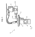
- the number 10 designates a fuel suction system for the tank of a motor vehicle, in particular of an agricultural tractor.
- the suction system 10 comprises a plenum chamber 12 provided with a lid 14.
- the suction system 10 comprises a suction pump 16 connected to the plenum chamber 12 by two or more suction conduits 18, 19 arranged in parallel with each other.
- Each suction conduit 18, 19 is provided with a respective electrically controlled valve 20, 22.
- the sensors 24, 26 are of the float type, each of which is able to provide an electrical signal which indicates whether the level of the fuel inside the plenum chamber 12 is higher or lower than a predetermined threshold.
- the sensors 24, 26 are preferably of the ON/OFF type, i.e. capable of indicating only whether the fuel level is above or below the reference threshold.
- the level sensors 24, 26 are connected to the respective electrically actuated valves 20, 22. Each level sensor 24, 26 provides an electrical signal which commands the closure of the respective valve 20, 22 when the sensed fuel level drops below the predetermined reference threshold.
- Figure 2 schematically shows the system according to the invention applied to a motor vehicle comprising a tank 28 and an internal combustion engine 20.
- the assemblies designated by the reference numbers 20, 24 and 22, 26 indicate level sensor/electrical valve set.
- the electrical valves can be mounted directly on the level sensor with the two distinct components, or a single body could be provided with electrical valve incorporated in the float.
- the electrical valves can be of the normally opened or normally closed type.
- the system shown schematically in Figure 2 comprises a fuel filter 30 and a pre-filter 32 arranged in series upstream of the suction pump 16.
- one of the two floats for example the float 26, no longer senses the presence of fuel so it commands the closure of the respective electrical valve 22.
- the floats are preferably calibrated in such a way as to command the closure of the respective electrical valve when the related suction conduit is still full of fuel. In this way, the suction of air into the conduit is prevented.
- the system according to the invention allows the suction of fuel even in the conditions of travel in which a traditional suction system would have problems.
- the system according to the invention allows to increase the range of the vehicle and to minimise the unused volume of the tank. Consequently, the designer is free to devise tanks with the most extreme shapes without worrying about compromising the suction of the tank. Moreover, under any operating condition of the vehicle the circulation of air in the fuel suction system is prevented.
Priority Applications (1)
| Application Number | Priority Date | Filing Date | Title |
|---|---|---|---|
| EP04425108A EP1566304A1 (de) | 2004-02-23 | 2004-02-23 | Kraftstoffversorgungssystem für ein Motorfahrzeug |
Applications Claiming Priority (1)
| Application Number | Priority Date | Filing Date | Title |
|---|---|---|---|
| EP04425108A EP1566304A1 (de) | 2004-02-23 | 2004-02-23 | Kraftstoffversorgungssystem für ein Motorfahrzeug |
Publications (1)
| Publication Number | Publication Date |
|---|---|
| EP1566304A1 true EP1566304A1 (de) | 2005-08-24 |
Family
ID=34707429
Family Applications (1)
| Application Number | Title | Priority Date | Filing Date |
|---|---|---|---|
| EP04425108A Withdrawn EP1566304A1 (de) | 2004-02-23 | 2004-02-23 | Kraftstoffversorgungssystem für ein Motorfahrzeug |
Country Status (1)
| Country | Link |
|---|---|
| EP (1) | EP1566304A1 (de) |
Citations (5)
| Publication number | Priority date | Publication date | Assignee | Title |
|---|---|---|---|---|
| DE3144581A1 (de) * | 1981-11-10 | 1983-05-26 | SWF-Spezialfabrik für Autozubehör Gustav Rau GmbH, 7120 Bietigheim-Bissingen | Fuellstandsgeber zur messung des tankinhalts bei kraftfahrzeugen |
| DE19833932A1 (de) * | 1998-07-28 | 1999-10-28 | Siemens Ag | Kraftstoffversorgungssystem für eine Brennkraftmaschine |
| JP2001012326A (ja) * | 1999-06-29 | 2001-01-16 | Kubota Corp | 作業機用エンジンの燃料供給装置 |
| DE20113898U1 (de) * | 2001-08-22 | 2001-12-06 | Herma Train Components Gmbh | Flüssigkeitsbehälter für Fahrzeuge |
| US6588449B1 (en) * | 2000-08-31 | 2003-07-08 | Saturn Electronics & Engineering, Inc. | Diesel fuel shut-off device |
-
2004
- 2004-02-23 EP EP04425108A patent/EP1566304A1/de not_active Withdrawn
Patent Citations (5)
| Publication number | Priority date | Publication date | Assignee | Title |
|---|---|---|---|---|
| DE3144581A1 (de) * | 1981-11-10 | 1983-05-26 | SWF-Spezialfabrik für Autozubehör Gustav Rau GmbH, 7120 Bietigheim-Bissingen | Fuellstandsgeber zur messung des tankinhalts bei kraftfahrzeugen |
| DE19833932A1 (de) * | 1998-07-28 | 1999-10-28 | Siemens Ag | Kraftstoffversorgungssystem für eine Brennkraftmaschine |
| JP2001012326A (ja) * | 1999-06-29 | 2001-01-16 | Kubota Corp | 作業機用エンジンの燃料供給装置 |
| US6588449B1 (en) * | 2000-08-31 | 2003-07-08 | Saturn Electronics & Engineering, Inc. | Diesel fuel shut-off device |
| DE20113898U1 (de) * | 2001-08-22 | 2001-12-06 | Herma Train Components Gmbh | Flüssigkeitsbehälter für Fahrzeuge |
Non-Patent Citations (1)
| Title |
|---|
| PATENT ABSTRACTS OF JAPAN vol. 2000, no. 16 8 May 2001 (2001-05-08) * |
Similar Documents
| Publication | Publication Date | Title |
|---|---|---|
| US20020088439A1 (en) | Fuel tank | |
| US5868119A (en) | Fuel tank venting system for vehicles | |
| US9884555B2 (en) | Vehicle control system | |
| JP5838162B2 (ja) | 自動車の燃料タンク | |
| US5456238A (en) | Evaporative fuel processing device | |
| US7455042B2 (en) | Suction system with a device for avoiding the ingress of water | |
| CN101469648B (zh) | 炭罐结构 | |
| EP1055541A3 (de) | Elektromechanisch gesteuertes Betankungsventil | |
| US6425379B2 (en) | Evaporative emission control system | |
| US5427076A (en) | Evaporative fuel-processing system for internal combustion engines for vehicles | |
| US20210370762A1 (en) | Electronic fuel tank system having cam actuated venting with canister line isolation | |
| CN104470748A (zh) | 用于鞍形燃料储箱的通气的方法和阀门 | |
| US7970528B2 (en) | Gaseous fuel management system for automotive vehicle | |
| CN101118172B (zh) | 空燃油水平检测的交互校验 | |
| SE9402304L (sv) | Förfarande för tankavluftning | |
| US5803054A (en) | Evaporative fuel-processing system for internal combustion engines for vehicles | |
| US5918282A (en) | Fuel tank pressure sensor assembly with integral rollover protection | |
| EP1566304A1 (de) | Kraftstoffversorgungssystem für ein Motorfahrzeug | |
| JP2009068350A (ja) | 大気導入部の構造 | |
| EP2234834B1 (de) | Kraftstofftanksystem | |
| US5918581A (en) | Evaporative emission control system for internal combustion engines | |
| CA1280980C (en) | Fuel tank for an off-road vehicle | |
| US20120138169A1 (en) | Fuel tank vaporization gas purge system | |
| JPS63170120A (ja) | エンジンと無関係の車両暖房装置の燃料供給装置 | |
| CN106882036B (zh) | 用于车辆的燃料箱的翻转阀 |
Legal Events
| Date | Code | Title | Description |
|---|---|---|---|
| PUAI | Public reference made under article 153(3) epc to a published international application that has entered the european phase |
Free format text: ORIGINAL CODE: 0009012 |
|
| AK | Designated contracting states |
Kind code of ref document: A1 Designated state(s): AT BE BG CH CY CZ DE DK EE ES FI FR GB GR HU IE IT LI LU MC NL PT RO SE SI SK TR |
|
| AX | Request for extension of the european patent |
Extension state: AL LT LV MK |
|
| 17P | Request for examination filed |
Effective date: 20050713 |
|
| AKX | Designation fees paid |
Designated state(s): DE ES FR GB IT PT |
|
| 17Q | First examination report despatched |
Effective date: 20060908 |
|
| STAA | Information on the status of an ep patent application or granted ep patent |
Free format text: STATUS: THE APPLICATION IS DEEMED TO BE WITHDRAWN |
|
| 18D | Application deemed to be withdrawn |
Effective date: 20060228 |