EP1566231B1 - Powder press - Google Patents
Powder press Download PDFInfo
- Publication number
- EP1566231B1 EP1566231B1 EP05001884A EP05001884A EP1566231B1 EP 1566231 B1 EP1566231 B1 EP 1566231B1 EP 05001884 A EP05001884 A EP 05001884A EP 05001884 A EP05001884 A EP 05001884A EP 1566231 B1 EP1566231 B1 EP 1566231B1
- Authority
- EP
- European Patent Office
- Prior art keywords
- rams
- powder
- press
- hydraulic cylinder
- die
- Prior art date
- Legal status (The legal status is an assumption and is not a legal conclusion. Google has not performed a legal analysis and makes no representation as to the accuracy of the status listed.)
- Expired - Lifetime
Links
- 239000000843 powder Substances 0.000 title claims abstract description 19
- 238000003825 pressing Methods 0.000 claims description 19
- 238000004519 manufacturing process Methods 0.000 claims description 7
- 239000000463 material Substances 0.000 claims description 6
- 239000002184 metal Substances 0.000 abstract description 3
- 229910052751 metal Inorganic materials 0.000 abstract description 3
- 239000011159 matrix material Substances 0.000 abstract 2
- 238000000034 method Methods 0.000 description 8
- 238000010586 diagram Methods 0.000 description 7
- 230000006835 compression Effects 0.000 description 6
- 238000007906 compression Methods 0.000 description 6
- 239000012778 molding material Substances 0.000 description 2
- 238000005245 sintering Methods 0.000 description 2
- 238000013459 approach Methods 0.000 description 1
- 239000000919 ceramic Substances 0.000 description 1
- 238000012937 correction Methods 0.000 description 1
- 230000003247 decreasing effect Effects 0.000 description 1
- 239000008187 granular material Substances 0.000 description 1
- 238000005259 measurement Methods 0.000 description 1
- 150000002739 metals Chemical class 0.000 description 1
- 238000000465 moulding Methods 0.000 description 1
- 239000008188 pellet Substances 0.000 description 1
- 230000001105 regulatory effect Effects 0.000 description 1
- 238000005070 sampling Methods 0.000 description 1
- 239000007858 starting material Substances 0.000 description 1
- 238000012360 testing method Methods 0.000 description 1
Images

Classifications
-
- B—PERFORMING OPERATIONS; TRANSPORTING
- B22—CASTING; POWDER METALLURGY
- B22F—WORKING METALLIC POWDER; MANUFACTURE OF ARTICLES FROM METALLIC POWDER; MAKING METALLIC POWDER; APPARATUS OR DEVICES SPECIALLY ADAPTED FOR METALLIC POWDER
- B22F3/00—Manufacture of workpieces or articles from metallic powder characterised by the manner of compacting or sintering; Apparatus specially adapted therefor ; Presses and furnaces
- B22F3/02—Compacting only
- B22F3/03—Press-moulding apparatus therefor
-
- B—PERFORMING OPERATIONS; TRANSPORTING
- B30—PRESSES
- B30B—PRESSES IN GENERAL
- B30B11/00—Presses specially adapted for forming shaped articles from material in particulate or plastic state, e.g. briquetting presses, tabletting presses
- B30B11/005—Control arrangements
-
- B—PERFORMING OPERATIONS; TRANSPORTING
- B30—PRESSES
- B30B—PRESSES IN GENERAL
- B30B11/00—Presses specially adapted for forming shaped articles from material in particulate or plastic state, e.g. briquetting presses, tabletting presses
- B30B11/02—Presses specially adapted for forming shaped articles from material in particulate or plastic state, e.g. briquetting presses, tabletting presses using a ram exerting pressure on the material in a moulding space
-
- B—PERFORMING OPERATIONS; TRANSPORTING
- B30—PRESSES
- B30B—PRESSES IN GENERAL
- B30B15/00—Details of, or accessories for, presses; Auxiliary measures in connection with pressing
- B30B15/0094—Press load monitoring means
-
- B—PERFORMING OPERATIONS; TRANSPORTING
- B30—PRESSES
- B30B—PRESSES IN GENERAL
- B30B15/00—Details of, or accessories for, presses; Auxiliary measures in connection with pressing
- B30B15/06—Platens or press rams
- B30B15/065—Press rams
- B30B15/067—Press rams with means for equalizing the pressure exerted by a plurality of press rams
-
- B—PERFORMING OPERATIONS; TRANSPORTING
- B22—CASTING; POWDER METALLURGY
- B22F—WORKING METALLIC POWDER; MANUFACTURE OF ARTICLES FROM METALLIC POWDER; MAKING METALLIC POWDER; APPARATUS OR DEVICES SPECIALLY ADAPTED FOR METALLIC POWDER
- B22F3/00—Manufacture of workpieces or articles from metallic powder characterised by the manner of compacting or sintering; Apparatus specially adapted therefor ; Presses and furnaces
- B22F3/02—Compacting only
- B22F3/03—Press-moulding apparatus therefor
- B22F2003/033—Press-moulding apparatus therefor with multiple punches working in the same direction
-
- B—PERFORMING OPERATIONS; TRANSPORTING
- B22—CASTING; POWDER METALLURGY
- B22F—WORKING METALLIC POWDER; MANUFACTURE OF ARTICLES FROM METALLIC POWDER; MAKING METALLIC POWDER; APPARATUS OR DEVICES SPECIALLY ADAPTED FOR METALLIC POWDER
- B22F2999/00—Aspects linked to processes or compositions used in powder metallurgy
Definitions
- the invention relates to a powder press for the production of compacts of powdered molding material according to the claim.
- a press has an upper and a lower punch, which interact with a die or a die bore in a die plate.
- the punches are driven by a suitable power drive, either mechanically or hydraulically via suitable hydraulic cylinders. It is known to arrange the die plate firmly and to move upper and lower punches or alternatively to move the die plate and to adjust the upper punch, while the lower punch remains stationary.
- Hydraulic presses have the advantage that a relatively freely programmable pressing process can be achieved.
- Out DE 4 209 767 C1 It is known to measure the pressing force in order to achieve the most uniform possible density within a batch. Depending on the measured pressing force is then a Correction made over the filling for the subsequent compacts.
- the position of the stamp is determined and measured the associated pressing force. The approach of a certain position leads to a relatively high dimensional accuracy, may cause different densities. If, however, the pressing process is terminated at a preset pressing force, there is a risk that the compact has different thicknesses.
- the aim of all procedures is to ensure, with the aid of suitable control measures, that the same pressing result is always achieved even with changing powder within a batch.
- a production cycle consists of several phases: filling of the material, collapse of the punches, compacting of the pressing material, press holding time, extension of the compact and its removal.
- the removal is usually carried out by an automatic removal system.
- To increase the output of the press an attempt is made to shorten the times of the individual phases.
- the times for compacting the powder, the press holding time and the time for extending the compact depend on the type of powder used and the geometry of the compact. Too short compression, Presshalte- and ejection times lead to hairline cracks in the compact, which must be avoided at all costs. For this reason, the output of modern hydraulic powder presses is currently limited to max. 30 pieces per minute limited.
- the invention has for its object to provide a powder press for the production of compacts of powdered molding material with which the ejection performance can be significantly increased without a loss of press accuracy must be accepted.
- a fixed or movable die plate is provided with at least two dies or a die with at least two die holes.
- at least two upper punches are furthermore provided, which interact with the dies or die bores and act individually or are mechanically coupled. They are operated by two or a single hydraulic cylinder.
- at least two lower punches are provided which cooperate with the dies or die bores and each have their own drive by means of a hydraulic cylinder.
- the upper stamps are assigned one or two position sensors and the lower stamps each have one or two position sensors.
- the hydraulic cylinders are assigned a force sensor.
- a process computer for the powder press according to the invention on at least three controllers, namely a controller for the hydraulic cylinder of the upper or lower punch and in each case a controller for the hydraulic cylinder of the lower or upper punch.
- the algorithm by which the individual controllers operate can be formulated in a conventional manner. So z. As a rule after a Kraftweg- or a power timing diagram or even after the energy input possible. In all regulations, the target diagram must first be determined with the aid of suitable tests and measurements, which are then regu- lated during the actual production.
- the powder press according to the invention With the help of the powder press according to the invention, two or more compacts can be produced simultaneously, whereby the Prcssvorêt be influenced separately for the individual compacts, whereby z. B. Powder fluctuations and tool tolerances be compensated.
- the powder press according to the invention thus enables a large pressing accuracy by separately influencing the pressing operations.
- the removal of the finished compacts by the sampling system can be done in one or more steps, the removal is preferable in one step because of the shorter cycle time. Due to the simultaneous pressing and removal of several compacts, the ejection capacity of the press is multiplied according to the number of simultaneously pressed compacts, without the pressing accuracy suffers.
- a press for pressing powdered press material is shown schematically. It has a fixed die plate 10, which contains two dies 12, 14, each with a die bore. Above the die plate 10, two upper punches 16 are arranged, which cooperate with the dies 12, 14. The upper punches 16 are mechanically coupled to each other by a block 18. The block 18 is actuated by a hydraulic cylinder 20.
- Two lower punches 22 cooperate with the dies 12, 14 and are each actuated by a hydraulic cylinder 24 and 26, respectively.
- the upper stamp 16 is a Assigned to the position sensor 28 and the hydraulic cylinder 20, a force sensor 30 is assigned.
- the actuation of the hydraulic cylinder and the upper punch 16 takes place with the aid of a controller 32 in accordance with the values of force sensor 30 and position sensor 28 according to a predetermined algorithm, for example a force path or force time diagram.
- a controller 32 As an actuator serves a control valve 34 for the hydraulic cylinder 20th
- the lower punches 22 each have their own position sensors 36 and 38, respectively, and the force applied by the hydraulic cylinders 24, 26 is determined with separate force sensors 40 and 42, respectively.
- the algorithm for the controllers 44, 46 corresponds to z. B. after which the controller 32 operates.
- the manipulated variables of the regulators 44 and 46 are applied to the hydraulic cylinders 24, 26 via control valves 48 and 50, respectively.
- a hydraulic drive assembly 50 has two concentrically arranged annular piston 52, 56 which are guided in corresponding annular cylinders.
- annular piston 52, 56 which are guided in corresponding annular cylinders.
- each ring piston can be detected separately in its position and in view of the pressing forces.
Landscapes
- Engineering & Computer Science (AREA)
- Mechanical Engineering (AREA)
- Manufacturing & Machinery (AREA)
- Control Of Presses (AREA)
- Powder Metallurgy (AREA)
- Press Drives And Press Lines (AREA)
- Manufacturing Of Micro-Capsules (AREA)
- Glass Compositions (AREA)
Abstract
Description
Die Erfindung bezieht sich auf eine Pulverpresse zur Herstellung von Presslingen aus pulverförmigem Pressmaterial nach dem Patentanspruch.The invention relates to a powder press for the production of compacts of powdered molding material according to the claim.
Es ist bekannt, Formteile aus Hartmetall, Keramik, Sintermetallen oder dergleichen mit Hilfe von Pressen herzustellen. Das pulverförmige bzw. granuläre Material wird mit Hilfe von Pressen zu einem Formling geformt, der anschließend einem Sinterprozeß unterworfen wird. Eine Presse weist einen Ober- und einen Unterstempel auf, die mit einer Matrize bzw. einer Matrizenbohrung in einer Matrizenplatte zusammenwirken. Die Stempel werden von einem geeigneten Kraftantrieb angetrieben, entweder mechanisch oder hydraulisch über geeignete Hydraulikzylinder. Es ist bekannt, die Matrizenplatte fest anzuordnen und Ober- und Unterstempel zu bewegen oder alternativ die Matrizenplatte zu verfahren und den Oberstempel zu verstellen, während der Unterstempel stationär bleibt.It is known to produce molded parts made of hard metal, ceramic, sintered metals or the like by means of presses. The powdery or granular material is formed by means of pressing to a molding, which is then subjected to a sintering process. A press has an upper and a lower punch, which interact with a die or a die bore in a die plate. The punches are driven by a suitable power drive, either mechanically or hydraulically via suitable hydraulic cylinders. It is known to arrange the die plate firmly and to move upper and lower punches or alternatively to move the die plate and to adjust the upper punch, while the lower punch remains stationary.
Wesentlich für die reproduzierbare Herstellung von Pulverpresslingen ist, dass der Pressling eine homogene Struktur erhält bei einer vorgegebenen Dichte. Presslinge mit geringer Dichte schwinden beim Sintern schneller als Presslinge mit höherer Dichte. Durch unterschiedlich einstellbare Presswege von Unter- und Oberstempel kann versucht werden, Dichteabweichungen zu minimieren. Andererseits können unterschiedliche Dichten in der Praxis durch unterschiedliche Presskräfte entstehen, die wiederum bei gleicher Höhe der Presslinge, z. B. aufgrund von Füllschwankungen, die bis zu einigen Prozenten gehen, hervorgerufen werden.Essential for the reproducible production of powder compacts is that the compact obtains a homogeneous structure at a given density. Low density compacts shrink faster during sintering than higher density compacts. By differently adjustable pressing paths of lower and upper punch can be tried to minimize density deviations. On the other hand, different densities can arise in practice by different pressing forces, which in turn at the same height of the compacts, z. B. due to Füllschwankungen that go up to a few percent, caused.
Hydraulische Pressen haben den Vorteil, dass ein relativ frei programmierbarer Pressablauf erzielt werden kann. Aus
Aus
Aus
Ziel aller Verfahren ist, mit Hilfe geeigneter Regelungsvorkehrungen sicherzustellen, dass auch bei sich veränderndem Pulver innerhalb einer Charge immer ein gleiches Pressergebnis erzielt wird.The aim of all procedures is to ensure, with the aid of suitable control measures, that the same pressing result is always achieved even with changing powder within a batch.
Ein Produktionszyklus besteht aus mehreren Phasen: Füllen des Materials, Zusammenfahren der Stempel, Verdichten des Pressmaterials, Presshaltezeit, Ausfahren des Presslings und seine Entnahme. Die Entnahme erfolgt normalerweise durch ein automatisches Entnahmesystem. Um die Ausstossleistung der Presse zu erhöhen, wird versucht, die Zeiten der einzelnen Phasen zu verkürzen. In dieser Hinsicht bestehen verfahrenstechnische Grenzen, die einer Zykluszeitverringerung entgegenstehen. Die Zeiten für das Verdichten des Pulvers, die Presshaltezeit und die Zeit zum Ausfahren des Presslings ist abhängig von der Art des eingesetzten Pulvers und der Geometrie des Presslings. Zu kurze Verdichtungs-, Presshalte- und Ausstosszeiten führen zu Haarrissen im Pressling, was unbedingt vermieden werden muss. Aus diesem Grund ist die Ausstossleistung moderner hydraulischer Pulverpressen derzeit auf max. 30 Stück pro Minute begrenzt.A production cycle consists of several phases: filling of the material, collapse of the punches, compacting of the pressing material, press holding time, extension of the compact and its removal. The removal is usually carried out by an automatic removal system. To increase the output of the press, an attempt is made to shorten the times of the individual phases. In this regard, there are procedural limitations that preclude cycle time reduction. The times for compacting the powder, the press holding time and the time for extending the compact depend on the type of powder used and the geometry of the compact. Too short compression, Presshalte- and ejection times lead to hairline cracks in the compact, which must be avoided at all costs. For this reason, the output of modern hydraulic powder presses is currently limited to max. 30 pieces per minute limited.
Der Erfindung liegt die Aufgabe zugrunde, eine Pulverpresse zur Herstellung von Presslingen aus pulverförmigem Pressmaterial zu schaffen, mit der die Ausstossleistung deutlich gesteigert werden kann, ohne dass eine Einbuße an Pressgenauigkeit hingenommen werden muß.The invention has for its object to provide a powder press for the production of compacts of powdered molding material with which the ejection performance can be significantly increased without a loss of press accuracy must be accepted.
Diese Aufgabe wird durch die Merkmale des Patentanspruchs 1 gelöst.This object is solved by the features of patent claim 1.
Bei der erfindungsgemäßen Pulverpresse ist eine feststehende oder bewegliche Matrizenplatte vorgesehen mit mindestens zwei Matrizen oder einer Matrize mit mindestens zwei Matrizenbohrungen. Bei der erfindungsgemäßen Pulverpresse sind ferner mindestens zwei Oberstempel vorgesehen, die mit den Matrizen bzw. Matrizenbohrungen zusammenwirken und einzeln wirken oder mechanisch gekoppelt sind. Sie werden von zwei bzw. einem einzigen hydraulischen Zylinder betätigt. Ferner sind mindestens zwei Unterstempel vorgesehen, die mit den Matrizen bzw. Matrizenbohrungen zusammenwirken und jeweils einen eigenen Antrieb mittels eines Hydraulikzylinders aufweisen. Den Oberstempeln sind ein oder zwei Positionssensoren und den Unterstempeln jeweils ein oder zwei Positionssensoren zugeordnet. Den Hydraulikzylindern ist ein Kraftsensor zugeordnet. Schließlich weist ein Prozessrechner für die erfindungsgemäße Pulverpresse mindestens drei Regler auf, nämlich einen Regler für den Hydraulikzylinder der Ober- oder Unterstempel und jeweils einen Regler für die Hydraulikzylinder der Unter- oder Oberstempel.In the powder press according to the invention a fixed or movable die plate is provided with at least two dies or a die with at least two die holes. In the case of the powder press according to the invention, at least two upper punches are furthermore provided, which interact with the dies or die bores and act individually or are mechanically coupled. They are operated by two or a single hydraulic cylinder. Furthermore, at least two lower punches are provided which cooperate with the dies or die bores and each have their own drive by means of a hydraulic cylinder. The upper stamps are assigned one or two position sensors and the lower stamps each have one or two position sensors. The hydraulic cylinders are assigned a force sensor. Finally, a process computer for the powder press according to the invention on at least three controllers, namely a controller for the hydraulic cylinder of the upper or lower punch and in each case a controller for the hydraulic cylinder of the lower or upper punch.
Der Algorithmus, nach dem die einzelnen Regler arbeiten, kann in herkömmlicher Weise formuliert sein. So ist z. B. eine Regelung nach einem Kraftweg- oder einem Kraftzeitdiagramm oder auch nach dem Energieeintrag möglich. Bei allen Regelungen ist zuvor mit Hilfe geeigneter Versuche und Messungen das Solldiagramm zu ermitteln, denen während der eigentlichen Produktion regelnd nachgefahren wird.The algorithm by which the individual controllers operate can be formulated in a conventional manner. So z. As a rule after a Kraftweg- or a power timing diagram or even after the energy input possible. In all regulations, the target diagram must first be determined with the aid of suitable tests and measurements, which are then regu- lated during the actual production.
Mit Hilfe der erfindungsgemäßen Pulverpresse können zwei oder mehr Presslinge gleichzeitig erzeugt werden, wobei die Prcssvorgänge für die einzelnen Presslinge getrennt beeinflusst werden, wodurch z. B. Pulverschwankungen und Werkzeug-toleranzen ausgeglichen werden. Die erfindungsgemäße Pulverpresse ermöglicht somit eine große Pressgenauigkeit durch getrennte Beeinflussung der Pressvorgänge.With the help of the powder press according to the invention, two or more compacts can be produced simultaneously, whereby the Prcssvorgänge be influenced separately for the individual compacts, whereby z. B. Powder fluctuations and tool tolerances be compensated. The powder press according to the invention thus enables a large pressing accuracy by separately influencing the pressing operations.
Die Entnahme der gefertigten Presslinge durch das Entnahmesystem kann in einem oder mehreren Arbeitsschritten erfolgen, wobei die Entnahme in einem Arbeitsschritt wegen der kürzeren Zykluszeit vorzuziehen ist. Durch das gleichzeitige Pressen und Entnehmen mehrerer Presslinge wird die Ausstossleistung der Presse nach Maßgabe der Anzahl gleichzeitig gepresster Presslinge vervielfacht, ohne dass die Pressgenauigkeit darunter leidet.The removal of the finished compacts by the sampling system can be done in one or more steps, the removal is preferable in one step because of the shorter cycle time. Due to the simultaneous pressing and removal of several compacts, the ejection capacity of the press is multiplied according to the number of simultaneously pressed compacts, without the pressing accuracy suffers.
Ausführungsbeispiele der Erfindung werden nachfolgend anhand einer Zeichnung näher erläutert.
- Figur 1
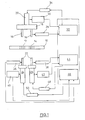
- zeigt ein Blockschaltbild einer ersten Ausführungsform einer Presse nach der Erfindung,
- Figur 2
- zeigt ein Blockschaltbild einer zweiten Ausführungsform einer Presse nach der Erfindung.
- FIG. 1
- shows a block diagram of a first embodiment of a press according to the invention,
- FIG. 2
- shows a block diagram of a second embodiment of a press according to the invention.
In der Figur ist eine Presse zum Pressen von pulverförmigem Pressmaterial schematisch dargestellt. Sie weist eine feststehende Matrizenplatte 10 auf, die zwei Matrizen 12, 14 enthält mit jeweils einer Matrizenbohrung. Oberhalb der Matrizenplatte 10 sind zwei Oberstempel 16 angeordnet, die mit den Matrizen 12, 14 zusammenwirken. Die Oberstempel 16 sind durch einen Block 18 mechanisch miteinander gekoppelt. Der Block 18 wird von einem Hydraulikzylinder 20 betätigt.In the figure, a press for pressing powdered press material is shown schematically. It has a
Zwei Unterstempel 22 wirken mit den Matrizen 12, 14 zusammen und sind jeweils von einem Hydraulikzylinder 24 bzw. 26 betätigt. Den Oberstempeln 16 ist ein Positionssensor 28 zugeordnet und dem Hydraulikzylinder 20 ist ein Kraftsensor 30 zugeordnet. Die Betätigung des Hydraulikzylinders und der Oberstempel 16 erfolgt mit Hilfe eines Reglers 32 nach Maßgabe der Werte von Kraftsensor 30 und Positionssensor 28 nach einem vorgegebenen Algorithmus beispielsweise einem Kraftweg- oder Kraftzeitdiagramm. Als Stellglied dient ein Regelventil 34 für den Hydraulikzylinder 20.Two
Wie zu erkennen, ist den Unterstempeln 22 jeweils ein eigener Positionssensor 36 bzw. 38 zugeordnet und die von den Hydraulikzylindern 24, 26 aufgebrachte Kraft wird mit separaten Kraftsensoren 40 bzw. 42 ermittelt. Die Betätigung der Hydraulikzylinder 24, 26 erfolgt über getrennte Regler 44 bzw. 46 nach Maßgabe der Daten, die von den Positionssensoren 36, 38 bzw. Kraftsensoren 40, 42 geliefert werden. Der Algorithmus für die Regler 44, 46 entspricht z. B. dem nach dem der Regler 32 arbeitet. Die Stellgrößen der Regler 44 bzw. 46 werden über Regelventile 48 bzw. 50 auf die Hydraulikzylinder 24, 26 gegeben.As can be seen, the
Es ist zu erkennen, dass mit einem minimalen apparativen Aufwand eine hohe Ausstossleistung mit einer Presse erzielt wird, bei gleichzeitig hoher Pressgenauigkeit für jede Achse, da jede Achse getrennt geregelt wird.It can be seen that a high output with a press is achieved with minimal equipment expense, while high press accuracy for each axis, since each axis is controlled separately.
Soweit bei der Ausführungsform nach
Die Besonderheit bei
Es versteht sich, daß auch die Oberstempel 16 zusätzlich oder alternativ mit einer Ringzylinderanordnung angetrieben werden können, wobei jeder Ringkolben in seiner Position und im Hinblick auf die Preßkräfte separat detektiert werden kann.It is understood that the
Schließlich versteht sich, daß bei Pressen, bei denen eine angetriebene Matrizenplatte verwendet wird, während die Unterstempel stationär sind, die beschriebene Anordnung ebenfalls eingesetzt werden kann. In diesem Falle ist es zweckmäßig, die Oberstempel separat anzutreiben und ihren Betrieb separat zu regeln, während die Matrizenplatte durch einen oder mehrere Hydraulikzylinder verstellt wird.Finally, it is understood that in presses where a driven die plate is used while the lower dies are stationary, the described arrangement can also be used. In this case it is expedient to drive the upper punches separately and to regulate their operation separately, while the die plate is adjusted by one or more hydraulic cylinders.
Claims (3)
- A powder press for the production of pressed articles of powder-shaped pressing material, with the following features:• a die plate (10) with at least two dies (12, 14) or one die having at least two die bores,• at least two upper rams, which co-operate with the dies (12) or the die bores, respectively,• one or two hydraulic cylinders (20) for the upper rams (16),• at least two lower rams (22), which co-operate with the dies (14) or the die bores, respectively,• one hydraulic cylinder (24, 26) for each of the lower rams (22),• at least one position sensor for the upper rams (16) and at least one force sensor (30) for the one or plural hydraulic cylinder(s) (30) of the upper rams,at least one position sensor (28) for each of the lower rams (22) and at least one force sensor (40, 42) for each of the hydraulic cylinders (24, 26) of the lower rams,• a controller (32) for the one or plural hydraulic cylinder(s) (20) for the upper rams (16),• one controller (44, 46) for each of the hydraulic cylinders (24, 26) of the lower rams (22).
- A powder press according to claim 1, characterised in that the upper rams (16) or the lower rams (22) are mechanically coupled and connected to a hydraulic cylinder (20), and that one single position sensor (28) is provided for the upper rams (16).
- A powder press according to any one of claims 1 or 2, characterised in that in case of separate hydraulic cylinders for the lower rams, ring cylinders (50) with ring pistons (52, 56) are provided.
Applications Claiming Priority (2)
| Application Number | Priority Date | Filing Date | Title |
|---|---|---|---|
| DE102004008322A DE102004008322B4 (en) | 2004-02-20 | 2004-02-20 | powder Press |
| DE102004008322 | 2004-02-20 |
Publications (3)
| Publication Number | Publication Date |
|---|---|
| EP1566231A2 EP1566231A2 (en) | 2005-08-24 |
| EP1566231A3 EP1566231A3 (en) | 2007-01-03 |
| EP1566231B1 true EP1566231B1 (en) | 2010-09-08 |
Family
ID=34706867
Family Applications (1)
| Application Number | Title | Priority Date | Filing Date |
|---|---|---|---|
| EP05001884A Expired - Lifetime EP1566231B1 (en) | 2004-02-20 | 2005-01-29 | Powder press |
Country Status (4)
| Country | Link |
|---|---|
| US (1) | US7351048B2 (en) |
| EP (1) | EP1566231B1 (en) |
| AT (1) | ATE480351T1 (en) |
| DE (2) | DE102004008322B4 (en) |
Cited By (1)
| Publication number | Priority date | Publication date | Assignee | Title |
|---|---|---|---|---|
| DE102015101586A1 (en) | 2015-02-04 | 2016-08-04 | Fette Compacting Gmbh | Powder press for the production of compacts from powdered pressed material |
Families Citing this family (11)
| Publication number | Priority date | Publication date | Assignee | Title |
|---|---|---|---|---|
| TR200807386T2 (en) * | 2006-02-22 | 2008-11-21 | Hydraform Developments (Proprietary) Limited | Automatic Block Manufacturing Machine |
| DE102006020213B4 (en) * | 2006-05-02 | 2009-09-10 | Fette Gmbh | Press for producing compacts of powder material |
| DE102008035301B3 (en) * | 2008-07-29 | 2010-03-25 | Fette Gmbh | powder Press |
| DE102009004620A1 (en) * | 2009-01-15 | 2010-07-22 | Gkn Sinter Metals Holding Gmbh | Method for operating a pressing device for the production of compacts of constant height from pulverulent materials, control device for such a pressing device and pressing device |
| US9314842B2 (en) * | 2011-12-02 | 2016-04-19 | Wildcat Discovery Technologies, Inc. | Hot pressing apparatus and method for same |
| DE102012019312A1 (en) * | 2012-10-01 | 2014-04-03 | Dorst Technologies Gmbh & Co. Kg | Method for controlling a ceramic and / or metal powder press or ceramic and / or metal powder press |
| DE102014105172B4 (en) * | 2014-04-11 | 2023-06-15 | Vacuumschmelze Gmbh & Co. Kg | PROCESS FOR THE SIMULTANEOUS MANUFACTURE OF AT LEAST TWO PERMANENT MAGNETS |
| JP6308195B2 (en) * | 2015-10-06 | 2018-04-11 | トヨタ自動車株式会社 | Method for controlling powder molding apparatus |
| CN109822964A (en) * | 2019-03-08 | 2019-05-31 | 萍乡鹏华液压机械制造有限公司 | Automatic tungsten carbide, titanium carbide powder hydraulic press |
| CN110385882B (en) * | 2019-06-17 | 2021-07-23 | 国网湖南省电力有限公司 | Zinc oxide powder press forming device |
| USD1032674S1 (en) * | 2022-12-21 | 2024-06-25 | Zhuobin Zhou | Powder press |
Family Cites Families (14)
| Publication number | Priority date | Publication date | Assignee | Title |
|---|---|---|---|---|
| DE1759429C3 (en) * | 1968-04-30 | 1973-12-20 | Villeroy & Boch Keramische Werke Kg, 6642 Mettlach | Device for pressing several plate-shaped pellets at the same time |
| US3890413A (en) * | 1974-08-15 | 1975-06-17 | Hydramet American Inc | Apparatus and method for compacting particulate materials |
| US4184827A (en) * | 1975-12-16 | 1980-01-22 | General Electric Company | Apparatus for monitoring and controlling the operation of a dual platen press |
| DE3939956A1 (en) * | 1989-12-02 | 1991-06-06 | Fette Wilhelm Gmbh | METHOD AND DEVICE FOR MONITORING THE PRESSING FORCE OF A TABLETING MACHINE |
| DE4209767C1 (en) * | 1992-03-23 | 1993-05-06 | Mannesmann Ag, 4000 Duesseldorf, De | |
| JPH08155694A (en) * | 1994-11-30 | 1996-06-18 | Yoshitsuka Seiki:Kk | Method for ensuring position of die in powder molding press |
| DE19717217C2 (en) * | 1997-04-24 | 1999-12-02 | Fette Wilhelm Gmbh | Method and device for producing compacts from hard metal, ceramic, sintered metal or the like |
| JP4144072B2 (en) * | 1998-07-09 | 2008-09-03 | 日立金属株式会社 | Magnetic powder molding apparatus and magnetic powder molding method |
| JP2975346B1 (en) * | 1998-07-29 | 1999-11-10 | 株式会社菊水製作所 | Powder compression molding machine |
| US6531090B2 (en) * | 2000-02-17 | 2003-03-11 | Sumitomo Special Metals Co., Ltd. | Method for producing powder compact and method for manufacturing magnet |
| DE10010671C2 (en) * | 2000-03-04 | 2002-03-14 | Fette Wilhelm Gmbh | Process for producing pressed parts by pressing metal powder and then sintering the compact |
| AU2002219865A1 (en) * | 2000-11-14 | 2002-05-27 | Materials Innovation Inc. | Hydraulic modular manufacturing system |
| DE10142772C2 (en) * | 2001-08-31 | 2003-09-25 | Fette Wilhelm Gmbh | Process for the production of pressed parts in a powder press |
| US7150617B1 (en) * | 2003-11-17 | 2006-12-19 | The United States Of America As Represented By The Secretary Of The Navy | Multiple position press |
-
2004
- 2004-02-20 DE DE102004008322A patent/DE102004008322B4/en not_active Expired - Fee Related
-
2005
- 2005-01-29 AT AT05001884T patent/ATE480351T1/en active
- 2005-01-29 DE DE502005010195T patent/DE502005010195D1/en not_active Expired - Lifetime
- 2005-01-29 EP EP05001884A patent/EP1566231B1/en not_active Expired - Lifetime
- 2005-02-16 US US11/058,967 patent/US7351048B2/en not_active Expired - Fee Related
Cited By (3)
| Publication number | Priority date | Publication date | Assignee | Title |
|---|---|---|---|---|
| DE102015101586A1 (en) | 2015-02-04 | 2016-08-04 | Fette Compacting Gmbh | Powder press for the production of compacts from powdered pressed material |
| EP3053736A1 (en) | 2015-02-04 | 2016-08-10 | Fette Compacting GmbH | Powder press for producing moulded articles from powder pressing material |
| DE102015101586B4 (en) | 2015-02-04 | 2019-02-21 | Fette Compacting Gmbh | Powder press for the production of compacts from powdered pressed material |
Also Published As
| Publication number | Publication date |
|---|---|
| DE102004008322A1 (en) | 2005-09-08 |
| DE502005010195D1 (en) | 2010-10-21 |
| ATE480351T1 (en) | 2010-09-15 |
| EP1566231A3 (en) | 2007-01-03 |
| EP1566231A2 (en) | 2005-08-24 |
| DE102004008322B4 (en) | 2008-11-27 |
| US7351048B2 (en) | 2008-04-01 |
| US20050186300A1 (en) | 2005-08-25 |
Similar Documents
| Publication | Publication Date | Title |
|---|---|---|
| DE19717217C2 (en) | Method and device for producing compacts from hard metal, ceramic, sintered metal or the like | |
| EP2103423B1 (en) | Powder moulding press for producing a pressed product from metal powder | |
| DE19882375B4 (en) | Forging-lowering device and compression forging method | |
| EP1566231B1 (en) | Powder press | |
| EP1693182B1 (en) | Method and apparatus for the trial pressing of multi-layer tablets or coated tablets | |
| EP1852247A2 (en) | Press for manufacturing moulded parts from powdered material | |
| DE68910248T2 (en) | ELECTRIC POWDER CASTING DEVICE. | |
| EP1129802B2 (en) | Process for controlling the pressing force for metal powder compression | |
| DE19917421C1 (en) | Process for briquetting metal chips and briquetting press | |
| DE3751244T2 (en) | Rotary presses of metal powder. | |
| EP1287975B1 (en) | Process for producing molded parts in a powder press | |
| EP3053736A1 (en) | Powder press for producing moulded articles from powder pressing material | |
| EP1277564B1 (en) | Method of compacting powder materials | |
| WO2000020192A1 (en) | Press for producing shaped bodies | |
| EP0185951A1 (en) | Consolidating tool for compressing metal powders | |
| DE2805187C2 (en) | Drop forging press | |
| DE10256654B4 (en) | Tablet press | |
| EP1602473B1 (en) | Apparatus for preparing a powder compact | |
| DE3244171A1 (en) | METHOD AND DEVICE FOR DETECTING A FORCE APPLYING BETWEEN TWO MACHINE PARTS MOVABLE AGAINST TOGETHER | |
| EP0284903B1 (en) | Piston press | |
| EP1190181B1 (en) | Method for producing friction linings | |
| DE102004012858B4 (en) | Roller body manufacturing method for roller bearing, involves measuring weight or volume of raw blocks, and feeding blocks in to pressing tool, where blocks are shaped in tool in two stages and deformed by stamp that penetrates in to tool | |
| DE2915966A1 (en) | Compression force measuring device for hydraulic press - uses two symmetrically-spaced pressure capsules or expansion strips | |
| DE102005027032B4 (en) | Device for producing a molded part | |
| DE2435405C2 (en) | Fine blanking device usable on a multi-purpose press |
Legal Events
| Date | Code | Title | Description |
|---|---|---|---|
| PUAI | Public reference made under article 153(3) epc to a published international application that has entered the european phase |
Free format text: ORIGINAL CODE: 0009012 |
|
| AK | Designated contracting states |
Kind code of ref document: A2 Designated state(s): AT BE BG CH CY CZ DE DK EE ES FI FR GB GR HU IE IS IT LI LT LU MC NL PL PT RO SE SI SK TR |
|
| AX | Request for extension of the european patent |
Extension state: AL BA HR LV MK YU |
|
| PUAL | Search report despatched |
Free format text: ORIGINAL CODE: 0009013 |
|
| AK | Designated contracting states |
Kind code of ref document: A3 Designated state(s): AT BE BG CH CY CZ DE DK EE ES FI FR GB GR HU IE IS IT LI LT LU MC NL PL PT RO SE SI SK TR |
|
| AX | Request for extension of the european patent |
Extension state: AL BA HR LV MK YU |
|
| 17P | Request for examination filed |
Effective date: 20061215 |
|
| AKX | Designation fees paid |
Designated state(s): AT BE BG CH CY CZ DE DK EE ES FI FR GB GR HU IE IS IT LI LT LU MC NL PL PT RO SE SI SK TR |
|
| 17Q | First examination report despatched |
Effective date: 20091016 |
|
| GRAP | Despatch of communication of intention to grant a patent |
Free format text: ORIGINAL CODE: EPIDOSNIGR1 |
|
| GRAS | Grant fee paid |
Free format text: ORIGINAL CODE: EPIDOSNIGR3 |
|
| GRAA | (expected) grant |
Free format text: ORIGINAL CODE: 0009210 |
|
| AK | Designated contracting states |
Kind code of ref document: B1 Designated state(s): AT BE BG CH CY CZ DE DK EE ES FI FR GB GR HU IE IS IT LI LT LU MC NL PL PT RO SE SI SK TR |
|
| REG | Reference to a national code |
Ref country code: GB Ref legal event code: FG4D Free format text: NOT ENGLISH |
|
| REG | Reference to a national code |
Ref country code: CH Ref legal event code: EP Ref country code: CH Ref legal event code: NV Representative=s name: BOHEST AG |
|
| REG | Reference to a national code |
Ref country code: SE Ref legal event code: TRGR |
|
| REG | Reference to a national code |
Ref country code: IE Ref legal event code: FG4D Free format text: LANGUAGE OF EP DOCUMENT: GERMAN |
|
| REF | Corresponds to: |
Ref document number: 502005010195 Country of ref document: DE Date of ref document: 20101021 Kind code of ref document: P |
|
| REG | Reference to a national code |
Ref country code: NL Ref legal event code: VDEP Effective date: 20100908 |
|
| PG25 | Lapsed in a contracting state [announced via postgrant information from national office to epo] |
Ref country code: LT Free format text: LAPSE BECAUSE OF FAILURE TO SUBMIT A TRANSLATION OF THE DESCRIPTION OR TO PAY THE FEE WITHIN THE PRESCRIBED TIME-LIMIT Effective date: 20100908 Ref country code: FI Free format text: LAPSE BECAUSE OF FAILURE TO SUBMIT A TRANSLATION OF THE DESCRIPTION OR TO PAY THE FEE WITHIN THE PRESCRIBED TIME-LIMIT Effective date: 20100908 |
|
| LTIE | Lt: invalidation of european patent or patent extension |
Effective date: 20100908 |
|
| PG25 | Lapsed in a contracting state [announced via postgrant information from national office to epo] |
Ref country code: SI Free format text: LAPSE BECAUSE OF FAILURE TO SUBMIT A TRANSLATION OF THE DESCRIPTION OR TO PAY THE FEE WITHIN THE PRESCRIBED TIME-LIMIT Effective date: 20100908 Ref country code: CY Free format text: LAPSE BECAUSE OF FAILURE TO SUBMIT A TRANSLATION OF THE DESCRIPTION OR TO PAY THE FEE WITHIN THE PRESCRIBED TIME-LIMIT Effective date: 20100908 Ref country code: PL Free format text: LAPSE BECAUSE OF FAILURE TO SUBMIT A TRANSLATION OF THE DESCRIPTION OR TO PAY THE FEE WITHIN THE PRESCRIBED TIME-LIMIT Effective date: 20100908 |
|
| REG | Reference to a national code |
Ref country code: IE Ref legal event code: FD4D |
|
| PG25 | Lapsed in a contracting state [announced via postgrant information from national office to epo] |
Ref country code: GR Free format text: LAPSE BECAUSE OF FAILURE TO SUBMIT A TRANSLATION OF THE DESCRIPTION OR TO PAY THE FEE WITHIN THE PRESCRIBED TIME-LIMIT Effective date: 20101209 Ref country code: NL Free format text: LAPSE BECAUSE OF FAILURE TO SUBMIT A TRANSLATION OF THE DESCRIPTION OR TO PAY THE FEE WITHIN THE PRESCRIBED TIME-LIMIT Effective date: 20100908 |
|
| PG25 | Lapsed in a contracting state [announced via postgrant information from national office to epo] |
Ref country code: IE Free format text: LAPSE BECAUSE OF FAILURE TO SUBMIT A TRANSLATION OF THE DESCRIPTION OR TO PAY THE FEE WITHIN THE PRESCRIBED TIME-LIMIT Effective date: 20100908 |
|
| PG25 | Lapsed in a contracting state [announced via postgrant information from national office to epo] |
Ref country code: PT Free format text: LAPSE BECAUSE OF FAILURE TO SUBMIT A TRANSLATION OF THE DESCRIPTION OR TO PAY THE FEE WITHIN THE PRESCRIBED TIME-LIMIT Effective date: 20110110 Ref country code: CZ Free format text: LAPSE BECAUSE OF FAILURE TO SUBMIT A TRANSLATION OF THE DESCRIPTION OR TO PAY THE FEE WITHIN THE PRESCRIBED TIME-LIMIT Effective date: 20100908 Ref country code: RO Free format text: LAPSE BECAUSE OF FAILURE TO SUBMIT A TRANSLATION OF THE DESCRIPTION OR TO PAY THE FEE WITHIN THE PRESCRIBED TIME-LIMIT Effective date: 20100908 Ref country code: SK Free format text: LAPSE BECAUSE OF FAILURE TO SUBMIT A TRANSLATION OF THE DESCRIPTION OR TO PAY THE FEE WITHIN THE PRESCRIBED TIME-LIMIT Effective date: 20100908 Ref country code: IS Free format text: LAPSE BECAUSE OF FAILURE TO SUBMIT A TRANSLATION OF THE DESCRIPTION OR TO PAY THE FEE WITHIN THE PRESCRIBED TIME-LIMIT Effective date: 20110108 Ref country code: EE Free format text: LAPSE BECAUSE OF FAILURE TO SUBMIT A TRANSLATION OF THE DESCRIPTION OR TO PAY THE FEE WITHIN THE PRESCRIBED TIME-LIMIT Effective date: 20100908 |
|
| PG25 | Lapsed in a contracting state [announced via postgrant information from national office to epo] |
Ref country code: ES Free format text: LAPSE BECAUSE OF FAILURE TO SUBMIT A TRANSLATION OF THE DESCRIPTION OR TO PAY THE FEE WITHIN THE PRESCRIBED TIME-LIMIT Effective date: 20101219 |
|
| PLBE | No opposition filed within time limit |
Free format text: ORIGINAL CODE: 0009261 |
|
| STAA | Information on the status of an ep patent application or granted ep patent |
Free format text: STATUS: NO OPPOSITION FILED WITHIN TIME LIMIT |
|
| BERE | Be: lapsed |
Owner name: FETTE G.M.B.H. Effective date: 20110131 |
|
| REG | Reference to a national code |
Ref country code: DE Ref legal event code: R081 Ref document number: 502005010195 Country of ref document: DE Owner name: FETTE COMPACTING GMBH, DE Free format text: FORMER OWNER: FETTE GMBH, 21493 SCHWARZENBEK, DE Effective date: 20110621 Ref country code: DE Ref legal event code: R082 Ref document number: 502005010195 Country of ref document: DE Representative=s name: HAUCK PATENT- UND RECHTSANWAELTE, DE Effective date: 20110621 Ref country code: DE Ref legal event code: R082 Ref document number: 502005010195 Country of ref document: DE Representative=s name: HAUCK PATENTANWALTSPARTNERSCHAFT MBB, DE Effective date: 20110621 |
|
| 26N | No opposition filed |
Effective date: 20110609 |
|
| PG25 | Lapsed in a contracting state [announced via postgrant information from national office to epo] |
Ref country code: DK Free format text: LAPSE BECAUSE OF FAILURE TO SUBMIT A TRANSLATION OF THE DESCRIPTION OR TO PAY THE FEE WITHIN THE PRESCRIBED TIME-LIMIT Effective date: 20100908 Ref country code: MC Free format text: LAPSE BECAUSE OF NON-PAYMENT OF DUE FEES Effective date: 20110131 |
|
| REG | Reference to a national code |
Ref country code: DE Ref legal event code: R097 Ref document number: 502005010195 Country of ref document: DE Effective date: 20110609 |
|
| PG25 | Lapsed in a contracting state [announced via postgrant information from national office to epo] |
Ref country code: BE Free format text: LAPSE BECAUSE OF NON-PAYMENT OF DUE FEES Effective date: 20110131 |
|
| PG25 | Lapsed in a contracting state [announced via postgrant information from national office to epo] |
Ref country code: LU Free format text: LAPSE BECAUSE OF NON-PAYMENT OF DUE FEES Effective date: 20110129 |
|
| PG25 | Lapsed in a contracting state [announced via postgrant information from national office to epo] |
Ref country code: TR Free format text: LAPSE BECAUSE OF FAILURE TO SUBMIT A TRANSLATION OF THE DESCRIPTION OR TO PAY THE FEE WITHIN THE PRESCRIBED TIME-LIMIT Effective date: 20100908 Ref country code: BG Free format text: LAPSE BECAUSE OF FAILURE TO SUBMIT A TRANSLATION OF THE DESCRIPTION OR TO PAY THE FEE WITHIN THE PRESCRIBED TIME-LIMIT Effective date: 20101208 |
|
| PG25 | Lapsed in a contracting state [announced via postgrant information from national office to epo] |
Ref country code: HU Free format text: LAPSE BECAUSE OF FAILURE TO SUBMIT A TRANSLATION OF THE DESCRIPTION OR TO PAY THE FEE WITHIN THE PRESCRIBED TIME-LIMIT Effective date: 20100908 |
|
| REG | Reference to a national code |
Ref country code: CH Ref legal event code: PCAR Free format text: NEW ADDRESS: HOLBEINSTRASSE 36-38, 4051 BASEL (CH) |
|
| REG | Reference to a national code |
Ref country code: FR Ref legal event code: PLFP Year of fee payment: 12 |
|
| REG | Reference to a national code |
Ref country code: FR Ref legal event code: PLFP Year of fee payment: 13 |
|
| REG | Reference to a national code |
Ref country code: FR Ref legal event code: PLFP Year of fee payment: 14 |
|
| PGFP | Annual fee paid to national office [announced via postgrant information from national office to epo] |
Ref country code: GB Payment date: 20190124 Year of fee payment: 15 Ref country code: CH Payment date: 20190124 Year of fee payment: 15 Ref country code: FR Payment date: 20190123 Year of fee payment: 15 Ref country code: IT Payment date: 20190121 Year of fee payment: 15 Ref country code: DE Payment date: 20190312 Year of fee payment: 15 |
|
| PGFP | Annual fee paid to national office [announced via postgrant information from national office to epo] |
Ref country code: SE Payment date: 20190124 Year of fee payment: 15 Ref country code: AT Payment date: 20190118 Year of fee payment: 15 |
|
| REG | Reference to a national code |
Ref country code: DE Ref legal event code: R119 Ref document number: 502005010195 Country of ref document: DE |
|
| REG | Reference to a national code |
Ref country code: CH Ref legal event code: PL |
|
| REG | Reference to a national code |
Ref country code: SE Ref legal event code: EUG |
|
| REG | Reference to a national code |
Ref country code: AT Ref legal event code: MM01 Ref document number: 480351 Country of ref document: AT Kind code of ref document: T Effective date: 20200129 |
|
| GBPC | Gb: european patent ceased through non-payment of renewal fee |
Effective date: 20200129 |
|
| REG | Reference to a national code |
Ref country code: SE Ref legal event code: EUG |
|
| PG25 | Lapsed in a contracting state [announced via postgrant information from national office to epo] |
Ref country code: FR Free format text: LAPSE BECAUSE OF NON-PAYMENT OF DUE FEES Effective date: 20200131 Ref country code: SE Free format text: LAPSE BECAUSE OF NON-PAYMENT OF DUE FEES Effective date: 20200130 Ref country code: GB Free format text: LAPSE BECAUSE OF NON-PAYMENT OF DUE FEES Effective date: 20200129 Ref country code: DE Free format text: LAPSE BECAUSE OF NON-PAYMENT OF DUE FEES Effective date: 20200801 |
|
| PG25 | Lapsed in a contracting state [announced via postgrant information from national office to epo] |
Ref country code: AT Free format text: LAPSE BECAUSE OF NON-PAYMENT OF DUE FEES Effective date: 20200129 Ref country code: LI Free format text: LAPSE BECAUSE OF NON-PAYMENT OF DUE FEES Effective date: 20200131 Ref country code: CH Free format text: LAPSE BECAUSE OF NON-PAYMENT OF DUE FEES Effective date: 20200131 |
|
| PG25 | Lapsed in a contracting state [announced via postgrant information from national office to epo] |
Ref country code: IT Free format text: LAPSE BECAUSE OF NON-PAYMENT OF DUE FEES Effective date: 20200129 |