EP1287975B1 - Process for producing molded parts in a powder press - Google Patents
Process for producing molded parts in a powder press Download PDFInfo
- Publication number
- EP1287975B1 EP1287975B1 EP02017011A EP02017011A EP1287975B1 EP 1287975 B1 EP1287975 B1 EP 1287975B1 EP 02017011 A EP02017011 A EP 02017011A EP 02017011 A EP02017011 A EP 02017011A EP 1287975 B1 EP1287975 B1 EP 1287975B1
- Authority
- EP
- European Patent Office
- Prior art keywords
- energy
- ram
- value
- predetermined
- compact
- Prior art date
- Legal status (The legal status is an assumption and is not a legal conclusion. Google has not performed a legal analysis and makes no representation as to the accuracy of the status listed.)
- Expired - Lifetime
Links
- 239000000843 powder Substances 0.000 title claims abstract description 13
- 238000000034 method Methods 0.000 title claims description 31
- 238000004519 manufacturing process Methods 0.000 claims abstract description 10
- 238000005245 sintering Methods 0.000 claims abstract description 8
- 238000005520 cutting process Methods 0.000 claims description 19
- 230000006835 compression Effects 0.000 claims description 9
- 238000007906 compression Methods 0.000 claims description 9
- 239000000463 material Substances 0.000 claims description 7
- 230000001105 regulatory effect Effects 0.000 claims description 3
- 238000005056 compaction Methods 0.000 claims description 2
- 238000003825 pressing Methods 0.000 abstract description 49
- 239000002184 metal Substances 0.000 abstract description 8
- 238000010586 diagram Methods 0.000 description 3
- 238000006073 displacement reaction Methods 0.000 description 3
- 238000009826 distribution Methods 0.000 description 3
- 238000012876 topography Methods 0.000 description 3
- 238000000418 atomic force spectrum Methods 0.000 description 1
- 239000000919 ceramic Substances 0.000 description 1
- 210000000078 claw Anatomy 0.000 description 1
- 230000003247 decreasing effect Effects 0.000 description 1
- 230000001419 dependent effect Effects 0.000 description 1
- 230000000694 effects Effects 0.000 description 1
- 239000008187 granular material Substances 0.000 description 1
- 230000001788 irregular Effects 0.000 description 1
- 238000012423 maintenance Methods 0.000 description 1
- 238000000465 moulding Methods 0.000 description 1
- 239000007858 starting material Substances 0.000 description 1
- 239000000725 suspension Substances 0.000 description 1
Images

Classifications
-
- B—PERFORMING OPERATIONS; TRANSPORTING
- B30—PRESSES
- B30B—PRESSES IN GENERAL
- B30B15/00—Details of, or accessories for, presses; Auxiliary measures in connection with pressing
- B30B15/16—Control arrangements for fluid-driven presses
- B30B15/22—Control arrangements for fluid-driven presses controlling the degree of pressure applied by the ram during the pressing stroke
-
- B—PERFORMING OPERATIONS; TRANSPORTING
- B22—CASTING; POWDER METALLURGY
- B22F—WORKING METALLIC POWDER; MANUFACTURE OF ARTICLES FROM METALLIC POWDER; MAKING METALLIC POWDER; APPARATUS OR DEVICES SPECIALLY ADAPTED FOR METALLIC POWDER
- B22F3/00—Manufacture of workpieces or articles from metallic powder characterised by the manner of compacting or sintering; Apparatus specially adapted therefor ; Presses and furnaces
- B22F3/02—Compacting only
-
- B—PERFORMING OPERATIONS; TRANSPORTING
- B30—PRESSES
- B30B—PRESSES IN GENERAL
- B30B11/00—Presses specially adapted for forming shaped articles from material in particulate or plastic state, e.g. briquetting presses, tabletting presses
- B30B11/005—Control arrangements
-
- B—PERFORMING OPERATIONS; TRANSPORTING
- B22—CASTING; POWDER METALLURGY
- B22F—WORKING METALLIC POWDER; MANUFACTURE OF ARTICLES FROM METALLIC POWDER; MAKING METALLIC POWDER; APPARATUS OR DEVICES SPECIALLY ADAPTED FOR METALLIC POWDER
- B22F2999/00—Aspects linked to processes or compositions used in powder metallurgy
Definitions
- the invention relates to a method for the production of pressed parts, in particular cutting plates made of hard metal by pressing metal powder and subsequent sintering of the compacts according to claim 1.
- z. B. for carbide inserts is the maintenance of a predetermined total height between the insert seat and at least one cutting edge having a predetermined distance from the insert seat.
- the document DE 197 17 217 discloses a method for producing pressed parts according to the preamble of claim 1.
- At least two position sensors must be provided, namely for the at least one ram and the at least one further ram or a portion of the ram, which give their measured values in each case to a control computer.
- a force sensor is associated with the ram or a portion of the ram. Also its values are given in the control computer.
- the position sensors are intended to ensure that, for example, in the case of an upper punch and a lower punch, these move to a predetermined position in the die in order to produce the predetermined geometry of the compact and to maintain its dimensions. Due to different filling, however, density fluctuations can arise, which must be avoided.
- the further press die is provided, which is actuated by the control computer, if a deviation from the desired density value is determined during the respective pressing operation.
- This method assumes that a more or less pronounced deformation can be tolerated on a surface of the compact required to achieve the desired density. This is the case for indexable inserts on the seat, for example.
- the adherence to a given density of a compact is important because the density subsequently determines the shrinkage during sintering.
- the density can only be determined indirectly via the pressing force introduced into the material, which is known per se. It should be noted that the pressing force or the maximum pressing force is not completely equal to a given density, because the material of the compact springs depending on its nature after the relief springs, so that the density changes. This change may have undesirable effects. If a specific geometry of the compact is adhered to, different pressing force values result depending on the filling quantity, but also depending on the homogeneity of the powder in the compact.
- the invention has for its object to provide a method for producing pressed parts, in particular of cutting inserts made of hard metal, by pressing metal powder in powder presses, in which the production of the compacts lead to reproducible accurate products in the sintering process.
- the invention is based on the recognition that, for example, in the case of an indexable insert having a predetermined topography in the area of the cutting edge and the top, the upper area of the compact is sensitive and therefore special care must be taken in achieving the desired density in this area.
- This is done in the invention in that the energy input of the upper punch is set in the upper part of the compact. If this energy input takes place essentially in a regulated manner, the desired density and the uniform density distribution in this area are guaranteed. It is then not so important whether the remaining area of the compact is compressed exactly with the same density. However, in order to obtain a density close to the density in the upper region, the total energy input for the compact is determined.
- the energy input is taken as the basis and assumed that the desired density in the upper region of the compact has been reached when the energy input has a predetermined value.
- the lower punch is "nachrile" in this method the upper punch by being advanced in accordance with the residual energy input. Residual energy refers to the energy that remains when the energy entered by the upper stamp is deducted from the given total energy. This can happen that the predetermined thickness of the compact is not achieved. In this case, reworking is required on the sintered molding. Under certain circumstances, however, it may not be harmful if the energy input of the lower punch is slightly higher in order to reach the set thickness, since the influence on the compression of the upper portion is negligible.
- the course of the energy input stored on a press travel of the upper punch and the feed of the upper punch is regulated in accordance with this course.
- it can be thought of dividing the total energy in a number of increments, after which then a control of the feed of the upper punch is possible.
- an embodiment of the invention provides that the first and second value for the energy input are stored only for the second half of the press path of the upper punch or only during the second half of the pressing operation of the upper punch the energy input of upper and lower punch with the first and second values be compared. It is understood that the control path in relation to the pressing path can also be placed close to the end of the pressing path.
- the energy that is entered into a compact during pressing is the product of force pressing. In reality, however, the energy actually used is not equal to this product, but lower because the compact has rebounded, and consequently part of the press energy has not been used for compaction.
- the Auffederweg of the compact is measured and calculated from the unused energy. This calculation can be used to correct the compression of the next compact if the actually used input energy does not correspond to a predetermined value.
- the energy input can then be changed. This can be done, for example, by changing the filling, by different travels of the filling shoe to be achieved by vibration of the die, lower and / or upper punch or the like.
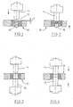
- a die 10 is shown, whose bore has a mold cavity 12, which is conical in cross-section. With the help of such a mold cavity 12, a compact can be produced, for example for a cutting plate, as in Fig. 5 is shown.
- the cutting plate after Fig. 5 has a clearance angle.
- the upper edge of the mold cavity 12 (die bore) from the top edge of the die 12 is spaced x.
- an upper punch 14 and below the die 10, a lower punch 16 is indicated.
- the stamps 14, 16 are actuated in a suitable manner, preferably with hydraulic press cylinders. These are controllable (not shown) to apply a desired force. In addition, they can be speed controlled to produce a desired force-time curve.
- Suitable force measuring devices which are associated with the punches 14, 16, determine the respectively applied pressing forces. Displacers, not shown, determine the positions of the upper and lower punches 14, 16 during the pressing process.
- the lower punch 16 When filling the die bore, the lower punch 16 has a predetermined filling position. Its position determines the filling quantity. Preferably, the position is initially slightly lower than the theoretical filling position for the predetermined amount, so that after filling the lower punch a certain distance can go up the column, so that the filling shoe, not shown, wipes excess material from the Matrizenoberseite. Subsequently, upper punch 14 and lower punch 16 are moved into the die bore, wherein the upper punch 14 moves in so far that it comes to rest on the upper side of the mold cavity 12. The entry depth into the die bore thus corresponds to the dimension x. The lower punch 16 is also moved to a predetermined position, as in Fig. 2 is shown. Subsequently, the pressing process takes place.
- FIG. 3 and FIG. 4 is different from the one after the Figures 1 and 2 in that the bore of the die is cylindrical.
- the cutting plate produced by means of the method has no clearance angle.
- Fig. 5 From the illustration to Fig. 5 It can be seen that the cutting plate 20, the cutting edge 22 adjacent two grooves 24, 26 has.
- the grooves are indicated here for illustration purposes only.
- Cutting plates of the type shown can be different Topographies on the top, which should improve the cutting behavior of the plate.
- the cutting edges 22 often have no linear extension, but are curved in space in a predetermined manner.
- a predetermined density can be generated.
- the energy input with the upper punch 14 corresponds to a predetermined value when the punch has reached its end position.
- the energy or applied work corresponds to the measured pressing force times the pressing path.
- this method does not proceed according to a predetermined setpoint curve for the pressing force, but is seen as achieving a constant energy input for all compacts.
- the pressing force of the lower punch is "nachiner" in accordance with the energy input from the upper punch. It can thereby happen that in the lower region of the sintered cutting plate 20 there is a density that deviates somewhat from the upper region. However, this is to be accepted if it is ensured that 20 precise dimensions are achieved for the upper portion of the cutting plate.
- a force-displacement diagram for the upper punch 14 is shown.
- the press force curve increases up to a maximum Presskraftwerg P max .
- the integral below this curve corresponds to the energy input E during the pressing process.
- the energy input E is composed of individual increments ⁇ E, and it is readily possible to control the upper punch 14 so that predetermined energy increments are entered.
- the energy ultimately used is less than the initially registered energy, because the compact shows a Auffederungs . It forms a kind of hysteresis, as in Fig. 6 shown.
- the area between the branches of the curve after. Fig. 6 forms the unused energy for the compression of the compact.
Abstract
Description
Die Erfindung bezieht sich auf ein Verfahren zur Herstellung von Pressteilen, insbesondere Schneidplatten aus Hartmetall durch Pressen von Metallpulver und anschließendes Sintern der Presslinge nach dem Patentanspruch 1.The invention relates to a method for the production of pressed parts, in particular cutting plates made of hard metal by pressing metal powder and subsequent sintering of the compacts according to claim 1.
Es ist bekannt, Formteile aus Hartmetall, Keramik, Sintermetall oder dergleichen mit Hilfe von Pressen herzustellen. Das Pulver- bzw. granuläre Material ist so bereitzustellen, dass bei einem angewandten Pressdruck der Pressling eine homogene Struktur bekommt und sich sintern lässt. Eine übliche Formgebung ist das sogenannte Direktpressen in entsprechend ausgeführten Pressformen oder Matrizen, denen ein Ober- und Unterstempel zugeordnet sind. Entsprechend dem jeweiligen Pressdruck ergibt sich beim Pressen eine unterschiedliche Dichte. Presslinge mit geringerer Dichte schwinden beim Sintern jedoch stärker als Presslinge mit höherer Dichte. Durch unterschiedlich einstellbare Presswege von Ober- und Unterstempel wird versucht, Dichteabweichungen zu minimieren. Andererseits können unterschiedliche Dichten in der Praxis durch unterschiedliche Presskräfte entstehen, die wiederum bei gleicher Höhe der Presslinge, z. B. durch Füllschwankungen, die bis zu einigen Prozenten gehen, hervorgerufen werden. Erschwerend bei der Herstellung von Presslingen, z. B. für Hartmetallschneidplatten, ist das Einhalten einer vorgegebenen Gesamthöhe zwischen Plattensitz und mindestens einer Schneidkante, die einen vorgegebenen Abstand zum Plattensitz aufweist.It is known to produce molded parts made of hard metal, ceramic, sintered metal or the like by means of presses. The powder or granular material is to be provided in such a way that, given an applied pressure, the compact gets a homogeneous structure and can be sintered. A common shape is the so-called direct pressing in correspondingly executed molds or dies, which are associated with an upper and lower punch. Depending on the particular pressing pressure results in a different density during pressing. However, lower density compacts shrink more strongly during sintering than higher density compacts. By differently adjustable pressing paths of upper and lower punch is trying to minimize density deviations. On the other hand, different densities can arise in practice by different pressing forces, which in turn at the same height of the compacts, z. B. caused by filling fluctuations that go up to a few percent. To make matters worse in the production of compacts, z. B. for carbide inserts, is the maintenance of a predetermined total height between the insert seat and at least one cutting edge having a predetermined distance from the insert seat.
Aus
Das Dokument
Aus
Es versteht sich, dass ein derartiges Verfahren nicht anwendbar ist, wenn eine vorgegebene Außenkontur des Presslings eingehalten werden muss.It is understood that such a method is not applicable if a predetermined outer contour of the compact must be complied with.
Wie schon erwähnt, ist die Einhaltung einer vorgegebenen Dichte eines Presslings von Bedeutung, da die Dichte hinterher den Schwund beim Sintern bestimmt. Die Dichte kann naturgemäß nur indirekt über die in das Material eingebrachte Presskraft ermittelt werden, was an sich bekannt ist. Hierbei ist zu berücksichtigen, dass die Presskraft bzw. die maximale Presskraft nicht völlig gleichzusetzen ist mit einer vorgegebenen Dichte, weil das Material des Presslings abhängig von seiner Beschaffenheit nach der Entlastung auffedert, sodass sich die Dichte ändert. Diese Änderung kann unter Umständen unerwünschte Einflüsse haben. Wird eine bestimmte Geometrie des Presslings eingehalten, ergeben sich unterschiedliche Presskraftwerte in Abhängigkeit von der Befüllmenge, aber auch in Abhängigkeit von der Homogenität des Pulvers im Pressling.As already mentioned, the adherence to a given density of a compact is important because the density subsequently determines the shrinkage during sintering. Naturally, the density can only be determined indirectly via the pressing force introduced into the material, which is known per se. It should be noted that the pressing force or the maximum pressing force is not completely equal to a given density, because the material of the compact springs depending on its nature after the relief springs, so that the density changes. This change may have undesirable effects. If a specific geometry of the compact is adhered to, different pressing force values result depending on the filling quantity, but also depending on the homogeneity of the powder in the compact.
Bei Presslingen mit unregelmäßiger Außenkontur, z.B. für Wendeschneidplatten, die auf der Oberseite Nuten oder Spanleitflächen oder dergleichen aufweisen, ergibt sich eine unterschiedliche Dichteverteilung auch während des Pressvorgangs. Da jedoch die Lage und der Verlauf der Schneidkante und der zugeordneten Topografie der Wendeschneidplatte wichtig sind, führt eine ungleiche Dichteverteilung zu unerwünschten Maßabweichungen beim Sintern.For compacts with an irregular outer contour, e.g. for indexable inserts, which have on the top grooves or Spanleitflächen or the like, results in a different density distribution even during the pressing process. However, since the location and course of the cutting edge and the associated topography of the insert are important, unequal density distribution leads to undesirable dimensional variations in sintering.
Aus
Aus
Der Erfindung liegt die Aufgabe zugrunde, ein Verfahren zur Herstellung von Pressteilen, insbesondere von Schneidplatten aus Hartmetall, durch Pressen von Metallpulver in Pulverpressen anzugeben, bei dem die Herstellung der Presslinge zu reproduzierbar genauen Erzeugnissen im Sinterverfahren führen.The invention has for its object to provide a method for producing pressed parts, in particular of cutting inserts made of hard metal, by pressing metal powder in powder presses, in which the production of the compacts lead to reproducible accurate products in the sintering process.
Diese Aufgabe wird durch die Merkmale des Patentanspruchs 1 gelöst.This object is solved by the features of patent claim 1.
Die Erfindung geht von der Erkenntnis aus, dass z.B. bei einer Wendeschneidplatte mit einer vorgegebenen Topografie im Bereich der Schneidkante und der Oberseite der obere Bereich des Presslings sensibel ist und daher besondere Sorgfalt bei der Erzielung der gewünschten Dichte in diesem Bereich aufgewendet werden muss. Dies geschieht bei der Erfindung dadurch, dass der Energieeintrag des Oberstempels in den oberen Bereich des Presslings vorgegeben wird. Findet dieser Energieeintrag im Wesentlichen in geregelter Weise statt, ist damit auch die gewünschte Dichte und die gleichmäßige Dichteverteilung in diesem Bereich gewährleistet. Es ist dann nicht so wichtig, ob der übrige Bereich des Presslings exakt mit der gleichen Dichte verpresst wird. Um jedoch auch in diesem Bereich eine zur Dichte im oberen Bereich angenäherte Dichte zu erhalten, wird der Gesamtenergieeintrag für den Pressling ermittelt. Beim Pressvorgang wird daher zunächst darauf geachtet, dass die mit dem Oberstempel eingetragene Energie reproduzierbar ist. Da über den Pressweg bei unterschiedlichen Befüllmengen eine Regelung über die Presskraft nicht erfolgt, wird, wie erwähnt, der Energieeintrag zugrunde gelegt und unterstellt, dass die gewünschte Dichte im oberen Bereich des Presslings erreicht worden ist, wenn der Energieeintrag einen vorgegebenen Wert hat. Der Unterstempel wird bei diesem Verfahren dem Oberstempel "nachgefahren", indem er nach Maßgabe des Restenergieeintrags vorgeschoben wird. Mit Restenergie ist diejenige Energie gemeint, die übrig bleibt, wenn von der vorgegebenen Gesamtenergie die vom Oberstempel eingetragene Energie abgezogen wird. Hierbei kann geschehen, dass die vorgegebene Dicke des Presslings nicht erreicht wird. Für diesen Fall ist an dem gesinterten Formling ein Nachbearbeiten erforderlich. Es ist unter Umständen aber auch nicht schädlich, wenn zur Erreichung der eingestellten Dicke der Energieeintrag des Unterstempels etwas höher wird, da der Einfluss auf die Verdichtung des oberen Bereiches vernachlässigbar ist.The invention is based on the recognition that, for example, in the case of an indexable insert having a predetermined topography in the area of the cutting edge and the top, the upper area of the compact is sensitive and therefore special care must be taken in achieving the desired density in this area. This is done in the invention in that the energy input of the upper punch is set in the upper part of the compact. If this energy input takes place essentially in a regulated manner, the desired density and the uniform density distribution in this area are guaranteed. It is then not so important whether the remaining area of the compact is compressed exactly with the same density. However, in order to obtain a density close to the density in the upper region, the total energy input for the compact is determined. During the pressing process, therefore, care is first taken to ensure that the energy entered with the top punch is reproducible. Since a control over the pressing force does not take place at different filling amounts over the pressing path, the energy input is taken as the basis and assumed that the desired density in the upper region of the compact has been reached when the energy input has a predetermined value. The lower punch is "nachgefahren" in this method the upper punch by being advanced in accordance with the residual energy input. Residual energy refers to the energy that remains when the energy entered by the upper stamp is deducted from the given total energy. This can happen that the predetermined thickness of the compact is not achieved. In this case, reworking is required on the sintered molding. Under certain circumstances, however, it may not be harmful if the energy input of the lower punch is slightly higher in order to reach the set thickness, since the influence on the compression of the upper portion is negligible.
Nach einer Ausgestaltung der Erfindung ist vorgesehen, dass der Verlauf des Energieeintrags über einen Pressweg des Oberstempels gespeichert und der Vorschub des Oberstempels nach Maßgabe dieses Verlaufes geregelt wird. Hierbei kann daran gedacht werden, die Gesamtenergie in einer Anzahl von Inkrementen aufzuteilen, nach denen dann eine Regelung des Vorschubs des Oberstempels möglich ist.According to one embodiment of the invention it is provided that the course of the energy input stored on a press travel of the upper punch and the feed of the upper punch is regulated in accordance with this course. Here, it can be thought of dividing the total energy in a number of increments, after which then a control of the feed of the upper punch is possible.
Für das Verpressen von Pulvermaterial, bei dem sich die Körner des Pulvers ineinander und miteinander "verkrallen", ist für die Erzielung einer gewünschten Dichte in erster Linie die Phase entscheidend, bei der bereits ein größerer Pressdruck aufgebracht wird. Daher sieht eine Ausgestaltung der Erfindung vor, dass erster und zweiter Wert für den Energieeintrag nur für die zweite Hälfte des Pressweges des Oberstempels gespeichert werden oder nur während der zweiten Hälfte des Pressvorgangs des Oberstempels der Energieeintrag von Ober- und Unterstempel mit den ersten und zweiten Werten verglichen werden. Es versteht sich, dass der Regelungsweg im Verhältnis zum Pressweg auch nahe an das Ende des Pressweges gelegt werden kann.For the compression of powder material, in which the grains of the powder into one another and "claw" with each other, is crucial to achieve a desired density, especially the phase in which already a greater pressing pressure is applied. Therefore, an embodiment of the invention provides that the first and second value for the energy input are stored only for the second half of the press path of the upper punch or only during the second half of the pressing operation of the upper punch the energy input of upper and lower punch with the first and second values be compared. It is understood that the control path in relation to the pressing path can also be placed close to the end of the pressing path.
Die Energie, die beim Pressen in einen Pressling eingetragen wird, ist das Produkt aus Kraft mal Pressweg. In Wirklichkeit ist jedoch die tatsächlich genutzte Energie nicht gleich diesem Produkt, sondern geringer, weil der Pressling auffedert, mithin ein Teil der Pressenergie nicht zur Verdichtung herangegezogen worden ist. Nach einer Ausgestaltung der Erfindung wird der Auffederweg des Presslings gemessen und daraus die nicht genutzte Energie berechnet. Diese Berechnung kann zur Korrektur beim Verpressen des nächsten Presslings herangezogen werden, wenn die tatsächlich genutzte Eintragenergie nicht einem vorgegebenen Wert entspricht. Durch Veränderung von Parametern beim Pressvorgang kann dann die eingetragene Energie verändert werden. Dies kann z.B. durch eine Änderung der Befüllung, durch unterschiedliche Verfahrwege des Füllschuhs, durch Vibration von Matrize, Unter- und/oder Oberstempel oder dergleichen erreicht werden.The energy that is entered into a compact during pressing is the product of force pressing. In reality, however, the energy actually used is not equal to this product, but lower because the compact has rebounded, and consequently part of the press energy has not been used for compaction. According to one embodiment of the invention, the Auffederweg of the compact is measured and calculated from the unused energy. This calculation can be used to correct the compression of the next compact if the actually used input energy does not correspond to a predetermined value. By changing parameters during the pressing process, the energy input can then be changed. This can be done, for example, by changing the filling, by different travels of the filling shoe to be achieved by vibration of the die, lower and / or upper punch or the like.
Die Erfindung soll nachfolgend anhand von Zeichnungen näher erläutert werden.
- Fig. 1
- zeigt eine Presse zum Verpressen von Metallpulver nach dem erfindungsgemäßen Verfahren vor dem eigentlichen Pressvorgang.
- Fig. 2
- zeigt die Presse nach
Fig. 1 während des Pressvorgangs. - Fig. 3
- zeigt eine abgewandelte Presse zur Durchführung des erfindungsgemäßen Verfahrens.
- Fig. 4
- zeigt die Presse nach
Fig. 3 während des Pressvorgangs. - Fig. 5
- zeigt einen Schnitt durch eine im Sinterverfahren hergestellte Schneidplatte in schematischer Darstellung.
- Fig. 6
- zeigt ein Kraft-Weg-Diagramm zur Illustration des erfindungsgemäßen Verfahrens.
- Fig. 1
- shows a press for pressing metal powder according to the inventive method before the actual pressing process.
- Fig. 2
- shows the press
Fig. 1 during the pressing process. - Fig. 3
- shows a modified press for carrying out the method according to the invention.
- Fig. 4
- shows the press
Fig. 3 during the pressing process. - Fig. 5
- shows a section through a cutting plate produced in the sintering process in a schematic representation.
- Fig. 6
- shows a force-displacement diagram for illustrating the method according to the invention.
In den
Bei der Befüllung der Matrizenbohrung hat der Unterstempel 16 eine vorgegebene Füllposition. Seine Position bestimmt die Füllmenge. Vorzugsweise ist die Position zu Beginn etwas niedriger als die theoretische Füllposition für die vorgegebene Menge, damit nach dem Befüllen der Unterstempel eine gewisse Strecke die Säule nach oben fahren kann, damit der nicht gezeigte Füllschuh überschüssiges Material von der Matrizenoberseite abstreift. Anschließend werden Oberstempel 14 und Unterstempel 16 in die Matrizenbohrung hineingefahren, wobei der Oberstempel 14 so weit hineinfährt, dass er an der Oberseite des Formhohlraums 12 zu liegen kommt. Die Einfahrtiefe in die Matrizenbohrung entspricht mithin dem Maß x. Der Unterstempel 16 wird ebenfalls auf eine vorgegebene Position verfahren, wie sie in
Aus der Darstellung nach
Erfindungsgemäß soll mit dem Oberstempel 14 im oberen Bereich der Schneidplatte 20, welcher nach unten durch die gestrichelte Linie 28 begrenzt ist, eine vorgegebene Dichte erzeugt werden. Hierzu ist erforderlich, dass der Energieeintrag mit dem Oberstempel 14 einem vorgegebenen Wert entspricht, wenn der Stempel seine Endposition erreicht hat. Die Energie oder die aufgebrachte Arbeit entspricht der gemessenen Presskraft mal dem Pressweg. Mithin wird bei diesem Verfahren nicht nach einer vorgegebenen Sollkurve für die Presskraft verfahren, sondern auf Erzielung eines gleichbleibenden Energieeintrags für alle Presslinge gesehen. Hierzu gehört, dass die Presskraft des Unterstempels durchaus unterschiedlich sein kann. Die Presskraft des Unterstempels wird nach Maßgabe des Energieeintrags vom Oberstempel "nachgefahren". Dadurch kann geschehen, dass im unteren Bereich der gesinterten Schneidplatte 20 eine vom oberen Bereich etwas abweichende Dichte herrscht . Dies ist jedoch in Kauf zu nehmen, wenn gewährleistet ist, dass für den oberen Bereich der Schneidplatte 20 präzise Abmessungen erzielt werden.According to the invention, with the
In
Claims (4)
- A process for the manufacture of compacts, particularly cemented-carbide cutting blades, by compressing metallic powder and subsequently sintering the compacts wherein the compacts are formed in a powder press having a die-plate (10), an upper ram (14) and at least one lower ram (16) which are associated with a die-bore and are adapted to be actuated by a hydraulic press cylinder with the rams (10, 14) associated thereto force-measuring devices and path-measuring devices to measure the compression forces during the ram feed motion up to the final positions, characterized in that the value of the energy to be applied by the upper ram (10) is stored for a compact of predetermined geometry and dimensions and a predetermined material, that the overall energy (E) to be applied by the upper and lower rams(10, 14) is further stored as a second value, that the feed motion of the upper ram (10) is completed when the energy applied by the ram has reached the predetermined first value and the feed motion of the lower ram (14) is effected depending on the application of the residual energy and is completed when the overall energy (E) has reached the predetermined second value.
- The process as claimed in claim 1, characterized in that the course of energy application is stored via a compacting path of the upper ram (10) and the feed rate of the upper ram (10) is regulated depending on this course.
- The process as claimed in claim 2, characterized in that the first and second values are stored only for the second half of the compacting path of the upper ram (10) or that the energy applied by the upper ram (10) is compared to the energy applied by the upper and lower ram (10, 14) only during the second half of the compressing operation.
- The process as claimed in any one of claims 1 to 3, characterized in that the spring-back path is measured for the compact upon completion of the compressing operation and the energy not utilized for compaction is calculated from the spring-back and is deducted from the overall energy (E) applied to deter-mine the real energy applied to the compact and at least one parameter influencing the compressing operation is varied during the next compressing operation if the real energy applied deviates from the predetermined second value.
Applications Claiming Priority (2)
| Application Number | Priority Date | Filing Date | Title |
|---|---|---|---|
| DE10142772A DE10142772C2 (en) | 2001-08-31 | 2001-08-31 | Process for the production of pressed parts in a powder press |
| DE10142772 | 2001-08-31 |
Publications (3)
| Publication Number | Publication Date |
|---|---|
| EP1287975A2 EP1287975A2 (en) | 2003-03-05 |
| EP1287975A3 EP1287975A3 (en) | 2004-01-28 |
| EP1287975B1 true EP1287975B1 (en) | 2008-04-02 |
Family
ID=7697312
Family Applications (1)
| Application Number | Title | Priority Date | Filing Date |
|---|---|---|---|
| EP02017011A Expired - Lifetime EP1287975B1 (en) | 2001-08-31 | 2002-07-27 | Process for producing molded parts in a powder press |
Country Status (4)
| Country | Link |
|---|---|
| US (1) | US7211217B2 (en) |
| EP (1) | EP1287975B1 (en) |
| AT (1) | ATE391004T1 (en) |
| DE (2) | DE10142772C2 (en) |
Families Citing this family (7)
| Publication number | Priority date | Publication date | Assignee | Title |
|---|---|---|---|---|
| DE102004008322B4 (en) * | 2004-02-20 | 2008-11-27 | Fette Gmbh | powder Press |
| JP4918999B2 (en) | 2006-05-19 | 2012-04-18 | クオリカプス株式会社 | Powder compression molding machine and continuous production apparatus for powder compression molding using the molding machine |
| DE102014105111A1 (en) * | 2014-04-10 | 2015-10-15 | Dorst Technologies Gmbh & Co. Kg | Pressure control device and method for controlling a pressure to be output for a ceramic and / or metal powder press |
| BE1023781B1 (en) * | 2016-05-18 | 2017-07-24 | Cnh Industrial Belgium Nv | RECTANGULAR BALL PRESS WITH AN IMPROVED SYSTEM AND AN IMPROVED CONTROL METHOD FOR CONTROLLING THE BALE FORM |
| CN106079513A (en) * | 2016-07-21 | 2016-11-09 | 太仓贝斯特机械设备有限公司 | A kind of high efficiency controllable type heat pressing forming device |
| CN111360248B (en) * | 2020-03-31 | 2023-04-18 | 珠海精磁新材料技术有限公司 | Improved generation one-die multi-cavity powder metallurgy forming die |
| EP4079427A1 (en) * | 2021-04-22 | 2022-10-26 | GKN Sinter Metals Engineering GmbH | Method for determining a parameter of a material and pressing tool for producing a green compact |
Family Cites Families (27)
| Publication number | Priority date | Publication date | Assignee | Title |
|---|---|---|---|---|
| US3687586A (en) * | 1970-04-22 | 1972-08-29 | Tamagawa Kikai Kinzoku Kk | Powder-forming press |
| US3640654A (en) * | 1970-06-25 | 1972-02-08 | Wolverine Pentronix | Die and punch assembly for compacting powder and method of assembly |
| US3826599A (en) * | 1972-06-01 | 1974-07-30 | Wolverine Pentronix | Adjusting mechanism and process for powder compacting press |
| US4260346A (en) * | 1979-10-09 | 1981-04-07 | Anderson Jr Raymond B | Press assembly for powder material |
| DE2951716A1 (en) * | 1979-12-19 | 1981-07-02 | Mannesmann AG, 4000 Düsseldorf | Pressing system to compensate for fluctuations - measures displacement of powder in mould simultaneously with pressure |
| US4443171A (en) * | 1982-04-14 | 1984-04-17 | Wesjay, Inc. | Multi-motion mechanical press |
| US4946634A (en) * | 1987-04-16 | 1990-08-07 | Gte Products Corporation | Powder compacting press to control green density distribution in parts |
| DE4009608A1 (en) * | 1989-04-07 | 1990-10-11 | Laeis & Bucher Gmbh | Impact press for ceramic mouldings - on feed-screw principle with specified checks of moulding thickness |
| DE3919847A1 (en) * | 1989-06-15 | 1990-12-20 | Mannesmann Ag | METHOD AND DEVICE FOR PRODUCING SIZED PRESSES |
| JPH07115233B2 (en) * | 1990-08-10 | 1995-12-13 | 株式会社ヨシツカ精機 | Powder molding press |
| JP3169247B2 (en) * | 1991-12-03 | 2001-05-21 | 株式会社石井工作研究所 | Pressing force automatic control method and device for press machine |
| DE4209767C1 (en) * | 1992-03-23 | 1993-05-06 | Mannesmann Ag, 4000 Duesseldorf, De | |
| GB9206526D0 (en) * | 1992-03-25 | 1992-05-06 | Komage Gellner & Co | Press apparatus |
| US5391069A (en) * | 1993-06-10 | 1995-02-21 | Bendzick; Ervin J. | Apparatus for compacting metal shavings |
| US5547360A (en) * | 1994-03-17 | 1996-08-20 | Tamagawa Machinery Co., Ltd. | Powder molding press |
| DE4428842C1 (en) * | 1994-08-02 | 1996-01-18 | Mannesmann Ag | Device for the production of compacts |
| DE19502596C2 (en) * | 1995-01-28 | 1997-08-28 | Fette Wilhelm Gmbh | Measuring device and computer for checking the tablets of the current production made on a rotary press |
| TW287975B (en) * | 1995-11-16 | 1996-10-11 | Honda Motor Co Ltd | Method of and apparatus for manufacturing pressed powder body |
| DE19717217C2 (en) * | 1997-04-24 | 1999-12-02 | Fette Wilhelm Gmbh | Method and device for producing compacts from hard metal, ceramic, sintered metal or the like |
| JP3059406B2 (en) * | 1997-08-27 | 2000-07-04 | 本田技研工業株式会社 | Compacting equipment |
| US5989487A (en) * | 1999-03-23 | 1999-11-23 | Materials Modification, Inc. | Apparatus for bonding a particle material to near theoretical density |
| JP3717714B2 (en) * | 1999-07-05 | 2005-11-16 | 本田技研工業株式会社 | Compaction molding method for helical gears |
| US6477945B1 (en) * | 1999-09-07 | 2002-11-12 | Aida Engineering, Ltd. | Double-action mechanical press |
| DE19958999A1 (en) * | 1999-12-08 | 2001-04-26 | Henkel Kgaa | Quality regulation method for pharmaceutical tablet manufacture compares tablet press energy value with reference value for press energy correction |
| SE515822C2 (en) * | 1999-12-30 | 2001-10-15 | Skf Nova Ab | Method and apparatus for compacting powdered metal bodies |
| US6531090B2 (en) * | 2000-02-17 | 2003-03-11 | Sumitomo Special Metals Co., Ltd. | Method for producing powder compact and method for manufacturing magnet |
| DE10010671C2 (en) * | 2000-03-04 | 2002-03-14 | Fette Wilhelm Gmbh | Process for producing pressed parts by pressing metal powder and then sintering the compact |
-
2001
- 2001-08-31 DE DE10142772A patent/DE10142772C2/en not_active Expired - Fee Related
-
2002
- 2002-07-27 EP EP02017011A patent/EP1287975B1/en not_active Expired - Lifetime
- 2002-07-27 DE DE50212003T patent/DE50212003D1/en not_active Expired - Fee Related
- 2002-07-27 AT AT02017011T patent/ATE391004T1/en not_active IP Right Cessation
- 2002-08-22 US US10/225,747 patent/US7211217B2/en not_active Expired - Fee Related
Also Published As
| Publication number | Publication date |
|---|---|
| EP1287975A3 (en) | 2004-01-28 |
| EP1287975A2 (en) | 2003-03-05 |
| US20030049147A1 (en) | 2003-03-13 |
| US7211217B2 (en) | 2007-05-01 |
| DE10142772A1 (en) | 2003-03-27 |
| DE10142772C2 (en) | 2003-09-25 |
| ATE391004T1 (en) | 2008-04-15 |
| DE50212003D1 (en) | 2008-05-15 |
Similar Documents
| Publication | Publication Date | Title |
|---|---|---|
| DE19717217C2 (en) | Method and device for producing compacts from hard metal, ceramic, sintered metal or the like | |
| DE69833396T2 (en) | Hydraulic press for the production of metal plates | |
| EP1566231B1 (en) | Powder press | |
| DE102015109805A1 (en) | Production of high-quality molds for metal casting (method and device) | |
| EP0403040B1 (en) | Method and apparatus for making dimensionally stable pressed articles | |
| DE102006020213B4 (en) | Press for producing compacts of powder material | |
| DE4209767C1 (en) | ||
| EP0353479B1 (en) | Method and apparatus for reducing the press load of a cutting press with positive stops | |
| EP1287975B1 (en) | Process for producing molded parts in a powder press | |
| EP0204266A1 (en) | Tablet-compressing machine | |
| EP1129802B2 (en) | Process for controlling the pressing force for metal powder compression | |
| EP1287978A2 (en) | Process and apparatus for metal powder compression in a pressed body | |
| DE3715077C2 (en) | ||
| EP0367035A1 (en) | Press or punching machine | |
| DE10142773C1 (en) | Hydraulic press for pressing metal powder | |
| EP1277564B1 (en) | Method of compacting powder materials | |
| DE19903417B4 (en) | Method for filling a hydraulic press with powders | |
| EP0428780B1 (en) | Punch press with correction value input for the penetration depth and the feed length | |
| DE102004012858B4 (en) | Roller body manufacturing method for roller bearing, involves measuring weight or volume of raw blocks, and feeding blocks in to pressing tool, where blocks are shaped in tool in two stages and deformed by stamp that penetrates in to tool | |
| EP0401501B1 (en) | Method for influencing the movement of the frontal flow during pressing of materials and apparatus for carrying out the method | |
| DE2915966A1 (en) | Compression force measuring device for hydraulic press - uses two symmetrically-spaced pressure capsules or expansion strips | |
| DE19545753B4 (en) | Regulation of frame position and pressing pressure in molding plants | |
| DE19955196A1 (en) | Method to maintain breaking resistance of e.g. washing powder tablets etc. with constant automatic adaptation of dosing resp. compacting rollers to compensate for charging variations | |
| EP1287977A2 (en) | Process and apparatus for minimizing the spread of maximum pressing forces in a powder press | |
| DE102017119342A1 (en) | Method for controlling a metal or ceramic powder press with automatic trajectory generation |
Legal Events
| Date | Code | Title | Description |
|---|---|---|---|
| PUAI | Public reference made under article 153(3) epc to a published international application that has entered the european phase |
Free format text: ORIGINAL CODE: 0009012 |
|
| AK | Designated contracting states |
Kind code of ref document: A2 Designated state(s): AT BE BG CH CY CZ DE DK EE ES FI FR GB GR IE IT LI LU MC NL PT SE SK TR |
|
| AX | Request for extension of the european patent |
Extension state: AL LT LV MK RO SI |
|
| PUAL | Search report despatched |
Free format text: ORIGINAL CODE: 0009013 |
|
| AK | Designated contracting states |
Kind code of ref document: A3 Designated state(s): AT BE BG CH CY CZ DE DK EE ES FI FR GB GR IE IT LI LU MC NL PT SE SK TR |
|
| AX | Request for extension of the european patent |
Extension state: AL LT LV MK RO SI |
|
| RIC1 | Information provided on ipc code assigned before grant |
Ipc: 7B 30B 11/00 A Ipc: 7B 22F 3/02 B Ipc: 7B 30B 15/22 B |
|
| 17P | Request for examination filed |
Effective date: 20031218 |
|
| 17Q | First examination report despatched |
Effective date: 20040330 |
|
| AKX | Designation fees paid |
Designated state(s): AT BE BG CH CY CZ DE DK EE ES FI FR GB GR IE IT LI LU MC NL PT SE SK TR |
|
| GRAP | Despatch of communication of intention to grant a patent |
Free format text: ORIGINAL CODE: EPIDOSNIGR1 |
|
| GRAS | Grant fee paid |
Free format text: ORIGINAL CODE: EPIDOSNIGR3 |
|
| GRAA | (expected) grant |
Free format text: ORIGINAL CODE: 0009210 |
|
| AK | Designated contracting states |
Kind code of ref document: B1 Designated state(s): AT BE BG CH CY CZ DE DK EE ES FI FR GB GR IE IT LI LU MC NL PT SE SK TR |
|
| REG | Reference to a national code |
Ref country code: GB Ref legal event code: FG4D Free format text: NOT ENGLISH |
|
| REG | Reference to a national code |
Ref country code: IE Ref legal event code: FG4D Free format text: LANGUAGE OF EP DOCUMENT: GERMAN Ref country code: CH Ref legal event code: EP |
|
| REF | Corresponds to: |
Ref document number: 50212003 Country of ref document: DE Date of ref document: 20080515 Kind code of ref document: P |
|
| REG | Reference to a national code |
Ref country code: SE Ref legal event code: TRGR |
|
| REG | Reference to a national code |
Ref country code: CH Ref legal event code: NV Representative=s name: ISLER & PEDRAZZINI AG |
|
| NLV1 | Nl: lapsed or annulled due to failure to fulfill the requirements of art. 29p and 29m of the patents act | ||
| REG | Reference to a national code |
Ref country code: IE Ref legal event code: FD4D |
|
| PG25 | Lapsed in a contracting state [announced via postgrant information from national office to epo] |
Ref country code: PT Free format text: LAPSE BECAUSE OF FAILURE TO SUBMIT A TRANSLATION OF THE DESCRIPTION OR TO PAY THE FEE WITHIN THE PRESCRIBED TIME-LIMIT Effective date: 20080902 Ref country code: NL Free format text: LAPSE BECAUSE OF FAILURE TO SUBMIT A TRANSLATION OF THE DESCRIPTION OR TO PAY THE FEE WITHIN THE PRESCRIBED TIME-LIMIT Effective date: 20080402 Ref country code: FI Free format text: LAPSE BECAUSE OF FAILURE TO SUBMIT A TRANSLATION OF THE DESCRIPTION OR TO PAY THE FEE WITHIN THE PRESCRIBED TIME-LIMIT Effective date: 20080402 Ref country code: ES Free format text: LAPSE BECAUSE OF FAILURE TO SUBMIT A TRANSLATION OF THE DESCRIPTION OR TO PAY THE FEE WITHIN THE PRESCRIBED TIME-LIMIT Effective date: 20080713 Ref country code: BG Free format text: LAPSE BECAUSE OF FAILURE TO SUBMIT A TRANSLATION OF THE DESCRIPTION OR TO PAY THE FEE WITHIN THE PRESCRIBED TIME-LIMIT Effective date: 20080702 |
|
| ET | Fr: translation filed | ||
| PG25 | Lapsed in a contracting state [announced via postgrant information from national office to epo] |
Ref country code: CZ Free format text: LAPSE BECAUSE OF FAILURE TO SUBMIT A TRANSLATION OF THE DESCRIPTION OR TO PAY THE FEE WITHIN THE PRESCRIBED TIME-LIMIT Effective date: 20080402 Ref country code: DK Free format text: LAPSE BECAUSE OF FAILURE TO SUBMIT A TRANSLATION OF THE DESCRIPTION OR TO PAY THE FEE WITHIN THE PRESCRIBED TIME-LIMIT Effective date: 20080402 Ref country code: IE Free format text: LAPSE BECAUSE OF FAILURE TO SUBMIT A TRANSLATION OF THE DESCRIPTION OR TO PAY THE FEE WITHIN THE PRESCRIBED TIME-LIMIT Effective date: 20080402 |
|
| PLBE | No opposition filed within time limit |
Free format text: ORIGINAL CODE: 0009261 |
|
| STAA | Information on the status of an ep patent application or granted ep patent |
Free format text: STATUS: NO OPPOSITION FILED WITHIN TIME LIMIT |
|
| PG25 | Lapsed in a contracting state [announced via postgrant information from national office to epo] |
Ref country code: SK Free format text: LAPSE BECAUSE OF FAILURE TO SUBMIT A TRANSLATION OF THE DESCRIPTION OR TO PAY THE FEE WITHIN THE PRESCRIBED TIME-LIMIT Effective date: 20080402 |
|
| 26N | No opposition filed |
Effective date: 20090106 |
|
| PG25 | Lapsed in a contracting state [announced via postgrant information from national office to epo] |
Ref country code: MC Free format text: LAPSE BECAUSE OF NON-PAYMENT OF DUE FEES Effective date: 20080731 |
|
| PG25 | Lapsed in a contracting state [announced via postgrant information from national office to epo] |
Ref country code: EE Free format text: LAPSE BECAUSE OF FAILURE TO SUBMIT A TRANSLATION OF THE DESCRIPTION OR TO PAY THE FEE WITHIN THE PRESCRIBED TIME-LIMIT Effective date: 20080402 |
|
| PG25 | Lapsed in a contracting state [announced via postgrant information from national office to epo] |
Ref country code: CY Free format text: LAPSE BECAUSE OF FAILURE TO SUBMIT A TRANSLATION OF THE DESCRIPTION OR TO PAY THE FEE WITHIN THE PRESCRIBED TIME-LIMIT Effective date: 20080402 |
|
| PGFP | Annual fee paid to national office [announced via postgrant information from national office to epo] |
Ref country code: FR Payment date: 20090729 Year of fee payment: 8 |
|
| PGFP | Annual fee paid to national office [announced via postgrant information from national office to epo] |
Ref country code: AT Payment date: 20090729 Year of fee payment: 8 Ref country code: CH Payment date: 20090730 Year of fee payment: 8 Ref country code: DE Payment date: 20090909 Year of fee payment: 8 Ref country code: GB Payment date: 20090701 Year of fee payment: 8 Ref country code: LU Payment date: 20090710 Year of fee payment: 8 Ref country code: SE Payment date: 20090730 Year of fee payment: 8 |
|
| PGFP | Annual fee paid to national office [announced via postgrant information from national office to epo] |
Ref country code: IT Payment date: 20090723 Year of fee payment: 8 |
|
| PG25 | Lapsed in a contracting state [announced via postgrant information from national office to epo] |
Ref country code: BE Free format text: LAPSE BECAUSE OF NON-PAYMENT OF DUE FEES Effective date: 20080731 |
|
| PG25 | Lapsed in a contracting state [announced via postgrant information from national office to epo] |
Ref country code: TR Free format text: LAPSE BECAUSE OF FAILURE TO SUBMIT A TRANSLATION OF THE DESCRIPTION OR TO PAY THE FEE WITHIN THE PRESCRIBED TIME-LIMIT Effective date: 20080402 |
|
| PG25 | Lapsed in a contracting state [announced via postgrant information from national office to epo] |
Ref country code: GR Free format text: LAPSE BECAUSE OF FAILURE TO SUBMIT A TRANSLATION OF THE DESCRIPTION OR TO PAY THE FEE WITHIN THE PRESCRIBED TIME-LIMIT Effective date: 20080703 |
|
| REG | Reference to a national code |
Ref country code: CH Ref legal event code: PL |
|
| GBPC | Gb: european patent ceased through non-payment of renewal fee |
Effective date: 20100727 |
|
| REG | Reference to a national code |
Ref country code: FR Ref legal event code: ST Effective date: 20110331 |
|
| PG25 | Lapsed in a contracting state [announced via postgrant information from national office to epo] |
Ref country code: DE Free format text: LAPSE BECAUSE OF NON-PAYMENT OF DUE FEES Effective date: 20110201 Ref country code: LI Free format text: LAPSE BECAUSE OF NON-PAYMENT OF DUE FEES Effective date: 20100731 Ref country code: CH Free format text: LAPSE BECAUSE OF NON-PAYMENT OF DUE FEES Effective date: 20100731 |
|
| REG | Reference to a national code |
Ref country code: DE Ref legal event code: R119 Ref document number: 50212003 Country of ref document: DE Effective date: 20110201 |
|
| PG25 | Lapsed in a contracting state [announced via postgrant information from national office to epo] |
Ref country code: FR Free format text: LAPSE BECAUSE OF NON-PAYMENT OF DUE FEES Effective date: 20100802 Ref country code: IT Free format text: LAPSE BECAUSE OF NON-PAYMENT OF DUE FEES Effective date: 20100727 Ref country code: AT Free format text: LAPSE BECAUSE OF NON-PAYMENT OF DUE FEES Effective date: 20100727 |
|
| PG25 | Lapsed in a contracting state [announced via postgrant information from national office to epo] |
Ref country code: GB Free format text: LAPSE BECAUSE OF NON-PAYMENT OF DUE FEES Effective date: 20100727 |
|
| PG25 | Lapsed in a contracting state [announced via postgrant information from national office to epo] |
Ref country code: SE Free format text: LAPSE BECAUSE OF NON-PAYMENT OF DUE FEES Effective date: 20100728 Ref country code: LU Free format text: LAPSE BECAUSE OF NON-PAYMENT OF DUE FEES Effective date: 20100727 |