EP1566123B1 - Geräuschminderung in Wasserkochkesseln - Google Patents
Geräuschminderung in Wasserkochkesseln Download PDFInfo
- Publication number
- EP1566123B1 EP1566123B1 EP05250980A EP05250980A EP1566123B1 EP 1566123 B1 EP1566123 B1 EP 1566123B1 EP 05250980 A EP05250980 A EP 05250980A EP 05250980 A EP05250980 A EP 05250980A EP 1566123 B1 EP1566123 B1 EP 1566123B1
- Authority
- EP
- European Patent Office
- Prior art keywords
- heater
- coating
- water
- weight
- region
- Prior art date
- Legal status (The legal status is an assumption and is not a legal conclusion. Google has not performed a legal analysis and makes no representation as to the accuracy of the status listed.)
- Expired - Lifetime
Links
- XLYOFNOQVPJJNP-UHFFFAOYSA-N water Substances O XLYOFNOQVPJJNP-UHFFFAOYSA-N 0.000 title claims abstract description 22
- 230000009467 reduction Effects 0.000 title claims abstract description 20
- 238000010438 heat treatment Methods 0.000 title claims description 19
- 238000011282 treatment Methods 0.000 claims abstract description 12
- 238000000576 coating method Methods 0.000 claims description 90
- 239000011248 coating agent Substances 0.000 claims description 82
- 238000000034 method Methods 0.000 claims description 43
- 239000002245 particle Substances 0.000 claims description 31
- 239000000654 additive Substances 0.000 claims description 19
- 230000000996 additive effect Effects 0.000 claims description 19
- 239000004810 polytetrafluoroethylene Substances 0.000 claims description 16
- 229920001343 polytetrafluoroethylene Polymers 0.000 claims description 16
- 239000011159 matrix material Substances 0.000 claims description 15
- 239000004695 Polyether sulfone Substances 0.000 claims description 13
- 229920006393 polyether sulfone Polymers 0.000 claims description 13
- 239000010445 mica Substances 0.000 claims description 12
- 229910052618 mica group Inorganic materials 0.000 claims description 12
- GWEVSGVZZGPLCZ-UHFFFAOYSA-N Titan oxide Chemical compound O=[Ti]=O GWEVSGVZZGPLCZ-UHFFFAOYSA-N 0.000 claims description 11
- 239000007921 spray Substances 0.000 claims description 10
- 239000000945 filler Substances 0.000 claims description 9
- VYPSYNLAJGMNEJ-UHFFFAOYSA-N Silicium dioxide Chemical compound O=[Si]=O VYPSYNLAJGMNEJ-UHFFFAOYSA-N 0.000 claims description 7
- 239000004734 Polyphenylene sulfide Substances 0.000 claims description 4
- 239000004411 aluminium Substances 0.000 claims description 4
- XAGFODPZIPBFFR-UHFFFAOYSA-N aluminium Chemical compound [Al] XAGFODPZIPBFFR-UHFFFAOYSA-N 0.000 claims description 4
- 229910052782 aluminium Inorganic materials 0.000 claims description 4
- 230000006911 nucleation Effects 0.000 claims description 4
- 238000010899 nucleation Methods 0.000 claims description 4
- 229920000139 polyethylene terephthalate Polymers 0.000 claims description 4
- 239000005020 polyethylene terephthalate Substances 0.000 claims description 4
- 229920000069 polyphenylene sulfide Polymers 0.000 claims description 4
- -1 polysiloxane Polymers 0.000 claims description 4
- 239000011521 glass Substances 0.000 claims description 3
- 239000010453 quartz Substances 0.000 claims description 3
- 238000001179 sorption measurement Methods 0.000 claims description 3
- 239000004593 Epoxy Substances 0.000 claims description 2
- 239000000049 pigment Substances 0.000 claims description 2
- 229920001296 polysiloxane Polymers 0.000 claims description 2
- 239000000377 silicon dioxide Substances 0.000 claims description 2
- 239000007788 liquid Substances 0.000 claims 2
- 238000009835 boiling Methods 0.000 description 16
- 239000000463 material Substances 0.000 description 9
- 230000008569 process Effects 0.000 description 8
- 239000000758 substrate Substances 0.000 description 8
- 238000007766 curtain coating Methods 0.000 description 7
- 230000000694 effects Effects 0.000 description 5
- 230000015572 biosynthetic process Effects 0.000 description 4
- 238000009792 diffusion process Methods 0.000 description 4
- 238000005755 formation reaction Methods 0.000 description 4
- 238000005507 spraying Methods 0.000 description 4
- 238000007761 roller coating Methods 0.000 description 3
- 229910001220 stainless steel Inorganic materials 0.000 description 3
- 239000010935 stainless steel Substances 0.000 description 3
- 230000008901 benefit Effects 0.000 description 2
- 230000008021 deposition Effects 0.000 description 2
- 239000006185 dispersion Substances 0.000 description 2
- 239000000203 mixture Substances 0.000 description 2
- 229920000642 polymer Polymers 0.000 description 2
- NIXOWILDQLNWCW-UHFFFAOYSA-M Acrylate Chemical compound [O-]C(=O)C=C NIXOWILDQLNWCW-UHFFFAOYSA-M 0.000 description 1
- 229920012266 Poly(ether sulfone) PES Polymers 0.000 description 1
- BLRPTPMANUNPDV-UHFFFAOYSA-N Silane Chemical compound [SiH4] BLRPTPMANUNPDV-UHFFFAOYSA-N 0.000 description 1
- 230000002411 adverse Effects 0.000 description 1
- 229920005601 base polymer Polymers 0.000 description 1
- 230000009286 beneficial effect Effects 0.000 description 1
- 230000008859 change Effects 0.000 description 1
- 239000003795 chemical substances by application Substances 0.000 description 1
- 238000010276 construction Methods 0.000 description 1
- 238000005260 corrosion Methods 0.000 description 1
- 230000007797 corrosion Effects 0.000 description 1
- 238000007598 dipping method Methods 0.000 description 1
- KPUWHANPEXNPJT-UHFFFAOYSA-N disiloxane Chemical class [SiH3]O[SiH3] KPUWHANPEXNPJT-UHFFFAOYSA-N 0.000 description 1
- JBKVHLHDHHXQEQ-UHFFFAOYSA-N epsilon-caprolactam Chemical group O=C1CCCCCN1 JBKVHLHDHHXQEQ-UHFFFAOYSA-N 0.000 description 1
- 238000009472 formulation Methods 0.000 description 1
- 238000013021 overheating Methods 0.000 description 1
- 239000011236 particulate material Substances 0.000 description 1
- 230000002028 premature Effects 0.000 description 1
- 230000000717 retained effect Effects 0.000 description 1
- 238000007650 screen-printing Methods 0.000 description 1
- 229910000077 silane Inorganic materials 0.000 description 1
- 238000004381 surface treatment Methods 0.000 description 1
- 239000004408 titanium dioxide Substances 0.000 description 1
- 238000004078 waterproofing Methods 0.000 description 1
Images

Classifications
-
- H—ELECTRICITY
- H05—ELECTRIC TECHNIQUES NOT OTHERWISE PROVIDED FOR
- H05B—ELECTRIC HEATING; ELECTRIC LIGHT SOURCES NOT OTHERWISE PROVIDED FOR; CIRCUIT ARRANGEMENTS FOR ELECTRIC LIGHT SOURCES, IN GENERAL
- H05B1/00—Details of electric heating devices
- H05B1/02—Automatic switching arrangements specially adapted to apparatus ; Control of heating devices
- H05B1/0227—Applications
- H05B1/0252—Domestic applications
- H05B1/0258—For cooking
- H05B1/0269—For heating of fluids
-
- A—HUMAN NECESSITIES
- A47—FURNITURE; DOMESTIC ARTICLES OR APPLIANCES; COFFEE MILLS; SPICE MILLS; SUCTION CLEANERS IN GENERAL
- A47J—KITCHEN EQUIPMENT; COFFEE MILLS; SPICE MILLS; APPARATUS FOR MAKING BEVERAGES
- A47J27/00—Cooking-vessels
- A47J27/21—Water-boiling vessels, e.g. kettles
- A47J27/21008—Water-boiling vessels, e.g. kettles electrically heated
- A47J27/21041—Water-boiling vessels, e.g. kettles electrically heated with heating elements arranged outside the water vessel
-
- A—HUMAN NECESSITIES
- A47—FURNITURE; DOMESTIC ARTICLES OR APPLIANCES; COFFEE MILLS; SPICE MILLS; SUCTION CLEANERS IN GENERAL
- A47J—KITCHEN EQUIPMENT; COFFEE MILLS; SPICE MILLS; APPARATUS FOR MAKING BEVERAGES
- A47J27/00—Cooking-vessels
- A47J27/21—Water-boiling vessels, e.g. kettles
- A47J27/21166—Constructional details or accessories
-
- A—HUMAN NECESSITIES
- A47—FURNITURE; DOMESTIC ARTICLES OR APPLIANCES; COFFEE MILLS; SPICE MILLS; SUCTION CLEANERS IN GENERAL
- A47J—KITCHEN EQUIPMENT; COFFEE MILLS; SPICE MILLS; APPARATUS FOR MAKING BEVERAGES
- A47J36/00—Parts, details or accessories of cooking-vessels
- A47J36/02—Selection of specific materials, e.g. heavy bottoms with copper inlay or with insulating inlay
-
- H—ELECTRICITY
- H05—ELECTRIC TECHNIQUES NOT OTHERWISE PROVIDED FOR
- H05B—ELECTRIC HEATING; ELECTRIC LIGHT SOURCES NOT OTHERWISE PROVIDED FOR; CIRCUIT ARRANGEMENTS FOR ELECTRIC LIGHT SOURCES, IN GENERAL
- H05B3/00—Ohmic-resistance heating
- H05B3/78—Heating arrangements specially adapted for immersion heating
Definitions
- This invention relates to electric water heaters and to vessels incorporating such heaters which are adapted to reduce the amount of noise generated during heating.
- GB-A-2386532 the Applicant set out details of various coatings that can be applied to the water-facing surface of an electric water heater in order to reduce the incidence of local nucleate boiling and thus reduce the amount of noise generated.
- JP 9-23976 An alternative way of reducing boiling noise is disclosed in JP 9-23976 .
- the heating base of the vessel is formed with a plurality of projections.
- the present invention provides an electric water heater comprising a noise reduction coating only on part of its water-facing surface such that a region of the water-facing surface intended in use to be directly above a thermal sensor is substantially free of said coating.
- the invention extends to a method of applying a treatment to an electric water heater comprising applying a coating to only a part of the water-facing surface of the heater such that a region of the surface intended to be directly above a thermal sensor in use is left without said coating.
- the invention also extends to a water heating vessel, preferably a water boiling vessel, incorporating such a heater; and to a heater as defined herein with at least one thermal sensor directly beneath said uncoated region.
- the coating covers at least the portion of the water heating surface directly above the heater so that the degree of noise reduction need not be significantly adversely affected.
- the coating pattern has the shape of an annulus leaving the centre of the heater surface uncoated so as to correspond generally to the standard shape of a sheathed heating element attached to the underside of the heater.
- the coating may comprise any coating giving a noise-reducing effect but preferably the coating is one giving rise to adjacent micro-regions with different surface properties, preferably different surface tension properties, as specified in GB-A-2386532 .
- the coating may be applied in any convenient way, e.g. using a mask and spray or screen printing.
- the liquid-facing surface of the heater is raised in the coated region. This is beneficial since if the region of the heater which is to receive the coating is raised above the rest of the heater, the coating may simply be applied by a roller without the need to mask the rest of the heater. Where as is preferred the coating is over the element, the additional advantage is achieved that the corresponding recess on the dry side of the heater can help to locate the element during assembly.
- Methods of making heaters as disclosed herein preferably include the step of providing a heater having a raised portion and applying said noise reduction coating only to said raised portion.
- the heater surface treatment comprises a coating to provide the necessary surface properties.
- a coating may, for example, be a two-phase or a multi-phase coating, comprising particles which provide nucleation sites for bubbles and a matrix acting to disrupt the growth of the bubbles.
- the particle size is also important in the operation of the coating. If the particles are too small, they may be completely retained within the coating matrix and thus not penetrate the surface and thus not act as nucleation sites for bubble formation.
- the additive particle size is less than 0.5 mm. Preferably it is above 20 microns, more preferably more above 50 microns and most preferably between 100 and 300 microns.
- a particularly suitable additive is one in which 50-75% of the particles pass through a 45 micron mesh opening size, 93-99% through a 90 micron opening and 100% through a 150 micron mesh size (i.e. a nominal 150 ⁇ m size).
- the method of coating deposition also has an influence on the size of additive particles.
- spray or roller coating it has been found that a smaller additive particle size may be used successfully than that used in a curtain coating process in which a "curtain" of coating material falls onto a moving substrate. This may be due to the curtain coating method leading to align particles in a certain direction as the coating flows and settles on the substrate.
- a nominal 150 ⁇ m additive size may be used in a spray or roller process
- a nominal 250 ⁇ m size may be needed in a curtain coating process.
- a so-called "dry” spraying process is preferred in some circumstances in that it promotes the deposition of the particles nearer the surface.
- the spray process is performed with a higher percentage of air in the spray mix than is traditional, and the spray head held away from the surface being coated by typically 20-30 cm.
- the average spacing between particles should preferably be of the same order as the particle size.
- the particles are preferably inorganic such as mica, aluminium, silica, glass, quartz or so on.
- particulate material for example mica
- the performance of certain particulate material degrades with an associated increase in the sound levels.
- more stable materials such as quartz or glass may be used.
- the performance of other materials can be significantly improved by treatment to reduce or prevent water adsorption onto the particle surface.
- the particulate additive is pre-treated to reduce water adsorption onto the additive surface.
- the additive particles may therefore be treated with a waterproofing agent such as silane or siloxane, which are widely available commercially.
- a waterproofing agent such as silane or siloxane
- the additive particles may be treated with materials which are typically used in coating products containing aluminium flakes in order to reduce the aluminium corrosion. Examples of such treatments include the use of polymer coated acrylate and polymer coated resist which also posses dielectric properties. These materials and processes are available commercially from Eckart GmbH.
- the particles constitute less than about 3% by weight of the finished coating, more preferably about 1-3% by weight.
- the particles may therefore comprise typically less than about 1% by weight of the coating prior to application, and more preferably between about 0.3-1% by weight. This is found to optimise both the sound and scale performance of the heater.
- the method of application may also influence the percentage of additive in the coating.
- a figure of approximately 1% by weight of applied and cured coating might be used in a spray or roller coating method, a figure of approximately 3% by weight may be more appropriate in a curtain coating process.
- the problem with adding too much particulate to the coating is that it will promote adhesion of scale.
- This effect can be alleviated by adding a scale shedding additive such as PTFE to the coating.
- a scale shedding additive such as PTFE
- PTFE scale shedding additive
- the matrix may be organic or inorganic, but it is preferably organic, for example PTFE, PES (polyethersulfone), polysiloxane, PPS (polyphenylene sulfide), epoxy or PET (polyethylene terephthalate).
- the matrix may contain fillers, such as pigments, as is known in the coating art.
- the matrix is preferably a material which has good scale release properties, such as Greblon®.
- a coating which has been found to be suitable is Chemlon X7541A produced by Akzo Nobel.
- This coating comprises a base polymer matrix consisting of 80% PES 20% PTFE, with 2% by weight of mica particles added.
- the coating is preferably 5-50 microns thick, more preferably 5-25 microns thick and most preferably 10-20 microns thick and may be applied by any suitable method, for example spraying, dipping, roller or curtain coating.
- a finished coating which is particularly suited for planar thick film heaters is a PES matrix containing a TiO 2 filler (typically 85-90% by weight PES, 5-10% by weight filler), 1-3% by weight mica particles, and 0.1% by weight PTFE.
- a figure of 1% mica particles is suitable for spray or roller application while 3% is more appropriate for curtain coating application.
- Thick film heaters are quite sensitive to film boiling, as the temperature of the heater substrate can rise very rapidly when film boiling occurs, leading to inadvertent operation of a control associated with the heater. Accordingly the percentage of PTFE is relatively low.
- a formulation which is particularly suited to planar elements comprising a metallic substrate with a sheathed heating element secured thereto comprises, as before, PES matrix with TiO 2 filler, 1% by weight mica and 0.3% by weight PTFE.
- Such coatings would normally be sprayed due to edge formations on the heater (such as mounting formations as disclosed in WO 96/18331 ) preventing a curtain coating method being used.
- a sheathed element construction is less sensitive to film boiling, as its thermal capacity tends to be greater than that of a thick film heating element, so a higher percentage of PTFE can be used in this coating.
- the coatings may be prepared by mixing together dispersions of PES, TiO 2 and PTFE and mica in the appropriate percentages to give the desired percentages of components in the finished coating.
- the coating may be applied to a substrate using a spray, roller or other coating technique as appropriate.
- the substrate is typically stainless steel, for example a 300 or 400 series stainless steel and is typically a plate of 0.5-1.5mm thickness.
- the substrate is preferably grit blasted to a roughness of 2.5-3.0 Ra and degreased.
- the coating is cured for 10 minutes at 375EC.
- uncoated region is used herein this should be understood to mean a region of the heater surface which is substantially free of the noise reduction coating, which is applied elsewhere on the heater. Such an “uncoated region” may have one or more other coatings performing other functions.
- the uncoated region of the heater set out herein may overlie a single thermal sensor, in which case the thermal sensor is preferably a primary overheat sensor since this is normally arranged to operate at a lower temperature than a secondary thermal sensor and is thus more prone to DBI.
- the uncoated region corresponds to both or all thermal sensors provided.
- the uncoated region need not be in one piece but could comprise two separate uncoated areas.
- the coating may be in a plurality of discrete areas rather than a continuous region.
- the thermal sensor beneath the uncoated region in use could be of any known type, for example a bimetallic actuator, thermal fuse, thermistor etc.
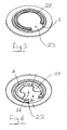
- the Figures show a generally standard sheathed underfloor heating element which comprises a generally dish-shaped plate 2 to the underside of which is mounted a sheathed electrical resistance element 4 with a disc-shaped thermal diffuser plate 6 sandwiched between them.
- the plate 2 is made from stainless steel as is well known in the art.
- the water-facing surface of the heater 2a is treated by applying a region of noise reduction coating 8 which is annular in shape.
- the noise-reduction coating 8 may be formed of any of the materials set out in GB-A-2386532 .
- the coating may be a polyethersulfone (PES) matrix with titanium dioxide filler with 1% by weight mica and 0.3% by weight PTFE.
- the coating 8 overlies the heating element sheath 4.
- the coating 8 defines a circular central region 10 which does not have the coating.
- the two bimetallic actuators 12 of one of the Applicant's U17 or U18 series of controls are located in use beneath this uncoated region.
- heat from the element 4 will be transferred to the water predominantly by means of a direct path through the heat diffuser plate 6 and the heater plate 2 and the coating 8 thereon. Even if the heater 4 is of a modern high powered variety such as with a rating of 3kW, the adjacent regions of differing surface tension properties at a microscopic level in the coated region 8 will substantially reduce the size to which bubbles grow during nucleate boiling and therefore the noise which is generated. Since there is a shorter thermal path directly through the diffuser plate 6 and heater plate 2 than one involving the lateral conduction of heat by the diffuser plate 6, heat transfer from the central region 10 to the water will be relatively low and thus no significant noise will be generated by such transfer.
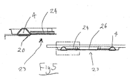
- Figs 3 to 5 a further embodiment of the invention is shown.
- the noise reduction coating 20 is applied to a raised region 22 of the heater plate 23.
- the sheathed element 4 is received in a recess on the dry side formed by the raised region 22. This enables the coating 20 to be applied simply using a flat roller without the need to use a mask since the rest of the heater surface 23 will not come into contact with the roller.
- the sheathed element 4 is in direct contact with the heater plate 23 - i.e. there is no diffusion plate between them.
- a heat diffusion member 24 inwardly of the element 4 which is approximately C-shaped and partly surrounds a region 26 inwardly thereof with no heat diffusion member.
- the heat diffusion member 24 is in good thermal contact with the heater plate 23 and the side wall of the sheathed element 4. This represents a cost reduction over the diffuser plate 6 of the first embodiment.
- the coated region need not have the shape shown and could be any suitable noise reducing material.
- the noise reduction coating is preferably one of the ones set out in GB-A-2386532 , this is not essential.
Landscapes
- Engineering & Computer Science (AREA)
- Food Science & Technology (AREA)
- Cookers (AREA)
- Details Of Fluid Heaters (AREA)
- Percussion Or Vibration Massage (AREA)
- Application Of Or Painting With Fluid Materials (AREA)
- Degasification And Air Bubble Elimination (AREA)
- Physical Water Treatments (AREA)
- Resistance Heating (AREA)
- Surface Heating Bodies (AREA)
Claims (28)
- Elektrischer Wasserheizer (2; 23), dadurch gekennzeichnet, dass er eine Geräuschminderungsbeschichtung (8; 20) aufweist, die auf nur einem Teil seiner zum Wasser weisenden Oberfläche (2a) vorhanden ist, so dass ein Bereich der zum Wasser weisenden Oberfläche (2a), der im Gebrauch direkt oberhalb eines thermischen Sensors (12) liegen soll, von der Beschichtung (8; 20) im Wesentlichen frei ist.
- Verfahren zum Aufbringen einer Geräuschminderungsbeschichtung (8; 20) auf einen elektrischen Wasserheizer (2; 23), dadurch gekennzeichnet, dass das Aufbringen der Beschichtung (8; 20) auf nur einen Teil der zum Wasser weisenden Oberfläche (2a) des Heizers (2; 23) erfolgt, so dass ein Bereich der Oberfläche (2a), der im Gebrauch direkt oberhalb eines thermischen Sensors (12) liegen soll, von der Beschichtung (8; 20) im Wesentlichen frei ist.
- Heizer oder Verfahren nach Anspruch 1 oder 2, worin zumindest ein Abschnitt der zum Wasser weisenden Oberfläche (2a) direkt oberhalb eines Heizelements (4) beschichtet ist.
- Heizer oder Verfahren nach Anspruch 3, worin der beschichtete Bereich die Form eines Rings hat, der die Mitte (10) der Heizeroberfläche unbehandelt belässt.
- Heizer oder Verfahren nach einem vorhergehenden Anspruch, worin der Heizer (2; 23) ein abgeschirmtes Heizelement (4) aufweist, das an seiner Unterseite angebracht oder befestigt ist.
- Heizer oder Verfahren nach einem vorhergehenden Anspruch, worin der beschichtete Bereich benachbarte Mikrobereiche mit unterschiedlichen Oberflächenspannungseigenschaften aufweist.
- Heizer oder Verfahren nach einem vorhergehenden Anspruch, worin die Beschichtung (8; 20) eine zweiphasige oder mehrphasige Beschichtung ist, die Partikel, die Ausgangsstellen für Blasen vorsehen, sowie eine Matrix, die die Wirkung hat, das Wachstum der Blasen zu unterbrechen, aufweist.
- Heizer oder Verfahren nach Anspruch 7, worin die Additivpartikelgröße geringer als 0,5 mm ist.
- Heizer oder Verfahren nach Anspruch 8, worin die Additivpartikelgröße oberhalb von 20 Mikron liegt, bevorzugter oberhalb von 50 Mikron und am meisten bevorzugt zwischen 100 und 300 Mikron.
- Heizer oder Verfahren nach einem der Ansprüche 7 bis 9, worin der durchschnittliche Abstand zwischen den Partikeln in der gleichen Größenordnung wie die Partikelgröße liegt.
- Heizer oder Verfahren nach einem der Ansprüche 7 bis 10, worin die Partikel anorganisch sind, zum Beispiel Mica, Aluminium, Silica, Glas oder Quarz.
- Heizer oder Verfahren nach einem der Ansprüche 7 bis 11, worin das partikuläre Additiv vorbehandelt ist, um die Wasseradsorption auf der Partikeloberfläche zu reduzieren.
- Heizer oder Verfahren nach einem der Ansprüche 7 bis 12, worin die Partikel weniger als etwa 3 Gew.-% der fertigen Beschichtung, bevorzugt etwa 1-3 Gew.-%, darstellen.
- Heizer oder Verfahren nach einem der Ansprüche 7 bis 13, worin der Beschichtung ein Kesselstein abstoßendes Additiv hinzugefügt wird.
- Heizer oder Verfahren nach Anspruch 14, worin das Kesselstein abstoßende Additiv weniger als etwa 0,5 Gew.-%, bevorzugter zwischen 0,1-0,3 Gew.-%, in der fertigen Beschichtung bildet.
- Heizer oder Verfahren nach einem der Ansprüche 7 bis 15, worin die Matrix organisch ist, zum Beispiel PTFE, PES (Polyethersulfon), Polysiloxan, PPS (Polyphenylensulfid), Epoxy oder PET (Polyethylenterephthalat).
- Heizer oder Verfahren nach einem der Ansprüche 7 bis 16, worin die Matrix Füllmittel wie etwa Pigmente enthält.
- Heizer oder Verfahren nach einem der Ansprüche 7 bis 17, worin die fertige Beschichtung eine PES-Matrix aufweist, die ein TiO2-Füllmittel (typischerweise 85-90 Gew.-% PES, 5-10 Gew.-% Füllmittel), 1-3 Gew.-% Micapartikel und 0,1 Gew.-% PTFE enthält.
- Heizer oder Verfahren nach einem der Ansprüche 7 bis 17, worin die fertige Beschichtung eine PES-Matrix mit TiO2-Füllmittel, 1 Gew.-% Mica und 0,3 Gew.-% PTFE aufweist.
- Heizer oder Verfahren nach einem der Ansprüche 7 bis 19, worin die Beschichtung mittels einer Sprüh-, Walz- oder anderen Beschichtungstechnik aufgetragen wird.
- Heizer oder Verfahren nach Anspruch 20, worin die Beschichtung trockengesprüht wird.
- Heizer oder Verfahren nach einem vorhergehenden Anspruch, umfassend einen thermischen Sensor (12) unterhalb des unbeschichteten Bereichs.
- Heizer oder Verfahren nach Anspruch 22, umfassend zwei thermische Sensoren (12) unterhalb des unbeschichteten Bereichs.
- Flüssigkeitsheizgefäß, umfassend einen Heizer nach einem vorangehenden Anspruch.
- Flüssigkeitsheizgefäß nach Anspruch 24, das zum Kochen von Wasser ausgelegt ist.
- Heizer oder Gefäß nach Anspruch 1 oder einem der vorhergehenden Ansprüche 3 bis 25, worin der Teil der zum Wasser weisenden Oberfläche (22) des Heizers, auf dem die Beschichtung (20) vorgesehen ist, über den Rest der Oberfläche (2a) hochsteht.
- Verfahren nach einem der Ansprüche 2 bis 23, welches das Vorsehen eines Heizers, von dem ein Teil seiner zum Wasser weisenden Oberfläche (22) über den Rest der Oberfläche (2a) hochsteht, und Aufbringen der Behandlung (20) auf den hochstehenden Teil (22) umfasst.
- Verfahren nach Anspruch 27, worin der Schritt des Aufbringens der Behandlung (20) umfasst, eine Beschichtung mittels einer Walze aufzubringen.
Applications Claiming Priority (4)
| Application Number | Priority Date | Filing Date | Title |
|---|---|---|---|
| GB0403954A GB0403954D0 (en) | 2004-02-23 | 2004-02-23 | Noise reduction in water heating vessels |
| GB0403954 | 2004-02-23 | ||
| GB0406429A GB0406429D0 (en) | 2004-03-22 | 2004-03-22 | Noise reduction in water heating vessels |
| GB0406429 | 2004-03-22 |
Publications (2)
| Publication Number | Publication Date |
|---|---|
| EP1566123A1 EP1566123A1 (de) | 2005-08-24 |
| EP1566123B1 true EP1566123B1 (de) | 2009-04-15 |
Family
ID=34424901
Family Applications (1)
| Application Number | Title | Priority Date | Filing Date |
|---|---|---|---|
| EP05250980A Expired - Lifetime EP1566123B1 (de) | 2004-02-23 | 2005-02-22 | Geräuschminderung in Wasserkochkesseln |
Country Status (5)
| Country | Link |
|---|---|
| EP (1) | EP1566123B1 (de) |
| CN (1) | CN100496351C (de) |
| AT (1) | ATE428335T1 (de) |
| DE (1) | DE602005013838D1 (de) |
| GB (1) | GB2411332B (de) |
Cited By (1)
| Publication number | Priority date | Publication date | Assignee | Title |
|---|---|---|---|---|
| DE102024001069B3 (de) | 2024-03-21 | 2024-12-24 | Ludwig Steuer | Wasserkocher zum geräuscharmen Erhitzen von Flüssigkeiten |
Families Citing this family (9)
| Publication number | Priority date | Publication date | Assignee | Title |
|---|---|---|---|---|
| GB0516948D0 (en) * | 2005-08-18 | 2005-09-28 | Strix Ltd | Electric liquid heaters |
| GB0601647D0 (en) * | 2006-01-27 | 2006-03-08 | Strix Ltd | Heaters for liquid heating vessels |
| WO2008071983A2 (en) * | 2006-12-14 | 2008-06-19 | Otter Controls Ltd | Electric water heater |
| CN106473596B (zh) * | 2015-08-28 | 2018-04-13 | 广东美的生活电器制造有限公司 | 电水壶 |
| CN106473597A (zh) * | 2016-11-14 | 2017-03-08 | 朱建钦 | 智能保温电加热煮水器皿 |
| CN108261068B (zh) * | 2016-12-30 | 2021-06-01 | 佛山市顺德区美的电热电器制造有限公司 | 电水壶 |
| CN108261067A (zh) * | 2016-12-30 | 2018-07-10 | 佛山市顺德区美的电热电器制造有限公司 | 电水壶 |
| CN108784336B (zh) * | 2017-04-28 | 2021-03-02 | 佛山市顺德区美的电热电器制造有限公司 | 电水壶 |
| CN108784337B (zh) * | 2017-04-28 | 2021-05-07 | 佛山市顺德区美的电热电器制造有限公司 | 电水壶 |
Citations (1)
| Publication number | Priority date | Publication date | Assignee | Title |
|---|---|---|---|---|
| JPH0923976A (ja) * | 1995-07-11 | 1997-01-28 | Matsushita Electric Ind Co Ltd | 電気湯沸かし器 |
Family Cites Families (5)
| Publication number | Priority date | Publication date | Assignee | Title |
|---|---|---|---|---|
| JPH0815457B2 (ja) * | 1993-06-30 | 1996-02-21 | タイガー魔法瓶株式会社 | 電気湯沸器 |
| JPH0984692A (ja) * | 1995-09-26 | 1997-03-31 | Matsushita Electric Ind Co Ltd | ジャーポット |
| JPH09154729A (ja) * | 1995-12-08 | 1997-06-17 | Zojirushi Corp | 湯沸しポットの内容器 |
| DE19825835C2 (de) * | 1998-06-10 | 2002-10-17 | Stiebel Eltron Gmbh & Co Kg | Heizkörper für einen Warmwasserbereiter |
| GB2386532B (en) * | 2001-11-29 | 2005-12-21 | Strix Ltd | Electric water heaters |
-
2005
- 2005-02-22 GB GB0503653A patent/GB2411332B/en not_active Expired - Fee Related
- 2005-02-22 DE DE602005013838T patent/DE602005013838D1/de not_active Expired - Lifetime
- 2005-02-22 EP EP05250980A patent/EP1566123B1/de not_active Expired - Lifetime
- 2005-02-22 AT AT05250980T patent/ATE428335T1/de not_active IP Right Cessation
- 2005-02-23 CN CNB200510065669XA patent/CN100496351C/zh not_active Expired - Fee Related
Patent Citations (1)
| Publication number | Priority date | Publication date | Assignee | Title |
|---|---|---|---|---|
| JPH0923976A (ja) * | 1995-07-11 | 1997-01-28 | Matsushita Electric Ind Co Ltd | 電気湯沸かし器 |
Cited By (1)
| Publication number | Priority date | Publication date | Assignee | Title |
|---|---|---|---|---|
| DE102024001069B3 (de) | 2024-03-21 | 2024-12-24 | Ludwig Steuer | Wasserkocher zum geräuscharmen Erhitzen von Flüssigkeiten |
Also Published As
| Publication number | Publication date |
|---|---|
| EP1566123A1 (de) | 2005-08-24 |
| GB0503653D0 (en) | 2005-03-30 |
| DE602005013838D1 (de) | 2009-05-28 |
| CN100496351C (zh) | 2009-06-10 |
| GB2411332A (en) | 2005-08-24 |
| CN1672619A (zh) | 2005-09-28 |
| ATE428335T1 (de) | 2009-05-15 |
| GB2411332B (en) | 2007-06-13 |
Similar Documents
| Publication | Publication Date | Title |
|---|---|---|
| GB2386532A (en) | Electric water heater with reduced noise level | |
| EP1566123B1 (de) | Geräuschminderung in Wasserkochkesseln | |
| EP1817990A1 (de) | Heizer für Heizgefäße für Flüssigkeiten | |
| US5822675A (en) | Heating elements and a process for their manufacture | |
| KR101292555B1 (ko) | 열감응 조리기구와 그 제조방법 | |
| US6828032B2 (en) | Insulating layer for a heating element | |
| US20150259250A1 (en) | Ceramic paints | |
| US8481902B2 (en) | Heating element production | |
| EP1754435A1 (de) | Elektrische Flüssigkeitserhitzer | |
| US20170325627A1 (en) | Heating cooking utensil having excellent durability | |
| CN103113766A (zh) | 感温变色陶瓷涂料与涂层 | |
| KR20030032846A (ko) | 가열장치 | |
| JP2008264579A (ja) | 炊飯器 | |
| CN102939401A (zh) | 制造单面热浸镀锌钢板的方法 | |
| JP4736314B2 (ja) | 放熱性表面処理金属板および電子機器用筐体 | |
| JP2008279083A (ja) | セラミック鍋を使用する電磁誘導加熱調理器 | |
| JP2009072253A (ja) | 電磁誘導加熱用の鍋と電磁誘導加熱式の炊飯器 | |
| JP2009254722A (ja) | 電気炊飯器 | |
| KR20100030069A (ko) | 흑색수지 강판, 이에 사용되는 내지문성 흑색수지 조성물 및 밀착성 수지 조성물 | |
| JP2009106823A (ja) | 赤外線輻射被膜 | |
| CN106993935B (zh) | 液体加热容器 | |
| JP4821368B2 (ja) | 炊飯器 | |
| JP2004017606A (ja) | 耐熱性に優れた塗装金属板 | |
| CN106993938B (zh) | 液体加热容器 | |
| JPH05123246A (ja) | 電気液体加熱器 |
Legal Events
| Date | Code | Title | Description |
|---|---|---|---|
| PUAI | Public reference made under article 153(3) epc to a published international application that has entered the european phase |
Free format text: ORIGINAL CODE: 0009012 |
|
| AK | Designated contracting states |
Kind code of ref document: A1 Designated state(s): AT BE BG CH CY CZ DE DK EE ES FI FR GB GR HU IE IS IT LI LT LU MC NL PL PT RO SE SI SK TR |
|
| AX | Request for extension of the european patent |
Extension state: AL BA HR LV MK YU |
|
| 111Z | Information provided on other rights and legal means of execution |
Free format text: ATBEBGCHCYCZDEDKEEESFIFRGBGRHUIEISITLTLUMCNLPLPTROSESISKTR Effective date: 20050822 |
|
| 17P | Request for examination filed |
Effective date: 20051017 |
|
| AKX | Designation fees paid |
Designated state(s): AT BE BG CH CY CZ DE DK EE ES FI FR GB GR HU IE IS IT LI LT LU MC NL PL PT RO SE SI SK TR |
|
| GRAP | Despatch of communication of intention to grant a patent |
Free format text: ORIGINAL CODE: EPIDOSNIGR1 |
|
| GRAS | Grant fee paid |
Free format text: ORIGINAL CODE: EPIDOSNIGR3 |
|
| TPAC | Observations filed by third parties |
Free format text: ORIGINAL CODE: EPIDOSNTIPA |
|
| GRAJ | Information related to disapproval of communication of intention to grant by the applicant or resumption of examination proceedings by the epo deleted |
Free format text: ORIGINAL CODE: EPIDOSDIGR1 |
|
| GRAP | Despatch of communication of intention to grant a patent |
Free format text: ORIGINAL CODE: EPIDOSNIGR1 |
|
| GRAS | Grant fee paid |
Free format text: ORIGINAL CODE: EPIDOSNIGR3 |
|
| GRAA | (expected) grant |
Free format text: ORIGINAL CODE: 0009210 |
|
| AK | Designated contracting states |
Kind code of ref document: B1 Designated state(s): AT BE BG CH CY CZ DE DK EE ES FI FR GB GR HU IE IS IT LI LT LU MC NL PL PT RO SE SI SK TR |
|
| REG | Reference to a national code |
Ref country code: CH Ref legal event code: EP Ref country code: GB Ref legal event code: FG4D |
|
| REG | Reference to a national code |
Ref country code: IE Ref legal event code: FG4D |
|
| REF | Corresponds to: |
Ref document number: 602005013838 Country of ref document: DE Date of ref document: 20090528 Kind code of ref document: P |
|
| PG25 | Lapsed in a contracting state [announced via postgrant information from national office to epo] |
Ref country code: FI Free format text: LAPSE BECAUSE OF FAILURE TO SUBMIT A TRANSLATION OF THE DESCRIPTION OR TO PAY THE FEE WITHIN THE PRESCRIBED TIME-LIMIT Effective date: 20090415 Ref country code: ES Free format text: LAPSE BECAUSE OF FAILURE TO SUBMIT A TRANSLATION OF THE DESCRIPTION OR TO PAY THE FEE WITHIN THE PRESCRIBED TIME-LIMIT Effective date: 20090726 Ref country code: AT Free format text: LAPSE BECAUSE OF FAILURE TO SUBMIT A TRANSLATION OF THE DESCRIPTION OR TO PAY THE FEE WITHIN THE PRESCRIBED TIME-LIMIT Effective date: 20090415 Ref country code: LT Free format text: LAPSE BECAUSE OF FAILURE TO SUBMIT A TRANSLATION OF THE DESCRIPTION OR TO PAY THE FEE WITHIN THE PRESCRIBED TIME-LIMIT Effective date: 20090415 Ref country code: PT Free format text: LAPSE BECAUSE OF FAILURE TO SUBMIT A TRANSLATION OF THE DESCRIPTION OR TO PAY THE FEE WITHIN THE PRESCRIBED TIME-LIMIT Effective date: 20090915 |
|
| PG25 | Lapsed in a contracting state [announced via postgrant information from national office to epo] |
Ref country code: PL Free format text: LAPSE BECAUSE OF FAILURE TO SUBMIT A TRANSLATION OF THE DESCRIPTION OR TO PAY THE FEE WITHIN THE PRESCRIBED TIME-LIMIT Effective date: 20090415 Ref country code: SE Free format text: LAPSE BECAUSE OF FAILURE TO SUBMIT A TRANSLATION OF THE DESCRIPTION OR TO PAY THE FEE WITHIN THE PRESCRIBED TIME-LIMIT Effective date: 20090715 Ref country code: SI Free format text: LAPSE BECAUSE OF FAILURE TO SUBMIT A TRANSLATION OF THE DESCRIPTION OR TO PAY THE FEE WITHIN THE PRESCRIBED TIME-LIMIT Effective date: 20090415 Ref country code: IS Free format text: LAPSE BECAUSE OF FAILURE TO SUBMIT A TRANSLATION OF THE DESCRIPTION OR TO PAY THE FEE WITHIN THE PRESCRIBED TIME-LIMIT Effective date: 20090815 |
|
| PG25 | Lapsed in a contracting state [announced via postgrant information from national office to epo] |
Ref country code: RO Free format text: LAPSE BECAUSE OF FAILURE TO SUBMIT A TRANSLATION OF THE DESCRIPTION OR TO PAY THE FEE WITHIN THE PRESCRIBED TIME-LIMIT Effective date: 20090415 Ref country code: EE Free format text: LAPSE BECAUSE OF FAILURE TO SUBMIT A TRANSLATION OF THE DESCRIPTION OR TO PAY THE FEE WITHIN THE PRESCRIBED TIME-LIMIT Effective date: 20090415 Ref country code: CZ Free format text: LAPSE BECAUSE OF FAILURE TO SUBMIT A TRANSLATION OF THE DESCRIPTION OR TO PAY THE FEE WITHIN THE PRESCRIBED TIME-LIMIT Effective date: 20090415 Ref country code: DK Free format text: LAPSE BECAUSE OF FAILURE TO SUBMIT A TRANSLATION OF THE DESCRIPTION OR TO PAY THE FEE WITHIN THE PRESCRIBED TIME-LIMIT Effective date: 20090415 |
|
| PLBE | No opposition filed within time limit |
Free format text: ORIGINAL CODE: 0009261 |
|
| STAA | Information on the status of an ep patent application or granted ep patent |
Free format text: STATUS: NO OPPOSITION FILED WITHIN TIME LIMIT |
|
| PG25 | Lapsed in a contracting state [announced via postgrant information from national office to epo] |
Ref country code: BE Free format text: LAPSE BECAUSE OF FAILURE TO SUBMIT A TRANSLATION OF THE DESCRIPTION OR TO PAY THE FEE WITHIN THE PRESCRIBED TIME-LIMIT Effective date: 20090415 Ref country code: SK Free format text: LAPSE BECAUSE OF FAILURE TO SUBMIT A TRANSLATION OF THE DESCRIPTION OR TO PAY THE FEE WITHIN THE PRESCRIBED TIME-LIMIT Effective date: 20090415 |
|
| 26N | No opposition filed |
Effective date: 20100118 |
|
| PG25 | Lapsed in a contracting state [announced via postgrant information from national office to epo] |
Ref country code: BG Free format text: LAPSE BECAUSE OF FAILURE TO SUBMIT A TRANSLATION OF THE DESCRIPTION OR TO PAY THE FEE WITHIN THE PRESCRIBED TIME-LIMIT Effective date: 20090715 |
|
| REG | Reference to a national code |
Ref country code: CH Ref legal event code: PL |
|
| PG25 | Lapsed in a contracting state [announced via postgrant information from national office to epo] |
Ref country code: MC Free format text: LAPSE BECAUSE OF NON-PAYMENT OF DUE FEES Effective date: 20100301 Ref country code: CH Free format text: LAPSE BECAUSE OF NON-PAYMENT OF DUE FEES Effective date: 20100228 Ref country code: GR Free format text: LAPSE BECAUSE OF FAILURE TO SUBMIT A TRANSLATION OF THE DESCRIPTION OR TO PAY THE FEE WITHIN THE PRESCRIBED TIME-LIMIT Effective date: 20090716 Ref country code: LI Free format text: LAPSE BECAUSE OF NON-PAYMENT OF DUE FEES Effective date: 20100228 |
|
| PG25 | Lapsed in a contracting state [announced via postgrant information from national office to epo] |
Ref country code: IE Free format text: LAPSE BECAUSE OF NON-PAYMENT OF DUE FEES Effective date: 20100222 |
|
| PG25 | Lapsed in a contracting state [announced via postgrant information from national office to epo] |
Ref country code: IT Free format text: LAPSE BECAUSE OF FAILURE TO SUBMIT A TRANSLATION OF THE DESCRIPTION OR TO PAY THE FEE WITHIN THE PRESCRIBED TIME-LIMIT Effective date: 20090415 |
|
| PGFP | Annual fee paid to national office [announced via postgrant information from national office to epo] |
Ref country code: FR Payment date: 20110222 Year of fee payment: 7 Ref country code: NL Payment date: 20110225 Year of fee payment: 7 Ref country code: DE Payment date: 20110216 Year of fee payment: 7 |
|
| PGFP | Annual fee paid to national office [announced via postgrant information from national office to epo] |
Ref country code: GB Payment date: 20110214 Year of fee payment: 7 |
|
| PG25 | Lapsed in a contracting state [announced via postgrant information from national office to epo] |
Ref country code: CY Free format text: LAPSE BECAUSE OF FAILURE TO SUBMIT A TRANSLATION OF THE DESCRIPTION OR TO PAY THE FEE WITHIN THE PRESCRIBED TIME-LIMIT Effective date: 20090415 |
|
| REG | Reference to a national code |
Ref country code: NL Ref legal event code: V1 Effective date: 20120901 |
|
| PG25 | Lapsed in a contracting state [announced via postgrant information from national office to epo] |
Ref country code: HU Free format text: LAPSE BECAUSE OF FAILURE TO SUBMIT A TRANSLATION OF THE DESCRIPTION OR TO PAY THE FEE WITHIN THE PRESCRIBED TIME-LIMIT Effective date: 20091016 Ref country code: LU Free format text: LAPSE BECAUSE OF NON-PAYMENT OF DUE FEES Effective date: 20100222 |
|
| GBPC | Gb: european patent ceased through non-payment of renewal fee |
Effective date: 20120222 |
|
| PG25 | Lapsed in a contracting state [announced via postgrant information from national office to epo] |
Ref country code: TR Free format text: LAPSE BECAUSE OF FAILURE TO SUBMIT A TRANSLATION OF THE DESCRIPTION OR TO PAY THE FEE WITHIN THE PRESCRIBED TIME-LIMIT Effective date: 20090415 |
|
| REG | Reference to a national code |
Ref country code: FR Ref legal event code: ST Effective date: 20121031 |
|
| REG | Reference to a national code |
Ref country code: DE Ref legal event code: R119 Ref document number: 602005013838 Country of ref document: DE Effective date: 20120901 |
|
| PG25 | Lapsed in a contracting state [announced via postgrant information from national office to epo] |
Ref country code: NL Free format text: LAPSE BECAUSE OF NON-PAYMENT OF DUE FEES Effective date: 20120901 Ref country code: GB Free format text: LAPSE BECAUSE OF NON-PAYMENT OF DUE FEES Effective date: 20120222 Ref country code: FR Free format text: LAPSE BECAUSE OF NON-PAYMENT OF DUE FEES Effective date: 20120229 |
|
| PG25 | Lapsed in a contracting state [announced via postgrant information from national office to epo] |
Ref country code: DE Free format text: LAPSE BECAUSE OF NON-PAYMENT OF DUE FEES Effective date: 20120901 |