EP1565366B1 - Hauptbremszylinder mit kurzem betätigunsweg - Google Patents
Hauptbremszylinder mit kurzem betätigunsweg Download PDFInfo
- Publication number
- EP1565366B1 EP1565366B1 EP03795819A EP03795819A EP1565366B1 EP 1565366 B1 EP1565366 B1 EP 1565366B1 EP 03795819 A EP03795819 A EP 03795819A EP 03795819 A EP03795819 A EP 03795819A EP 1565366 B1 EP1565366 B1 EP 1565366B1
- Authority
- EP
- European Patent Office
- Prior art keywords
- piston
- bore
- master cylinder
- valve
- sealing means
- Prior art date
- Legal status (The legal status is an assumption and is not a legal conclusion. Google has not performed a legal analysis and makes no representation as to the accuracy of the status listed.)
- Expired - Lifetime
Links
- 238000007789 sealing Methods 0.000 claims description 37
- 239000012530 fluid Substances 0.000 claims description 10
- 238000002955 isolation Methods 0.000 claims description 5
- 238000004891 communication Methods 0.000 claims description 4
- 238000005553 drilling Methods 0.000 abstract description 3
- 230000000694 effects Effects 0.000 description 4
- 230000008901 benefit Effects 0.000 description 2
- 238000010276 construction Methods 0.000 description 2
- 230000000284 resting effect Effects 0.000 description 2
- 208000031968 Cadaver Diseases 0.000 description 1
- 238000009413 insulation Methods 0.000 description 1
- 238000003754 machining Methods 0.000 description 1
- 230000014759 maintenance of location Effects 0.000 description 1
- 238000004519 manufacturing process Methods 0.000 description 1
- 238000000034 method Methods 0.000 description 1
- 238000000465 moulding Methods 0.000 description 1
Images


Classifications
-
- B—PERFORMING OPERATIONS; TRANSPORTING
- B60—VEHICLES IN GENERAL
- B60T—VEHICLE BRAKE CONTROL SYSTEMS OR PARTS THEREOF; BRAKE CONTROL SYSTEMS OR PARTS THEREOF, IN GENERAL; ARRANGEMENT OF BRAKING ELEMENTS ON VEHICLES IN GENERAL; PORTABLE DEVICES FOR PREVENTING UNWANTED MOVEMENT OF VEHICLES; VEHICLE MODIFICATIONS TO FACILITATE COOLING OF BRAKES
- B60T11/00—Transmitting braking action from initiating means to ultimate brake actuator without power assistance or drive or where such assistance or drive is irrelevant
- B60T11/10—Transmitting braking action from initiating means to ultimate brake actuator without power assistance or drive or where such assistance or drive is irrelevant transmitting by fluid means, e.g. hydraulic
- B60T11/16—Master control, e.g. master cylinders
- B60T11/20—Tandem, side-by-side, or other multiple master cylinder units
-
- B—PERFORMING OPERATIONS; TRANSPORTING
- B60—VEHICLES IN GENERAL
- B60T—VEHICLE BRAKE CONTROL SYSTEMS OR PARTS THEREOF; BRAKE CONTROL SYSTEMS OR PARTS THEREOF, IN GENERAL; ARRANGEMENT OF BRAKING ELEMENTS ON VEHICLES IN GENERAL; PORTABLE DEVICES FOR PREVENTING UNWANTED MOVEMENT OF VEHICLES; VEHICLE MODIFICATIONS TO FACILITATE COOLING OF BRAKES
- B60T11/00—Transmitting braking action from initiating means to ultimate brake actuator without power assistance or drive or where such assistance or drive is irrelevant
- B60T11/10—Transmitting braking action from initiating means to ultimate brake actuator without power assistance or drive or where such assistance or drive is irrelevant transmitting by fluid means, e.g. hydraulic
- B60T11/16—Master control, e.g. master cylinders
- B60T11/228—Pressure-maintaining arrangements, e.g. for replenishing the master cylinder chamber with fluid from a reservoir
-
- B—PERFORMING OPERATIONS; TRANSPORTING
- B60—VEHICLES IN GENERAL
- B60T—VEHICLE BRAKE CONTROL SYSTEMS OR PARTS THEREOF; BRAKE CONTROL SYSTEMS OR PARTS THEREOF, IN GENERAL; ARRANGEMENT OF BRAKING ELEMENTS ON VEHICLES IN GENERAL; PORTABLE DEVICES FOR PREVENTING UNWANTED MOVEMENT OF VEHICLES; VEHICLE MODIFICATIONS TO FACILITATE COOLING OF BRAKES
- B60T11/00—Transmitting braking action from initiating means to ultimate brake actuator without power assistance or drive or where such assistance or drive is irrelevant
- B60T11/10—Transmitting braking action from initiating means to ultimate brake actuator without power assistance or drive or where such assistance or drive is irrelevant transmitting by fluid means, e.g. hydraulic
- B60T11/16—Master control, e.g. master cylinders
- B60T11/236—Piston sealing arrangements
Definitions
- the invention relates to a hydraulic brake master cylinder of the "tandem" type for a motor vehicle.
- the invention more particularly relates to a "tandem" type hydraulic brake master cylinder for a motor vehicle, of the type which comprises a substantially axial body inside a bore of which are slidably mounted, from rear to front, two primary and secondary axial pistons that are capable of being actuated by a driver of the vehicle between a rear rest position and a position before application of a braking force, of the type in which each piston is elastically biased towards its position rear end against a first backstop, of the type in which at least one sealing means is interposed between each piston and the bore to define in the bore a rear hydraulic fluid feed chamber and a front pressure chamber, of the type in which each piston has a bore which is open towards the front and communicates with the front pressure chamber, of the type in the the piston comprises at least one substantially radial valve which opens out in its periphery and in its bore and which is movable between a position of passage, corresponding to the rear rest position of the piston, according to which the valve is arranged behind the means of sealing and communicates the
- US 4989498 discloses a master cylinder which is considered to be the closest state of the art.
- the hydraulic brake pressure is established in the pressure chamber before associated with each piston after said piston has traveled a determined race, called "dead stroke", which corresponds to the distance between the rest position of the radial valve of the piston of the sealing means.
- the radial valve is arranged behind the sealing means, the rear supply chamber and the associated pressure front chamber communicate and are subjected to equal pressure.
- the radial valve must necessarily, at rest, be arranged opposite a supply port communicating with a hydraulic reservoir of the master cylinder.
- the sealing means which is generally designed in the form of a lip seal received in a groove of the master cylinder, is remote from the supply port at least a distance corresponding to the thickness of a rear wall of a groove holding the lip seal.
- the sealing means is fixedly mounted in the bore of the piston chamber, and therefore it has a large axial size.
- This design does not provide a compact master cylinder that can be mounted in a vehicle in the engine compartment which the available space is reduced.
- this design requires strict compliance with circularity and cylindricity dimensions when machining the bore to allow proper centering of the tubular element in the bore of the piston, centering which is necessary to obtain a good seal.
- a master cylinder comprising a movable tubular cylindrical element which is resiliently biased against a shoulder of the pressure chamber of the bore of the master cylinder via of a spring.
- the invention proposes a master cylinder of the type described above, comprising a tubular cylindrical element disengageable inside each piston, that is to say mobile and whose movements are controlled directly by said piston.
- front and rear respectively designate elements or positions respectively oriented to the left and right of the figures.
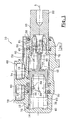
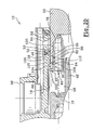
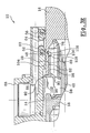
- FIG. 1 shows the assembly of a brake master cylinder 10 for a motor vehicle.
- the master cylinder 10 is a master cylinder of the "tandem" type which comprises a substantially axial body 12 of axis A within a bore 14 of which are slidably mounted two axial pistons 16 and 18.
- the piston 16, said primary piston 16, is intended to allow the establishment of a hydraulic pressure in a primary braking circuit of the vehicle (not shown), and the piston 18, said secondary piston 18, is intended to allow the establishment hydraulic pressure in a secondary braking circuit of the vehicle (not shown) which is independent of the vehicle's primary braking system.
- the primary piston 16 can be actuated directly by a driver of the vehicle.
- a rear end 20 of the primary piston 16 may be connected to a servomotor (not shown) which amplifies the forces exerted on a brake pedal of the vehicle.
- the secondary piston 18 can be actuated indirectly by the driver of the vehicle, in particular by the primary piston 16, as will be seen later.
- Each primary piston 16 or secondary 18 is thus movable between a rear rest position, which is shown in Figure 1, and a position before applying a braking force.
- each primary or secondary piston 16 is resiliently biased towards its rear rest position. It may optionally be resiliently biased towards its rear rest position against a stop (not shown).
- the secondary piston 18 is biased backwards by a spring 38 which bears on a front end transverse face 40 of the bore 14 and on the secondary piston 18, and the primary piston 16 is resiliently biased backwards. by a spring 42 which bears on a rear transverse face 44 of the secondary piston 18 and on the primary piston 16. More particularly, the spring 42 is mounted around a sliding cylinder 46 which is interposed between the rear transverse face 44 of the piston secondary 18 and the primary piston 16. The spring 42 is preloaded, to allow the primary piston 16 to push the secondary piston 18 when applying a braking force.
- the master cylinder comprises at least two means before primary sealing 48 and secondary 50 which are interposed respectively between the primary piston 16 and the bore 14, and between the secondary piston 18 and the bore 14.
- the primary and secondary sealing means are made by lip seals 48 and 50 which are received in grooves 52 and 54 of the body 12 respectively rearward of shoulders 28 and 36 of the bore 14.
- Each seal 48, 50 comprises at least one lip which is in contact with the periphery of the associated piston 16,18.
- seals 48, 50 could be received in cylindrical housings reported in the body of the master cylinder, said housings comprising all or part of the grooves 52, 54 in which are received the joints 48, 50.
- the primary sealing means 48 delimits in the bore 14 a rear primary supply chamber 56 and a front pressure primary chamber 58.
- the secondary sealing means 50 delimits in the bore 14 a rear secondary supply chamber 60 and a secondary front pressure chamber 62.
- the body 12 comprises a radial primary supply duct 64 which connects a primary external reservoir (not shown) of hydraulic fluid to the rear primary supply chamber 56.
- the radial primary conduit 64 is for example connected via an intermediate longitudinal conduit 66 to an orifice 68 which opens outwardly from the body 12 and which is intended to receive an outlet mouth (not shown) of the associated primary reservoir.
- the body 12 comprises a radial secondary supply duct 70 which connects a secondary external reservoir (not shown) of hydraulic fluid to the rear secondary supply chamber 60.
- the duct 70 opens out of the body 12 through through an orifice 72 which is intended to receive an outlet mouth (not shown) of the associated secondary reservoir.
- the body 12 has two primary and secondary holes 76 76 which respectively open on the one hand in the primary pressure chamber 58 and secondary 62 and secondly outside the body 12 to supply associated braking circuits (not shown ) primary and secondary.
- each piston 16, 18 comprises a bore. 78, 80 which is open towards the front, whose rear end is closed by a transverse bottom wall, and which communicates with the front pressure chamber 58, 62.
- Each piston 16, 18 comprises at least one valve 82, 84 which is arranged between the rear feed chamber 56, 60 and the bore 78, 80 of the piston 16, 18.
- Each valve 82, 84 includes, by way of example and in a nonlimiting manner of the invention, at least one radial bore 86, 88, arranged between the bore 78, 80 of each piston 16, 18 and its periphery, of which the position relative to the lip seal 48, 50 allows or not the passage of the hydraulic fluid from the rear supply chamber 56, 60 to the front pressure chamber 58, 62.
- each valve 82, 84 comprises a plurality of bores 86, 88 which are angularly arranged in a regular manner around the periphery of the piston 16, 18.
- each valve 82, 84 is movable between an open position, shown in Figure 1, in which, when one of the pistons 16, 18 is in its rear rest position, it puts in communication the rear supply chamber 56 or 60 of said piston 16, 18 with the front pressure chamber 58 or 62 of said piston 16, 18, and a closed position (not shown) in which, when the piston 16, 18 is moved axially forward towards its position d application, it isolates the associated front pressure chamber 58, 62 from the rear supply chamber 56, 60 associated and thus allows the establishment of a braking pressure in the front pressure chamber 58, 62.
- the closure of the primary valve 82 is subject to the path, by the primary piston 16, a stroke "Cm 1 " called “dead stroke", which corresponds to the distance between the hole 86 of the attached 48.
- the bore 86 remains behind the lip seal 48 and allows the passage of hydraulic fluid between the rear primary supply chamber 56 and the chamber front pressure primer 58.
- the valve 82 is open.
- a rear wall 53 of the groove 52 is of a minimum thickness to ensure proper retention of the seal 48 in its groove 52.
- the bore 86 must, in the rest position of the piston 16, be arranged substantially facing the supply duct 64 so as to allow an optimal supply of the valve 82 in hydraulic fluid.
- a master cylinder 10 of the type described above comprising at least one tubular cylindrical element 90 inside the piston 16 which is arranged in the primary pressure chamber 58 before, which extends axially behind the sealing means 48 and which is intended, during the advance of the primary piston 16, to close the radial valve 82 to obtain a race dead "Cm 2 " closing the valve 82 which is less than the distance between the valve 82 of the sealing means 48. It is also known to provide a similar configuration for the secondary piston 18.
- Such an element 90 is generally free to slide in the bore 14 and is elastically biased against a shoulder face of the bore. It is therefore particularly bulky and the construction of a master cylinder 10 comprising such a member 90 is therefore particularly expensive.
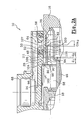
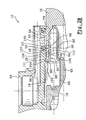
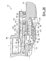
- FIGS. 2A to 2E Two embodiments of a master cylinder 10 comprising such a tubular cylindrical element 90 have been shown in particular on the one hand with reference to FIGS. 2A to 2E and on the other hand with reference to FIGS. 3A to 3E.
- the tubular cylindrical element 90 is arranged radially at least partly inside the bore 78 of the piston.
- tubular cylindrical element 90 comprises a tubular front section 96, which extends axially forward of the sealing means 48 and which comprises the first removable means 92 for connection with the bore 14 of the body 12 of the master cylinder 10.
- the tubular cylindrical element 90 also comprises a tubular rear section 98, whose outside diameter is the diameter of the bore 78 of the piston 16, and which extends axially behind the front section 96 of the tubular cylindrical element 90.
- the rear end 100 of the tubular rear section 98 is arranged behind the sealing means 48 and in front of the bore 86 of the piston 16 when in its rear rest position, as shown in FIGS. 2A and 3A.
- the tubular rear section 98 comprises the second removable means 94 connecting the piston 16.
- first removable means 92 for connection with the bore 14 of the tubular cylindrical element 90 comprise at least two first elastic radial tabs 102, which extend radially at regular intervals from the front section 96, and which are capable of locking / unlocking in a groove 104 of the bore 14 which is arranged in front of the sealing means 48.
- the second removable connecting means 94 comprise at least two elastic radial second tabs 106 which extend radially outwardly from the periphery of the rear section 98 of the tubular cylindrical element 90 and which are capable of locking / unlocking in a groove 107 of the bore 78 of the piston 16.
- the second elastic radial tabs 106 are arranged in front of the bore 86 forming the valve of the piston.
- each second elastic radial tab 106 is arranged perpendicularly to the end of a flexible longitudinal arm 108 housed in a longitudinal slot 110 of the periphery of the rear section 98 of the tubular cylindrical element 90.
- the distance "d 1 " separating the first elastic tabs 102 from the second elastic tabs 106 is equal to the distance "d 2 " separating the groove 107 from the bore 78 of the primary piston 16 from its front end 111.
- the primary piston 16 is movable between five remarkable positions.
- the dead stroke "Cm 2 " is reduced to the distance between the bore 86 of the piston 16 of the rear section 98 of the tubular element 90, as shown in FIG. 2A.
- the primary piston 16 occupies its rest position, as shown in FIG. 2A.
- the valve 82 is open because the holes 86 are arranged behind the rear section 98 of the tubular element 90.
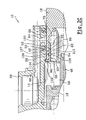
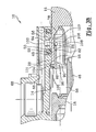
- the primary piston 16 comes into contact with the front section 92 of the tubular element 90.
- the second elastic radial tabs 106 are then received in the groove 107 of the bore 78 of the piston 16.
- the primary piston 16 pushes the front section 92 of the tubular element 90, which has the effect of driving the first elastic radial tabs 102 out of the groove 104 of the bore 14.
- the tubular element 90 thus accompanies the primary piston 16 over the entire end of its stroke, since it is locked to it by means of the second elastic tabs 106 which are received in the groove 107.
- the primary piston 16 can then return to its rest position shown in Figure 2A.
- the valve 82 is then opened again.
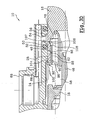
- the second elastic radial tabs 106 extend from the end 100 of the rear section 98 of the tubular element 90 and are arranged behind the bore 86, regardless of the position of the piston 16 and the rear portion 98 of the tubular element 90. This configuration improves the seal between the element 90 and the piston 16, and it simplifies the embodiment by molding of the tubular element 90.
- the distance “d 1 " separating the first elastic tabs 102 from the second elastic tabs 106 is equal to the distance “d 2 " separating the groove 107 from the bore 78 of the primary piston 16 from its front end 111.
- the primary piston 16 occupies its rest position, as shown in FIG. 3A.
- the valve 82 is open because the holes 86 are arranged behind the end 100 of the rear section 96 of the tubular element 90.
- the primary piston 16 comes into contact with the front section 92 of the tubular element 90.
- the second elastic radial tabs 106 are then received in the groove 107 of the bore 78 of the piston 16.
- the primary piston 16 pushes the front section 92 of the tubular element 90, which has the effect of driving the first elastic radial tabs 102 out of the groove 104 of the bore 14.
- the tubular element 90 thus accompanies the primary piston 16 over the entire end of its stroke, since it is locked to it by means of the second elastic tabs 106 which are received in the groove 107.
- the primary piston 16 can then return to its rest position shown in FIG. 3A.
- the valve 82 is then opened again.
- the invention thus provides a master cylinder 10 having a reduced application stroke, guaranteeing increased braking safety.
Landscapes
- Engineering & Computer Science (AREA)
- Transportation (AREA)
- Mechanical Engineering (AREA)
- Transmission Of Braking Force In Braking Systems (AREA)
- Vehicle Body Suspensions (AREA)
- Braking Arrangements (AREA)
- Braking Systems And Boosters (AREA)
- Manufacture Of Alloys Or Alloy Compounds (AREA)
Claims (11)
- Hydraulischer "Tandem"-Hauptbremszylinder (10) für ein Kraftfahrzeug, vom Typ, der einen im Wesentlichen axialen Körper (12) mit einer Bohrung (14) aufweist, in der von hinten nach vorne ein axialer Primärkolben (16) und ein axialer Sekundärkolben (18) gleitend angebracht sind, welche von einem Fahrer des Fahrzeugs zwischen einer hinteren Ruhestellung und einer vorderen Stellung zum Aufbringen einer Bremskraft betätigt werden können, vom Typ, bei dem jeder Kolben (16, 18) elastisch gegen einen ersten hinteren Anschlag in seine hintere Ruhestellung zurückgestellt wird, vom Typ, bei dem mindestens ein Dichtmittel (48, 50) zwischen jedem Kolben (16, 18) und der Bohrung (14) angeordnet ist, um in der Bohrung (14) eine hintere Kammer (56, 60) zur Versorgung mit Hydraulikfluid und eine vordere Druckkammer (58, 62) zu begrenzen, vom Typ, bei dem jeder Kolben (16, 18) eine Bohrung (78, 80) aufweist, die nach vorne offen ist und mit der vorderen Druckkammer (58, 62) in Verbindung steht, vom Typ, bei dem der Kolben (16, 18) mindestens ein im Wesentlichen radiales Ventilelement (82, 84) aufweist, das in seinen Umfang und in seine Bohrung (78, 80) mündet und zwischen einer der hinteren Ruhestellung des Kolbens (16, 18) entsprechenden Durchlassstellung, in der das Ventilelement (82, 84) hinter dem Dichtmittel (48, 50) angeordnet ist und die hintere Versorgungskammer (56, 60) mit der vorderen Druckkammer (58, 62) verbindet, und einer der vorderen Beaufschlagungsstellung des Kolbens (16, 18) entsprechenden Sperrstellung beweglich ist, in der das Ventilelement (82, 84) vor dem Dichtmittel (48, 50) angeordnet ist und die Verbindung zwischen der hinteren Versorgungskammer (56, 60) und der vorderen Druckkammer (58, 62) trennt, um den Aufbau eines hydraulischen Bremsdrucks in der vorderen Druckkammer (58, 62) zu ermöglichen, und vom Typ, bei dem die jedem Kolben (16, 18) zugeordnete vordere Druckkammer (58) mindestens ein zylindrisches, röhrenförmiges Element (90) aufweist, das im Kolben (16, 18) angeordnet ist, sich axial hinter dem Dichtmittel (48, 50) erstreckt und bei der Vorwärtsbewegung des Kolbens (16, 18) das radiale Ventilelement (82, 84) schließen soll, um einen Weg (Cm2) zum Schließen des unteren Ventilelements zu erhalten, der kleiner ist als der Abstand zwischen dem Ventilelement (82, 84) und dem Dichtmittel (48, 50),
dadurch gekennzeichnet, dass jedes zylindrische, röhrenförmige Element (90) folgendes aufweist:- erste abnehmbare Mittel (92) zur Verbindung mit der Bohrung (14) und- zweite abnehmbare Mittel (94) zur Verbindung mit dem zugeordneten Kolben (16),die es jeweils ermöglichen sollen, dass jeder Kolben (16, 18) bei seiner Vorwärtsbewegung das zugeordnete zylindrische, röhrenförmige Element (90) mitnimmt und es dann bei seiner Rückwärtsbewegung zurückstellt, damit es in der Bohrung (14) axial ein Minimum an Platz einnimmt. - Hauptzylinder (10) nach dem vorhergehenden Anspruch, dadurch gekennzeichnet, dass das zylindrische, röhrenförmige Element (90) radial zumindest teilweise in der Bohrung (78) des Kolbens (16) angeordnet ist.
- Hauptzylinder (10) nach einem der vorhergehenden Ansprüche, dadurch gekennzeichnet, dass der Kolben (16) einstückig ausgebildet ist, dass seine Bohrung (78) an ihrem hinteren Ende durch eine quer verlaufende Rückwand verschlossen ist und dass das radiale Ventilelement (82) mindestens eine Durchbohrung (86) aufweist, die in den Umfang und in die Bohrung (78) des Kolbens (16) mündet.
- Hauptzylinder (10) nach Anspruch 2 in Kombination mit Anspruch 3, dadurch gekennzeichnet, dass das zylindrische, röhrenförmige Element (90) folgendes aufweist:- einen vorderen röhrenförmigen Abschnitt (96), der sich axial vor dem Dichtmittel (48) erstreckt und die ersten abnehmbaren Mittel (92) zur Verbindung mit der Bohrung (14) des Körpers (12) des Hauptzylinders (10) aufweist,- einen hinteren röhrenförmigen Abschnitt (98), dessen Außendurchmesser dem Durchmesser der Bohrung (78) des Kolbens (16) entspricht, der sich axial hinter dem vorderen Abschnitt (96) des zylindrischen, röhrenförmigen Elements erstreckt, bei dem das hintere Ende (100) hinter dem Dichtmittel (48) und vor der Durchbohrung (86) des Kolbens (16) angeordnet ist, wenn er sich in seiner hinteren Ruhestellung befindet, und der die zweiten abnehmbaren Mittel (94) zur Verbindung mit dem Kolben (16) aufweist.
- Hauptzylinder (10) nach dem vorhergehenden Anspruch, dadurch gekennzeichnet, dass die ersten abnehmbaren Mittel (92) zur Verbindung mit der Bohrung (14) des zylindrischen, röhrenförmigen Elements (90) mindestens zwei erste radiale, elastische Laschen (102) aufweisen, die sich ausgehend von dem vorderen Abschnitt (96) radial in gleichmäßigen Abständen erstrecken und in eine vor dem Dichtmittel (48) angeordnete Nut (104) der Bohrung (14) einrasten und sich aus dieser lösen können.
- Hauptzylinder (10) nach Anspruch 4 oder 5, dadurch gekennzeichnet, dass die zweiten abnehmbaren Verbindungsmittel (94) mindestens zwei zweite radiale, elastische Laschen (106) aufweisen, die sich ausgehend von dem Umfang des hinteren Abschnitts (98) des zylindrischen, röhrenförmigen Elements (90) radial nach außen erstrecken und in eine Nut (107) der Bohrung (78) des Kolbens (16) einrasten und sich aus dieser lösen können.
- Hauptzylinder (10) nach dem vorhergehenden Anspruch, dadurch gekennzeichnet, dass jede von den zweiten radialen, elastischen Laschen (106) senkrecht zum Ende eines flexiblen Längsarms (108) angeordnet ist, der in einer Längsöffnung (110) des Umfangs des hinteren Abschnitts (98) des zylindrischen, röhrenförmigen Elements (90) aufgenommen ist.
- Hauptzylinder (10) nach Anspruch 6 oder 7, dadurch gekennzeichnet, dass die zweiten radialen, elastischen Laschen (106) vor der Bohrung (86) angeordnet sind, die das Ventilelement (82) des Kolbens (16) bildet.
- Hauptzylinder (10) nach Anspruch 6, dadurch gekennzeichnet, dass sich die zweiten radialen, elastischen Laschen (106) ausgehend von dem Ende (100) des hinteren Abschnitts (98) des röhrenförmigen Elements (90) erstrecken und hinter der Bohrung (86) angeordnet sind, die das Ventilelement (82) des Kolbens (16) bildet.
- Hauptzylinder (10) nach einem der Ansprüche 6 bis 9, dadurch gekennzeichnet, dass der Abstand (d1) zwischen den ersten elastischen Laschen (102) und den zweiten elastischen Laschen (106) dem Abstand (d2) zwischen der Nut (107) der Bohrung (78) des Primärkolbens (16) und dessen vorderem Ende entspricht.
- Hauptzylinder (10) nach einem der vorhergehenden Ansprüche, dadurch gekennzeichnet, dass das Dichtmittel (48, 50) aus einer Lippendichtung besteht, die in einer Nut (52, 54) der Bohrung (14) des Hauptzylinders (10) aufgenommen ist.
Applications Claiming Priority (3)
| Application Number | Priority Date | Filing Date | Title |
|---|---|---|---|
| FR0214779A FR2847538B1 (fr) | 2002-11-22 | 2002-11-22 | Maitre-cylindre a course d'application reduite |
| FR0214779 | 2002-11-22 | ||
| PCT/EP2003/012748 WO2004048175A1 (fr) | 2002-11-22 | 2003-11-14 | Maitre-cylindre a course d'application reduite |
Publications (2)
| Publication Number | Publication Date |
|---|---|
| EP1565366A1 EP1565366A1 (de) | 2005-08-24 |
| EP1565366B1 true EP1565366B1 (de) | 2007-01-24 |
Family
ID=32241593
Family Applications (1)
| Application Number | Title | Priority Date | Filing Date |
|---|---|---|---|
| EP03795819A Expired - Lifetime EP1565366B1 (de) | 2002-11-22 | 2003-11-14 | Hauptbremszylinder mit kurzem betätigunsweg |
Country Status (6)
| Country | Link |
|---|---|
| EP (1) | EP1565366B1 (de) |
| AT (1) | ATE352463T1 (de) |
| AU (1) | AU2003298114A1 (de) |
| DE (1) | DE60311515D1 (de) |
| FR (1) | FR2847538B1 (de) |
| WO (1) | WO2004048175A1 (de) |
Families Citing this family (1)
| Publication number | Priority date | Publication date | Assignee | Title |
|---|---|---|---|---|
| CN114810874B (zh) * | 2022-05-13 | 2024-04-26 | 浙江奔腾智能制动系统有限公司 | 一种适用于拖拉机单腔结构的柱塞式的制动主缸 |
Family Cites Families (4)
| Publication number | Priority date | Publication date | Assignee | Title |
|---|---|---|---|---|
| JPH0217203A (ja) * | 1988-07-05 | 1990-01-22 | Jidosha Kiki Co Ltd | 流体アクチュエータ |
| JP2898388B2 (ja) * | 1990-09-28 | 1999-05-31 | 自動車機器株式会社 | タンデム型マスタシリンダ |
| DE19537038B4 (de) * | 1995-10-05 | 2006-05-24 | Stephan Thies | Geberzylinder |
| JP2002255020A (ja) * | 2001-02-27 | 2002-09-11 | Aisin Seiki Co Ltd | マスターシリンダ |
-
2002
- 2002-11-22 FR FR0214779A patent/FR2847538B1/fr not_active Expired - Fee Related
-
2003
- 2003-11-14 AU AU2003298114A patent/AU2003298114A1/en not_active Abandoned
- 2003-11-14 DE DE60311515T patent/DE60311515D1/de not_active Expired - Lifetime
- 2003-11-14 WO PCT/EP2003/012748 patent/WO2004048175A1/fr not_active Ceased
- 2003-11-14 EP EP03795819A patent/EP1565366B1/de not_active Expired - Lifetime
- 2003-11-14 AT AT03795819T patent/ATE352463T1/de not_active IP Right Cessation
Also Published As
| Publication number | Publication date |
|---|---|
| DE60311515D1 (de) | 2007-03-15 |
| FR2847538B1 (fr) | 2005-02-25 |
| ATE352463T1 (de) | 2007-02-15 |
| EP1565366A1 (de) | 2005-08-24 |
| AU2003298114A1 (en) | 2004-06-18 |
| WO2004048175A1 (fr) | 2004-06-10 |
| FR2847538A1 (fr) | 2004-05-28 |
Similar Documents
| Publication | Publication Date | Title |
|---|---|---|
| EP1995138B1 (de) | Hauptbremszylinder, der eine Fuge zum leichteren Nachfüllen der Bremse umfasst | |
| EP1995139B1 (de) | Hauptbremszylinder, der eine Fuge und eine entsprechende Hohlkehle zum leichteren Nachfüllen der Bremse umfasst | |
| EP1360100A1 (de) | Hauptzylinder mit erholungsdichtung | |
| EP1636077B1 (de) | Servomotor mit verringertem totgang und solch einen servomotor umfassendes bremssystem | |
| EP0162772A2 (de) | Hydraulischer Druckerzeuger | |
| EP1427621B1 (de) | Hauptbremszylinder mit verkürztem ventil-todweg | |
| FR2751602A1 (fr) | Dispositif de freinage assiste a rapport d'assistance variable | |
| FR2836842A1 (fr) | Dispositif a gicleur telescopique | |
| EP1995137B1 (de) | Hauptbremszylinder, der eine Spiralnut zum Nachfüllen der Bremse umfasst | |
| EP0779868B1 (de) | Bremsanlage mit erhöhter sicherheit | |
| EP1360099A1 (de) | Hauptzylinder mit erholungsrillen | |
| EP0779870B1 (de) | Pneumatischer bremskraftverstärker | |
| EP1565366B1 (de) | Hauptbremszylinder mit kurzem betätigunsweg | |
| FR2586983A1 (fr) | Systeme de freinage a regulation du glissement | |
| FR2809066A1 (fr) | Servomoteur comportant un embrayage unidirectionnel expansible | |
| EP1054174A2 (de) | Hydraulischer Kupplungsausrückzylinder | |
| EP1350702A1 (de) | Hauptbremszylinder mit reduzierter Geräuschentwicklung | |
| EP0041885B1 (de) | Hydraulischer Bremskraftverstärker | |
| FR2844238A1 (fr) | Servofrein comportant un maitre-cylindre a reaction reduite | |
| FR2822427A1 (fr) | Servomoteur d'assistance a ecoulement simplifie | |
| EP0368701B2 (de) | Hydraulische Servobremsanlage und Bremskraftverstärker und Regelventil für eine solche Anlage | |
| FR2729356A1 (fr) | Servomoteur pneumatique d'assistance au freinage a clapet souple | |
| FR3104096A1 (fr) | Maître-cylindre pour un système de freinage | |
| EP1693264A1 (de) | Pneumatischer Bremskraftverstärker mit reduziertem Todweg und Hauptbremszylinder für einen solchen Verstärker | |
| EP1423303A1 (de) | Einen integrierten hauptzylinderbremskraftverstärker verwendende bremsvorrichtung |
Legal Events
| Date | Code | Title | Description |
|---|---|---|---|
| PUAI | Public reference made under article 153(3) epc to a published international application that has entered the european phase |
Free format text: ORIGINAL CODE: 0009012 |
|
| 17P | Request for examination filed |
Effective date: 20050622 |
|
| AK | Designated contracting states |
Kind code of ref document: A1 Designated state(s): AT BE BG CH CY CZ DE DK EE ES FI FR GB GR HU IE IT LI LU MC NL PT RO SE SI SK TR |
|
| AX | Request for extension of the european patent |
Extension state: AL LT LV MK |
|
| DAX | Request for extension of the european patent (deleted) | ||
| GRAP | Despatch of communication of intention to grant a patent |
Free format text: ORIGINAL CODE: EPIDOSNIGR1 |
|
| GRAS | Grant fee paid |
Free format text: ORIGINAL CODE: EPIDOSNIGR3 |
|
| GRAA | (expected) grant |
Free format text: ORIGINAL CODE: 0009210 |
|
| AK | Designated contracting states |
Kind code of ref document: B1 Designated state(s): AT BE BG CH CY CZ DE DK EE ES FI FR GB GR HU IE IT LI LU MC NL PT RO SE SI SK TR |
|
| PG25 | Lapsed in a contracting state [announced via postgrant information from national office to epo] |
Ref country code: IE Free format text: LAPSE BECAUSE OF FAILURE TO SUBMIT A TRANSLATION OF THE DESCRIPTION OR TO PAY THE FEE WITHIN THE PRESCRIBED TIME-LIMIT Effective date: 20070124 Ref country code: FI Free format text: LAPSE BECAUSE OF FAILURE TO SUBMIT A TRANSLATION OF THE DESCRIPTION OR TO PAY THE FEE WITHIN THE PRESCRIBED TIME-LIMIT Effective date: 20070124 Ref country code: DK Free format text: LAPSE BECAUSE OF FAILURE TO SUBMIT A TRANSLATION OF THE DESCRIPTION OR TO PAY THE FEE WITHIN THE PRESCRIBED TIME-LIMIT Effective date: 20070124 Ref country code: AT Free format text: LAPSE BECAUSE OF FAILURE TO SUBMIT A TRANSLATION OF THE DESCRIPTION OR TO PAY THE FEE WITHIN THE PRESCRIBED TIME-LIMIT Effective date: 20070124 Ref country code: NL Free format text: LAPSE BECAUSE OF FAILURE TO SUBMIT A TRANSLATION OF THE DESCRIPTION OR TO PAY THE FEE WITHIN THE PRESCRIBED TIME-LIMIT Effective date: 20070124 Ref country code: SI Free format text: LAPSE BECAUSE OF FAILURE TO SUBMIT A TRANSLATION OF THE DESCRIPTION OR TO PAY THE FEE WITHIN THE PRESCRIBED TIME-LIMIT Effective date: 20070124 |
|
| REG | Reference to a national code |
Ref country code: GB Ref legal event code: FG4D Free format text: NOT ENGLISH |
|
| REG | Reference to a national code |
Ref country code: CH Ref legal event code: EP |
|
| REG | Reference to a national code |
Ref country code: IE Ref legal event code: FG4D Free format text: LANGUAGE OF EP DOCUMENT: FRENCH |
|
| REF | Corresponds to: |
Ref document number: 60311515 Country of ref document: DE Date of ref document: 20070315 Kind code of ref document: P |
|
| PG25 | Lapsed in a contracting state [announced via postgrant information from national office to epo] |
Ref country code: SE Free format text: LAPSE BECAUSE OF FAILURE TO SUBMIT A TRANSLATION OF THE DESCRIPTION OR TO PAY THE FEE WITHIN THE PRESCRIBED TIME-LIMIT Effective date: 20070424 |
|
| PG25 | Lapsed in a contracting state [announced via postgrant information from national office to epo] |
Ref country code: BG Free format text: LAPSE BECAUSE OF EXPIRATION OF PROTECTION Effective date: 20070425 |
|
| PG25 | Lapsed in a contracting state [announced via postgrant information from national office to epo] |
Ref country code: ES Free format text: LAPSE BECAUSE OF FAILURE TO SUBMIT A TRANSLATION OF THE DESCRIPTION OR TO PAY THE FEE WITHIN THE PRESCRIBED TIME-LIMIT Effective date: 20070505 |
|
| PG25 | Lapsed in a contracting state [announced via postgrant information from national office to epo] |
Ref country code: PT Free format text: LAPSE BECAUSE OF FAILURE TO SUBMIT A TRANSLATION OF THE DESCRIPTION OR TO PAY THE FEE WITHIN THE PRESCRIBED TIME-LIMIT Effective date: 20070625 |
|
| NLV1 | Nl: lapsed or annulled due to failure to fulfill the requirements of art. 29p and 29m of the patents act | ||
| GBV | Gb: ep patent (uk) treated as always having been void in accordance with gb section 77(7)/1977 [no translation filed] |
Effective date: 20070124 |
|
| REG | Reference to a national code |
Ref country code: IE Ref legal event code: FD4D |
|
| PG25 | Lapsed in a contracting state [announced via postgrant information from national office to epo] |
Ref country code: GB Free format text: LAPSE BECAUSE OF FAILURE TO SUBMIT A TRANSLATION OF THE DESCRIPTION OR TO PAY THE FEE WITHIN THE PRESCRIBED TIME-LIMIT Effective date: 20070124 Ref country code: SK Free format text: LAPSE BECAUSE OF FAILURE TO SUBMIT A TRANSLATION OF THE DESCRIPTION OR TO PAY THE FEE WITHIN THE PRESCRIBED TIME-LIMIT Effective date: 20070124 |
|
| PLBE | No opposition filed within time limit |
Free format text: ORIGINAL CODE: 0009261 |
|
| STAA | Information on the status of an ep patent application or granted ep patent |
Free format text: STATUS: NO OPPOSITION FILED WITHIN TIME LIMIT |
|
| 26N | No opposition filed |
Effective date: 20071025 |
|
| PG25 | Lapsed in a contracting state [announced via postgrant information from national office to epo] |
Ref country code: RO Free format text: LAPSE BECAUSE OF FAILURE TO SUBMIT A TRANSLATION OF THE DESCRIPTION OR TO PAY THE FEE WITHIN THE PRESCRIBED TIME-LIMIT Effective date: 20070124 Ref country code: CZ Free format text: LAPSE BECAUSE OF FAILURE TO SUBMIT A TRANSLATION OF THE DESCRIPTION OR TO PAY THE FEE WITHIN THE PRESCRIBED TIME-LIMIT Effective date: 20070124 |
|
| PG25 | Lapsed in a contracting state [announced via postgrant information from national office to epo] |
Ref country code: DE Free format text: LAPSE BECAUSE OF FAILURE TO SUBMIT A TRANSLATION OF THE DESCRIPTION OR TO PAY THE FEE WITHIN THE PRESCRIBED TIME-LIMIT Effective date: 20070425 |
|
| PG25 | Lapsed in a contracting state [announced via postgrant information from national office to epo] |
Ref country code: IT Free format text: LAPSE BECAUSE OF FAILURE TO SUBMIT A TRANSLATION OF THE DESCRIPTION OR TO PAY THE FEE WITHIN THE PRESCRIBED TIME-LIMIT Effective date: 20070124 Ref country code: GR Free format text: LAPSE BECAUSE OF FAILURE TO SUBMIT A TRANSLATION OF THE DESCRIPTION OR TO PAY THE FEE WITHIN THE PRESCRIBED TIME-LIMIT Effective date: 20070425 |
|
| BERE | Be: lapsed |
Owner name: ROBERT BOSCH G.M.B.H. Effective date: 20071130 |
|
| PG25 | Lapsed in a contracting state [announced via postgrant information from national office to epo] |
Ref country code: MC Free format text: LAPSE BECAUSE OF NON-PAYMENT OF DUE FEES Effective date: 20071130 |
|
| PG25 | Lapsed in a contracting state [announced via postgrant information from national office to epo] |
Ref country code: CH Free format text: LAPSE BECAUSE OF NON-PAYMENT OF DUE FEES Effective date: 20071130 Ref country code: LI Free format text: LAPSE BECAUSE OF NON-PAYMENT OF DUE FEES Effective date: 20071130 |
|
| REG | Reference to a national code |
Ref country code: CH Ref legal event code: PL |
|
| PG25 | Lapsed in a contracting state [announced via postgrant information from national office to epo] |
Ref country code: BE Free format text: LAPSE BECAUSE OF NON-PAYMENT OF DUE FEES Effective date: 20071130 |
|
| PG25 | Lapsed in a contracting state [announced via postgrant information from national office to epo] |
Ref country code: EE Free format text: LAPSE BECAUSE OF FAILURE TO SUBMIT A TRANSLATION OF THE DESCRIPTION OR TO PAY THE FEE WITHIN THE PRESCRIBED TIME-LIMIT Effective date: 20070124 |
|
| PG25 | Lapsed in a contracting state [announced via postgrant information from national office to epo] |
Ref country code: CY Free format text: LAPSE BECAUSE OF FAILURE TO SUBMIT A TRANSLATION OF THE DESCRIPTION OR TO PAY THE FEE WITHIN THE PRESCRIBED TIME-LIMIT Effective date: 20070124 |
|
| PG25 | Lapsed in a contracting state [announced via postgrant information from national office to epo] |
Ref country code: LU Free format text: LAPSE BECAUSE OF NON-PAYMENT OF DUE FEES Effective date: 20071114 |
|
| PG25 | Lapsed in a contracting state [announced via postgrant information from national office to epo] |
Ref country code: HU Free format text: LAPSE BECAUSE OF FAILURE TO SUBMIT A TRANSLATION OF THE DESCRIPTION OR TO PAY THE FEE WITHIN THE PRESCRIBED TIME-LIMIT Effective date: 20070725 Ref country code: TR Free format text: LAPSE BECAUSE OF FAILURE TO SUBMIT A TRANSLATION OF THE DESCRIPTION OR TO PAY THE FEE WITHIN THE PRESCRIBED TIME-LIMIT Effective date: 20070124 |
|
| REG | Reference to a national code |
Ref country code: FR Ref legal event code: PLFP Year of fee payment: 13 |
|
| REG | Reference to a national code |
Ref country code: FR Ref legal event code: PLFP Year of fee payment: 14 |
|
| PGFP | Annual fee paid to national office [announced via postgrant information from national office to epo] |
Ref country code: FR Payment date: 20161124 Year of fee payment: 14 |
|
| REG | Reference to a national code |
Ref country code: FR Ref legal event code: ST Effective date: 20180731 |
|
| PG25 | Lapsed in a contracting state [announced via postgrant information from national office to epo] |
Ref country code: FR Free format text: LAPSE BECAUSE OF NON-PAYMENT OF DUE FEES Effective date: 20171130 |