EP1564842B1 - Ultrabreitbandige Antenne - Google Patents
Ultrabreitbandige Antenne Download PDFInfo
- Publication number
- EP1564842B1 EP1564842B1 EP04290421.9A EP04290421A EP1564842B1 EP 1564842 B1 EP1564842 B1 EP 1564842B1 EP 04290421 A EP04290421 A EP 04290421A EP 1564842 B1 EP1564842 B1 EP 1564842B1
- Authority
- EP
- European Patent Office
- Prior art keywords
- ground plane
- monopole
- antenna according
- plane
- border
- Prior art date
- Legal status (The legal status is an assumption and is not a legal conclusion. Google has not performed a legal analysis and makes no representation as to the accuracy of the status listed.)
- Expired - Lifetime
Links
Images




Classifications
-
- H—ELECTRICITY
- H01—ELECTRIC ELEMENTS
- H01Q—ANTENNAS, i.e. RADIO AERIALS
- H01Q1/00—Details of, or arrangements associated with, antennas
- H01Q1/12—Supports; Mounting means
- H01Q1/22—Supports; Mounting means by structural association with other equipment or articles
- H01Q1/24—Supports; Mounting means by structural association with other equipment or articles with receiving set
- H01Q1/241—Supports; Mounting means by structural association with other equipment or articles with receiving set used in mobile communications, e.g. GSM
-
- H—ELECTRICITY
- H01—ELECTRIC ELEMENTS
- H01Q—ANTENNAS, i.e. RADIO AERIALS
- H01Q1/00—Details of, or arrangements associated with, antennas
- H01Q1/36—Structural form of radiating elements, e.g. cone, spiral, umbrella; Particular materials used therewith
- H01Q1/38—Structural form of radiating elements, e.g. cone, spiral, umbrella; Particular materials used therewith formed by a conductive layer on an insulating support
-
- H—ELECTRICITY
- H01—ELECTRIC ELEMENTS
- H01Q—ANTENNAS, i.e. RADIO AERIALS
- H01Q21/00—Antenna arrays or systems
- H01Q21/24—Combinations of antenna units polarised in different directions for transmitting or receiving circularly and elliptically polarised waves or waves linearly polarised in any direction
-
- H—ELECTRICITY
- H01—ELECTRIC ELEMENTS
- H01Q—ANTENNAS, i.e. RADIO AERIALS
- H01Q21/00—Antenna arrays or systems
- H01Q21/28—Combinations of substantially independent non-interacting antenna units or systems
-
- H—ELECTRICITY
- H01—ELECTRIC ELEMENTS
- H01Q—ANTENNAS, i.e. RADIO AERIALS
- H01Q9/00—Electrically-short antennas having dimensions not more than twice the operating wavelength and consisting of conductive active radiating elements
- H01Q9/04—Resonant antennas
- H01Q9/30—Resonant antennas with feed to end of elongated active element, e.g. unipole
- H01Q9/40—Element having extended radiating surface
Definitions
- the present invention relates to the field of antennas.
- the present invention relates to the field of antennas intended for broadcasting high-speed services, in particular in the UWB (Ultra Wide Band or Ultra Wide Band) domain, but also for wireless networks, such as WLAN (Wireless Lan). and WIFI (registered trademark) (Wireless Fidelity), as well as in the field of multiband cellular telecommunications.
- UWB Ultra Wide Band or Ultra Wide Band
- WLAN Wireless Lan
- WIFI registered trademark
- UWB A new system, called UWB, which allows the reuse of frequency bands already allocated for other applications is being developed for civil telecommunication applications.
- the UWB transmits at a very low level (of the order of noise) a coherent signal but spread over a very wide band of frequencies (hence the name "Ultra Wide Band”). Coherence is ensured by Gaussian pulse coding and it is essential that each element of the transmission chain, including the antenna, has the most neutral transfer function possible over the entire width of the band (typically 3 at 10 GHz) so that the receiving system is able to recover the useful signal in the middle of the noise.
- the antenna behaves like a band pass filter which conditions the performance of the complete system.
- the document DE 197 29 664 A describes antennas where the edge of the ground plane is convex towards the monopoly.
- the inventors have not identified, to date, known solutions that reconcile compact uniplanar structure and Ultra Wide Band performance (Fmax / Fmin> 5).
- the main object of the present invention is to remedy this situation by proposing a new antenna that makes it possible to meet these specifications, that is to say an antenna capable of transforming the incident energy into radiated energy over a very wide range.
- frequency band (Fmax / Fmin> 5).
- Another auxiliary object of the present invention is to provide an antenna whose geometry remains small vis-à-vis the wavelength.
- Yet another auxiliary object of the present invention is to provide an antenna that can easily be integrated on a PCMCIA or PCB type circuit board (ie Printed Circuit Board), for example in the form of a structure. coplanar etched on one side of an electronic substrate, facilitating the subsequent integration of active elements.
- PCMCIA or PCB type circuit board ie Printed Circuit Board
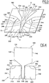
- an antenna comprising a support 10 of dielectric material which carries a monopole 100 and a ground plane 200.
- the support 10 may be made of any suitable material and may have any suitable geometry and dimensions.
- It is preferably of rectangular or square contour.
- the monopoly 100 and the ground plane 200 are coplanar. They are made in printed technology and by engraving on the same face of the support 10.
- the support 10 has dimensions of the order of 57.5 mm ⁇ 47 mm and a thickness of about 1.5 mm.
- the monopole 100 and the ground plane 200 have a symmetry with respect to a plane OO.
- This plane OO passes through the central axis of an excitation line 110.
- the excitation line 110 is formed of a rectilinear ribbon 112 of constant width delimited by two lateral edges 114, 115 parallel to each other and parallel to the plane O-O.
- the excitation line 110 thus extends, from the middle of one of the edges of the wafer, perpendicularly to this edge, toward the center of the support 10.
- the monopole 100 is connected to the inner end of the excitation line 110. It has a general shape flared away from the ground plane 200.
- the contour of the monopole 100 directed towards the ground plane 200 may have a continuous curvature. However, preferably this contour is delimited by a series of successive rectilinear sections whose inclination with respect to the plane OO increases away from the ground plane 200.
- the monopoly 100 can thus be delimited by three sections successive 120, 122 and 124 having respective inclinations of the order of 10 °, 30 ° and 45 ° and respective lengths of the order of 17 mm, 7 mm and 20 mm.
- the monopoly 100 is also limited, opposite the excitation line 110, by a straight edge 130, transverse to the plane OO, for example a length of the order of 37 mm.
- Monopoly 100 thus formed has the general shape of a planar cone with multiple slopes.
- the ground plane 200 comprises two blocks 210, 220 located respectively on either side of the feed line 110, being separated therefrom.
- the ground plane 200 has a border 230 directed towards the monopole 100 which is not completely rectilinear.
- the curvature of this border 230 may be continuous. However according to the embodiment illustrated on the figure 3 , this border 230 is delimited by a series of successive rectilinear sections.
- each block 210, 220 is delimited, starting from the edge of the support 10 on which the feed line 110 opens, by a rectilinear internal section 240, parallel to the plane OO, of the same length as the feed line 110, and by a rectilinear outer portion 242, also parallel to the plane OO, of a length greater than the section 240, typically of the order of twice the latter, for example of the order of 23.5mm.
- the two sections 240, 242 are connected by a plurality of sections 244, 246, 247, 248, which in combination define a convex shape, for each block, in the direction of the monopole 100. More precisely according to the particular and nonlimiting embodiment illustrated on the figure 3 the section 244 extends the section 242 and converges towards the plane OO in the direction of the monopole 100.
- the three sections 246, 247 and 248 follow each other from the internal section 240. They diverge, with progressively increasing angles, with respect to the plane. OO, close to the monopoly 100.
- the sections 244 and 248 meet at a point 249 which is the point of the ground plane 200 farthest from the edge of the support 10 on which the feed line 110 opens.
- the overall width of the ground plane 200, considered perpendicular to the plane OO, is substantially identical to the largest width of the monopole 100, at the edge 130.
- tip 249 of the ground plane 200 is located substantially opposite the outer quarter of the width of the expansion of the monopoly 100.
- the geometry of the ground plane 200 and that of the monopole 100 are preferably adapted such that the monopole defines an impedance at least substantially constant along its profile.
- the monopole 100, the feed line 110 and the ground plane 200 are advantageously made in printed circuit technology.
- the geometry of the ground plane 200 and that of the monopole 100 are adapted to reduce as much as possible the sizes and to optimize the shapes of the ground plane 200 as well as that of the coplanar monopole 100, so as to guarantee excitation by a line 110 coplanar characteristic impedance typical of telecommunications applications (ie in the range 50 Q - 70 ⁇ ) over the largest possible bandwidth.
- the monopoly 100 of polygonal shape, is asymmetrical with respect to the plane OO, while the ground plane 200 remains symmetrical with respect to this plane OO.
- the monopoly 100 is delimited, starting from the feed line 110, by two rectilinear sections 140, 142 diverging with respect to the plane OO away from the ground plane 200, at different angles, two parallel sections 144, 146 between they and parallel to the plane OO which respectively extend the two sections 140, 142, and the aforementioned end edge 130.
- Each block 210, 220 of the ground plane 200 is itself delimited by an internal generator 240, an external generator 242 , parallel to each other and parallel to the plane OO (the internal generator 240 having a length substantially identical to the feed line 110), an end section 250 rectilinear and perpendicular to the plane OO, connected to the internal generator 240 and two straight sections successive 252 and 254, which connect the end portion 250 and the external generator 242, which sections 252 and 254 diverge relative to the monopole 100 away from the plane OO
- the outer sections 242 are shorter than the inner sections 240.
- the sections 250, 252 and 254 define in combination a convex shape in the direction of the monopole 100.
- the overall width of the ground plane 200, considered perpendicular to the plane OO is greater than the width of the monopoly 100.
- the figure 5 represents an antenna variant that differs from that shown on the figure 4 by the fact that according to the figure 5 each inclined section 140, 142 of the monopole 100 is itself divided into two sections 1400, 1402 and 1420, 1422.
- the directed edge of the ground plane directed towards the monopole defines a concave, and not convex, edge in the direction of the monopole 100.
- This concave edge is defined by a section 250 perpendicular to the plane OO, connected to the internal section 240 and extended by two auxiliary sections 256, 258 to the outer section 242.
- the first section 256 diverges with respect to the plane OO in the direction of the monopole 100.
- the second section 258 is perpendicular to the plane OO and joins the outer section 242.
- each block 210, 220 of the ground plane 200 is provided with three rectilinear grooves 262, 263 and 264, parallel to each other and perpendicular to the plane O0, which open on the outer section 242.
- the grooves 260 are equidistant two by two. Their length decreases in approximation of the monopoly 100.
- Such grooves 260 make it possible to lower the minimum operating frequency of the structure, which increases the compactness for a given frequency band. They also stop the electric currents that would tend to "leak" behind the ground plane 200 causing parasitic radiation or parasitic coupling with the power supply.
- monopoly 100 comprises grooves 160. More precisely according to the particular and nonlimiting embodiment illustrated in FIG. figure 9 , the monopole 100 is provided with three straight grooves 162, 163 and 164, parallel to each other and perpendicular to the plane OO, which open on the outer sections 144, 146. According to the figure 9 the grooves 160 are equidistant two by two. Their length increases in approximation of the ground plane 200.
- Such grooves 160 also make it possible to lower the minimum operating frequency of the structure.
- a short-circuit 170 connects the monopole 100 and the ground plane 200.
- the short-circuit 170 is here formed of a rectilinear ribbon parallel to the plane OO, which connects the section 142 and the section 250 .
- FIG 11 another variant embodiment, according to the present invention, which differs from the figure 6 by the presence of slot lines 174, 178 in the monopole 100 and slot lines 274, 278 in the ground plane 200.
- the slotted lines 174, 178 open onto the sections 144.
- the slot line 174 comprises a rectilinear section 175 perpendicular to the plane OO, which opens on a section 144, a rectilinear section 176 parallel to the plane OO and a rectilinear section 177 perpendicular to the plane OO, of length less than section 175.
- the three sections 175, 176 and 177 generally define a U-shaped configuration.
- the slotted line 178 comprises a rectilinear section 179 perpendicular to the plane OO, which opens on the second section 144, and a rectilinear section 180 parallel to the plane OO, directed towards the section 130.
- the two sections 179 and 180 generally define an L-shaped configuration.
- the slot lines 274, 278 provided in the ground plane 200 have a geometry similar to that of the slot lines 174, 178 provided in the monopoly 100.
- the slit line 274 comprises a rectilinear section 275 perpendicular to the plane OO, which opens onto a section 242, a rectilinear section 276 parallel to the plane OO and a rectilinear section 277 perpendicular to the plane OO, of length less than section 275.
- the three sections 275, 276 and 277 generally define a U-shaped configuration.
- the slit line 278 comprises a rectilinear section 279 perpendicular to the plane OO, which opens on the second section 242, and a rectilinear section 280 parallel to the plane OO, directed towards the monopole 100.
- the two sections 279 and 280 generally define a configuration in FIG. L.
- the second sections 176, 276 are directed towards the opposite of the section 130 away from the section 175, 275 which opens respectively to the outside of the monopole 100 at the section 144 and at the outside of the ground plane 200 at the level of section 242.
- Slotted lines 174, 178, 274 and 278 enable auxiliary modes of operation to be introduced into the structure.
- FIG 12 annexed, another variant embodiment, in accordance with the present invention, which differs from figure 3 in that slots, rings or holes are inserted in the monopole 100 or in the ground plane 200.
- slots, rings or holes make it possible to advantageously introduce secondary modes of resonance into the structure.
- the antenna adaptation curve represented on the figure 3 more precisely the standing wave ratio (ROS) as a function of frequency.
- ROS standing wave ratio
- Such an antenna of compact dimensions since they are of the order of 47mm ⁇ 37 mm ⁇ 1.5 mm, makes it possible to ensure ultra-wide band operation of 1.5 to more than 11 GHz, ie a ratio between the maximum frequency and the minimum frequency greater than 7.
- the associated radiation patterns are represented on the figure 14 . They are characterized by a minimum of radiation on the OZ axis of the monopole coinciding with the plane OO, (characteristic sign a monopolar radius) as well as omnidirectional diagrams (at least up to 6GHz) on the cones having monopoly axis and directions which are generally between 60 ° and 120 ° around this axis with a maximum directivity which varies from 2 to 5dB.
- This antenna is therefore an excellent candidate to be integrated into the transmission chain of future UWB systems.
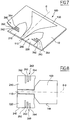
- auxiliary ground plane 300 is connected to each of the two blocks 210, 220 forming the coplanar ground plane 200 of the monopole 100 via a plurality of electrically conductive pins 310 passing through the substrate 10.
- the power supply of the antenna is made between the lower auxiliary ground plane 300 and the power supply line 110.
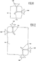
- FIG. figure 16 a first embodiment comprising two coplanar antennas of the type described above, orthogonal to each other, while it has been shown on FIG. figure 17 annexed, another variant comprising four coplanar antennas of the type previously described orthogonal two by two, distributed in the form of a pair at two diagonally opposite corners of the substrate.
- the diet of antennas according to the variants represented on the Figures 16 and 17 is provided between a ground plane provided on the lower surface 14 of the substrate 10 and the feed line 110.
Landscapes
- Engineering & Computer Science (AREA)
- Computer Networks & Wireless Communication (AREA)
- Details Of Aerials (AREA)
Claims (16)
- Antenne insbesondere für die Verbreitung von Breitbanddiensten umfassend:- einen Träger (10) aus dielektrischem Material, der die folgenden in Drucktechnik ausgeführten Elemente trägt:- einen mit einer Versorgungsleitung in der Ausführung eines koplanaren Leiters (110) verbundenen Monopol (100), und- eine koplanare Grundplatte (200) bestehend aus zwei jeweils an beiden Seiten der Versorgungsleitung (110) angeordneten Blöcken (210, 220), wobei sie von dieser getrennt sind,wobei sich der Monopol (100) mit zunehmendem Abstand zur Grundplatte (200) konisch erweitert und diese einen zum Monopol (100) gerichteten Rand (244-249; 250-254; 250-258) aufweist, der nicht vollständig gerade ist, dadurch gekennzeichnet, dass der Rand der Grundplatte in Richtung des Monopols konkav oder konvex ist, und dadurch gekennzeichnet, dass wenigstens der Monopol (100) Leitungen mit Schlitzen (174, 178; 274, 278) und/oder Löchern und/oder Ringen zum Einführen von Sekundärresonanzmoden umfasst.
- Antenne nach Anspruch 1, dadurch gekennzeichnet, dass die Grundplatte (200) Leitungen mit Schlitzen (274, 278) und/oder Löchern (282) und/oder Ringen (284) zum Einführen von Sekundärresonanzmoden umfasst.
- Antenne nach Anspruch 1 oder 2, dadurch gekennzeichnet, dass der Rand der Grundplatte (200) eine Spitze in Richtung des Monopols (100) bildet.
- Antenne nach einem der Ansprüche 1 bis 3, dadurch gekennzeichnet, dass der Rand der Grundplatte (200) eine durchgehende Krümmung aufweist.
- Antenne nach einem der Ansprüche 1 bis 4, dadurch gekennzeichnet, dass der Rand der Grundplatte (200) durch eine Abfolge von geraden Abschnitten abgegrenzt ist.
- Antenne nach einem der Ansprüche 1 bis 5, dadurch gekennzeichnet, dass die Grundplatte (200) eine im Wesentlichen polygonale Form aufweist.
- Antenne nach einem der Ansprüche 1 bis 6, dadurch gekennzeichnet, dass der Monopol (100) eine Symmetrie in Bezug auf eine durch die Versorgungsleitung (110) laufende Ebene aufweist.
- Antenne nach einem der Ansprüche 1 bis 6, dadurch gekennzeichnet, dass der Monopol (100) asymmetrisch ist.
- Antenne nach einem der Ansprüche 1 bis 8, dadurch gekennzeichnet, dass die Versorgungsleitung (110) aus einem geraden Band gebildet wird.
- Antenne nach einem der Ansprüche 1 bis 9, dadurch gekennzeichnet, dass der Träger aus dielektrischem Material (10) eine Hilfsgrundplatte (300) an seiner Seite gegenüber dem Monopol (100) aufweist, wobei die Hilfsgrundplatte (300) mit der koplanaren Grundplatte (200) des Monopols durch den Träger durchquerende leitende Stifte (310) verbunden ist.
- Antenne nach einem der Ansprüche 1 bis 10, dadurch gekennzeichnet, dass der zur Grundplatte (200) gerichtete Rand des Monopols (100) eine durchgehende Krümmung aufweist.
- Antenne nach einem der Ansprüche 1 bis 10, dadurch gekennzeichnet, dass der zur Grundplatte (200) gerichtete Rand des Monopols (100) durch eine Reihe von aufeinander folgenden geraden Abschnitten definiert ist.
- Antenne nach einem der Ansprüche 1 bis 12, dadurch gekennzeichnet, dass der Monopol (100) und/oder die Grundplatte (200) Nuten (262, 263, 264; 162, 163, 164) umfassen, die an den Flanken von diesen münden.
- Antenne nach einem der Ansprüche 1 bis 13, dadurch gekennzeichnet, dass ein Kurzschluss (170) den Monopol (100) und die Grundplatte (200) verbindet.
- Antenne nach einem der Ansprüche 1 bis 14, dadurch gekennzeichnet, dass sie zwei koplanare orthogonale Monopole umfasst.
- Antenne nach einem der Ansprüche 1 bis 15, dadurch gekennzeichnet, dass sie vier koplanare Monopole in der Form von zwei an den gegenüberliegenden Winkeln des Trägers (10) angeordneten Paaren orthogonaler Monopole umfasst.
Priority Applications (1)
| Application Number | Priority Date | Filing Date | Title |
|---|---|---|---|
| EP04290421.9A EP1564842B1 (de) | 2004-02-17 | 2004-02-17 | Ultrabreitbandige Antenne |
Applications Claiming Priority (1)
| Application Number | Priority Date | Filing Date | Title |
|---|---|---|---|
| EP04290421.9A EP1564842B1 (de) | 2004-02-17 | 2004-02-17 | Ultrabreitbandige Antenne |
Publications (2)
| Publication Number | Publication Date |
|---|---|
| EP1564842A1 EP1564842A1 (de) | 2005-08-17 |
| EP1564842B1 true EP1564842B1 (de) | 2017-12-20 |
Family
ID=34684789
Family Applications (1)
| Application Number | Title | Priority Date | Filing Date |
|---|---|---|---|
| EP04290421.9A Expired - Lifetime EP1564842B1 (de) | 2004-02-17 | 2004-02-17 | Ultrabreitbandige Antenne |
Country Status (1)
| Country | Link |
|---|---|
| EP (1) | EP1564842B1 (de) |
Families Citing this family (18)
| Publication number | Priority date | Publication date | Assignee | Title |
|---|---|---|---|---|
| EP1684382A1 (de) * | 2005-01-19 | 2006-07-26 | Samsung Electronics Co., Ltd. | Kleine extrem breitbandige Antenne mit gerichtetem Strahlungsdiagramm |
| EP1786064A1 (de) | 2005-11-09 | 2007-05-16 | Sony Deutschland GmbH | Flache Antennenanordnung für Ultrabreitbandanwendungen |
| US7498987B2 (en) * | 2005-12-20 | 2009-03-03 | Motorola, Inc. | Electrically small low profile switched multiband antenna |
| JP4527671B2 (ja) * | 2006-01-30 | 2010-08-18 | 日星電気株式会社 | 広帯域アンテナエレメント |
| GB2439110B (en) * | 2006-06-13 | 2009-08-19 | Thales Holdings Uk Plc | An ultra wideband antenna |
| CN101569056B (zh) * | 2006-12-22 | 2012-08-15 | 艾利森电话股份有限公司 | 集成在印刷电路板中的天线 |
| GB2448747B (en) * | 2007-04-27 | 2012-02-22 | Antenova Ltd | Antenna device with crenellated groundplane |
| TWI347710B (en) * | 2007-09-20 | 2011-08-21 | Delta Networks Inc | Multi-mode resonator broadband antenna |
| TW200931716A (en) * | 2008-01-14 | 2009-07-16 | Asustek Comp Inc | Antenna module |
| GB0901475D0 (en) * | 2009-01-29 | 2009-03-11 | Univ Birmingham | Multifunctional antenna |
| CN101610310B (zh) * | 2009-07-07 | 2013-05-15 | 惠州Tcl移动通信有限公司 | 一种移动通讯终端 |
| JP2011061758A (ja) * | 2009-08-10 | 2011-03-24 | Fujitsu Component Ltd | アンテナ装置 |
| GB201122324D0 (en) * | 2011-12-23 | 2012-02-01 | Univ Edinburgh | Antenna element & antenna device comprising such elements |
| GB2517907B (en) * | 2013-08-09 | 2018-04-11 | Drayson Tech Europe Ltd | RF Energy Harvester |
| US9997836B2 (en) | 2014-04-02 | 2018-06-12 | Lg Electronics Inc. | Reradiation antenna and wireless charger |
| CN104022343B (zh) * | 2014-06-23 | 2016-05-18 | 北京邮电大学 | 多频段天线 |
| CN104993225B (zh) * | 2015-06-23 | 2017-10-20 | 浙江工商大学 | 一种应用于wlan的小型化g型单极子天线 |
| CN111211415B (zh) * | 2020-03-09 | 2022-02-01 | 西南交通大学 | 一种小型化超宽带微带天线及电路板组件 |
Family Cites Families (4)
| Publication number | Priority date | Publication date | Assignee | Title |
|---|---|---|---|---|
| DE19729664C2 (de) * | 1997-07-11 | 2001-02-22 | Inst Mobil Und Satellitenfunkt | Planare Breitbandantenne |
| CN1545749A (zh) * | 2001-09-13 | 2004-11-10 | �����ɷ� | 用于微型和多频带天线的多级和空间填充接地板 |
| US6603429B1 (en) * | 2002-02-21 | 2003-08-05 | Centurion Wireless Tech., Inc. | Multi-band planar antenna |
| US6937193B2 (en) * | 2002-06-04 | 2005-08-30 | Skycross, Inc. | Wideband printed monopole antenna |
-
2004
- 2004-02-17 EP EP04290421.9A patent/EP1564842B1/de not_active Expired - Lifetime
Non-Patent Citations (1)
| Title |
|---|
| None * |
Also Published As
| Publication number | Publication date |
|---|---|
| EP1564842A1 (de) | 2005-08-17 |
Similar Documents
| Publication | Publication Date | Title |
|---|---|---|
| EP1564842A1 (de) | Ultrabreitbandige Antenne | |
| EP2808946B1 (de) | Vorrichtung zum Verhindern einer Ausbreitung von elektromagnetischen Wellen und ihr Herstellungsprozess | |
| CA2024992C (fr) | Antenne plane | |
| EP0825673A1 (de) | Ebene gedruckte Antenne mit kurzgeschlossenen übereinanderliegenden Elementen | |
| FR2960710A1 (fr) | Element rayonnant a double polarisation d'antenne multibande | |
| FR3070224A1 (fr) | Antenne plaquee presentant deux modes de rayonnement differents a deux frequences de travail distinctes, dispositif utilisant une telle antenne | |
| FR2826185A1 (fr) | Antenne fil-plaque multifrequences | |
| FR2709833A1 (fr) | Instrument d'écoute large bande et bande basse pour applications spatiales. | |
| EP3235058B1 (de) | Drahtplattenantenne mit einem kapazitiven dach mit einem schlitz zwischen der speisungssonde und dem kurzschlussdraht | |
| EP1589608A1 (de) | RF kompakte Antenne | |
| CA2460820C (fr) | Antenne a large bande ou multi-bandes | |
| EP3022802B1 (de) | Stöpselantenne sowie antennenstruktur und antennenanordnung damit | |
| FR3052617A1 (fr) | Antenne wifi compacte a reflecteur en metamateriau | |
| EP1540768B1 (de) | Helixförmige breitbandantenne | |
| EP1805848B1 (de) | Mehrbandige bedruckte helixförmige schlitzantenne | |
| FR2814285A1 (fr) | Antenne helicoidale a pas variable, et procede correspondant | |
| FR2709604A1 (fr) | Antenne pour appareil radio portatif. | |
| CA2808511C (fr) | Antenne plane pour terminal fonctionnant en double polarisation circulaire, terminal aeroporte et systeme de telecommunication par satellite comportant au moins une telle antenne | |
| EP2409361A1 (de) | Zweirippen-antenne | |
| EP0991135B1 (de) | Selektive Antenne mit Frequenzumschaltung | |
| WO2016075387A1 (fr) | Dispositif antenne compacte reconfigurable | |
| FR2917242A1 (fr) | Perfectionnement aux antennes large bande. | |
| FR2980647A1 (fr) | Antenne ultra-large bande | |
| EP1025620B1 (de) | Abstrahlendes koaxialkabel | |
| FR2911998A1 (fr) | Antenne large bande |
Legal Events
| Date | Code | Title | Description |
|---|---|---|---|
| PUAI | Public reference made under article 153(3) epc to a published international application that has entered the european phase |
Free format text: ORIGINAL CODE: 0009012 |
|
| AK | Designated contracting states |
Kind code of ref document: A1 Designated state(s): AT BE BG CH CY CZ DE DK EE ES FI FR GB GR HU IE IT LI LU MC NL PT RO SE SI SK TR |
|
| AX | Request for extension of the european patent |
Extension state: AL LT LV MK |
|
| 17P | Request for examination filed |
Effective date: 20060217 |
|
| AKX | Designation fees paid |
Designated state(s): AT BE BG CH CY CZ DE DK EE ES FI FR GB GR HU IE IT LI LU MC NL PT RO SE SI SK TR |
|
| 17Q | First examination report despatched |
Effective date: 20070507 |
|
| RAP1 | Party data changed (applicant data changed or rights of an application transferred) |
Owner name: ORANGE |
|
| GRAP | Despatch of communication of intention to grant a patent |
Free format text: ORIGINAL CODE: EPIDOSNIGR1 |
|
| INTG | Intention to grant announced |
Effective date: 20170609 |
|
| RIN1 | Information on inventor provided before grant (corrected) |
Inventor name: BRACHAT, PATRICE Inventor name: RATAJCZAK, PHILIPPE Inventor name: DESVILLES, JEAN-LOUIS |
|
| GRAS | Grant fee paid |
Free format text: ORIGINAL CODE: EPIDOSNIGR3 |
|
| GRAJ | Information related to disapproval of communication of intention to grant by the applicant or resumption of examination proceedings by the epo deleted |
Free format text: ORIGINAL CODE: EPIDOSDIGR1 |
|
| GRAL | Information related to payment of fee for publishing/printing deleted |
Free format text: ORIGINAL CODE: EPIDOSDIGR3 |
|
| GRAR | Information related to intention to grant a patent recorded |
Free format text: ORIGINAL CODE: EPIDOSNIGR71 |
|
| GRAA | (expected) grant |
Free format text: ORIGINAL CODE: 0009210 |
|
| INTC | Intention to grant announced (deleted) | ||
| AK | Designated contracting states |
Kind code of ref document: B1 Designated state(s): AT BE BG CH CY CZ DE DK EE ES FI FR GB GR HU IE IT LI LU MC NL PT RO SE SI SK TR |
|
| INTG | Intention to grant announced |
Effective date: 20171113 |
|
| REG | Reference to a national code |
Ref country code: GB Ref legal event code: FG4D Free format text: NOT ENGLISH |
|
| REG | Reference to a national code |
Ref country code: CH Ref legal event code: EP |
|
| REG | Reference to a national code |
Ref country code: IE Ref legal event code: FG4D Free format text: LANGUAGE OF EP DOCUMENT: FRENCH |
|
| REG | Reference to a national code |
Ref country code: AT Ref legal event code: REF Ref document number: 957169 Country of ref document: AT Kind code of ref document: T Effective date: 20180115 |
|
| REG | Reference to a national code |
Ref country code: DE Ref legal event code: R096 Ref document number: 602004052190 Country of ref document: DE |
|
| REG | Reference to a national code |
Ref country code: FR Ref legal event code: PLFP Year of fee payment: 15 |
|
| REG | Reference to a national code |
Ref country code: NL Ref legal event code: MP Effective date: 20171220 |
|
| PG25 | Lapsed in a contracting state [announced via postgrant information from national office to epo] |
Ref country code: SE Free format text: LAPSE BECAUSE OF FAILURE TO SUBMIT A TRANSLATION OF THE DESCRIPTION OR TO PAY THE FEE WITHIN THE PRESCRIBED TIME-LIMIT Effective date: 20171220 Ref country code: FI Free format text: LAPSE BECAUSE OF FAILURE TO SUBMIT A TRANSLATION OF THE DESCRIPTION OR TO PAY THE FEE WITHIN THE PRESCRIBED TIME-LIMIT Effective date: 20171220 |
|
| REG | Reference to a national code |
Ref country code: AT Ref legal event code: MK05 Ref document number: 957169 Country of ref document: AT Kind code of ref document: T Effective date: 20171220 |
|
| PG25 | Lapsed in a contracting state [announced via postgrant information from national office to epo] |
Ref country code: GR Free format text: LAPSE BECAUSE OF FAILURE TO SUBMIT A TRANSLATION OF THE DESCRIPTION OR TO PAY THE FEE WITHIN THE PRESCRIBED TIME-LIMIT Effective date: 20180321 Ref country code: BG Free format text: LAPSE BECAUSE OF FAILURE TO SUBMIT A TRANSLATION OF THE DESCRIPTION OR TO PAY THE FEE WITHIN THE PRESCRIBED TIME-LIMIT Effective date: 20180320 |
|
| PG25 | Lapsed in a contracting state [announced via postgrant information from national office to epo] |
Ref country code: NL Free format text: LAPSE BECAUSE OF FAILURE TO SUBMIT A TRANSLATION OF THE DESCRIPTION OR TO PAY THE FEE WITHIN THE PRESCRIBED TIME-LIMIT Effective date: 20171220 |
|
| PG25 | Lapsed in a contracting state [announced via postgrant information from national office to epo] |
Ref country code: CY Free format text: LAPSE BECAUSE OF FAILURE TO SUBMIT A TRANSLATION OF THE DESCRIPTION OR TO PAY THE FEE WITHIN THE PRESCRIBED TIME-LIMIT Effective date: 20171220 Ref country code: EE Free format text: LAPSE BECAUSE OF FAILURE TO SUBMIT A TRANSLATION OF THE DESCRIPTION OR TO PAY THE FEE WITHIN THE PRESCRIBED TIME-LIMIT Effective date: 20171220 Ref country code: CZ Free format text: LAPSE BECAUSE OF FAILURE TO SUBMIT A TRANSLATION OF THE DESCRIPTION OR TO PAY THE FEE WITHIN THE PRESCRIBED TIME-LIMIT Effective date: 20171220 Ref country code: SK Free format text: LAPSE BECAUSE OF FAILURE TO SUBMIT A TRANSLATION OF THE DESCRIPTION OR TO PAY THE FEE WITHIN THE PRESCRIBED TIME-LIMIT Effective date: 20171220 Ref country code: ES Free format text: LAPSE BECAUSE OF FAILURE TO SUBMIT A TRANSLATION OF THE DESCRIPTION OR TO PAY THE FEE WITHIN THE PRESCRIBED TIME-LIMIT Effective date: 20171220 |
|
| PG25 | Lapsed in a contracting state [announced via postgrant information from national office to epo] |
Ref country code: AT Free format text: LAPSE BECAUSE OF FAILURE TO SUBMIT A TRANSLATION OF THE DESCRIPTION OR TO PAY THE FEE WITHIN THE PRESCRIBED TIME-LIMIT Effective date: 20171220 Ref country code: IT Free format text: LAPSE BECAUSE OF FAILURE TO SUBMIT A TRANSLATION OF THE DESCRIPTION OR TO PAY THE FEE WITHIN THE PRESCRIBED TIME-LIMIT Effective date: 20171220 Ref country code: RO Free format text: LAPSE BECAUSE OF FAILURE TO SUBMIT A TRANSLATION OF THE DESCRIPTION OR TO PAY THE FEE WITHIN THE PRESCRIBED TIME-LIMIT Effective date: 20171220 |
|
| REG | Reference to a national code |
Ref country code: CH Ref legal event code: PL |
|
| REG | Reference to a national code |
Ref country code: DE Ref legal event code: R097 Ref document number: 602004052190 Country of ref document: DE |
|
| PG25 | Lapsed in a contracting state [announced via postgrant information from national office to epo] |
Ref country code: MC Free format text: LAPSE BECAUSE OF FAILURE TO SUBMIT A TRANSLATION OF THE DESCRIPTION OR TO PAY THE FEE WITHIN THE PRESCRIBED TIME-LIMIT Effective date: 20171220 |
|
| PLBE | No opposition filed within time limit |
Free format text: ORIGINAL CODE: 0009261 |
|
| STAA | Information on the status of an ep patent application or granted ep patent |
Free format text: STATUS: NO OPPOSITION FILED WITHIN TIME LIMIT |
|
| 26N | No opposition filed |
Effective date: 20180921 |
|
| REG | Reference to a national code |
Ref country code: IE Ref legal event code: MM4A |
|
| REG | Reference to a national code |
Ref country code: BE Ref legal event code: MM Effective date: 20180228 |
|
| PG25 | Lapsed in a contracting state [announced via postgrant information from national office to epo] |
Ref country code: LU Free format text: LAPSE BECAUSE OF NON-PAYMENT OF DUE FEES Effective date: 20180217 Ref country code: LI Free format text: LAPSE BECAUSE OF NON-PAYMENT OF DUE FEES Effective date: 20180228 Ref country code: DK Free format text: LAPSE BECAUSE OF FAILURE TO SUBMIT A TRANSLATION OF THE DESCRIPTION OR TO PAY THE FEE WITHIN THE PRESCRIBED TIME-LIMIT Effective date: 20171220 Ref country code: CH Free format text: LAPSE BECAUSE OF NON-PAYMENT OF DUE FEES Effective date: 20180228 |
|
| PG25 | Lapsed in a contracting state [announced via postgrant information from national office to epo] |
Ref country code: IE Free format text: LAPSE BECAUSE OF NON-PAYMENT OF DUE FEES Effective date: 20180217 |
|
| PG25 | Lapsed in a contracting state [announced via postgrant information from national office to epo] |
Ref country code: SI Free format text: LAPSE BECAUSE OF FAILURE TO SUBMIT A TRANSLATION OF THE DESCRIPTION OR TO PAY THE FEE WITHIN THE PRESCRIBED TIME-LIMIT Effective date: 20171220 Ref country code: BE Free format text: LAPSE BECAUSE OF NON-PAYMENT OF DUE FEES Effective date: 20180228 |
|
| PG25 | Lapsed in a contracting state [announced via postgrant information from national office to epo] |
Ref country code: TR Free format text: LAPSE BECAUSE OF FAILURE TO SUBMIT A TRANSLATION OF THE DESCRIPTION OR TO PAY THE FEE WITHIN THE PRESCRIBED TIME-LIMIT Effective date: 20171220 |
|
| PG25 | Lapsed in a contracting state [announced via postgrant information from national office to epo] |
Ref country code: HU Free format text: LAPSE BECAUSE OF FAILURE TO SUBMIT A TRANSLATION OF THE DESCRIPTION OR TO PAY THE FEE WITHIN THE PRESCRIBED TIME-LIMIT; INVALID AB INITIO Effective date: 20040217 Ref country code: PT Free format text: LAPSE BECAUSE OF FAILURE TO SUBMIT A TRANSLATION OF THE DESCRIPTION OR TO PAY THE FEE WITHIN THE PRESCRIBED TIME-LIMIT Effective date: 20171220 |
|
| PGFP | Annual fee paid to national office [announced via postgrant information from national office to epo] |
Ref country code: DE Payment date: 20210120 Year of fee payment: 18 Ref country code: GB Payment date: 20210120 Year of fee payment: 18 |
|
| REG | Reference to a national code |
Ref country code: DE Ref legal event code: R119 Ref document number: 602004052190 Country of ref document: DE |
|
| GBPC | Gb: european patent ceased through non-payment of renewal fee |
Effective date: 20220217 |
|
| PG25 | Lapsed in a contracting state [announced via postgrant information from national office to epo] |
Ref country code: GB Free format text: LAPSE BECAUSE OF NON-PAYMENT OF DUE FEES Effective date: 20220217 Ref country code: DE Free format text: LAPSE BECAUSE OF NON-PAYMENT OF DUE FEES Effective date: 20220901 |
|
| PGFP | Annual fee paid to national office [announced via postgrant information from national office to epo] |
Ref country code: FR Payment date: 20230119 Year of fee payment: 20 |