EP1564465A1 - Magnetdoppelventil - Google Patents
Magnetdoppelventil Download PDFInfo
- Publication number
- EP1564465A1 EP1564465A1 EP20040026476 EP04026476A EP1564465A1 EP 1564465 A1 EP1564465 A1 EP 1564465A1 EP 20040026476 EP20040026476 EP 20040026476 EP 04026476 A EP04026476 A EP 04026476A EP 1564465 A1 EP1564465 A1 EP 1564465A1
- Authority
- EP
- European Patent Office
- Prior art keywords
- convex
- concave
- shaft
- magnetic double
- valve according
- Prior art date
- Legal status (The legal status is an assumption and is not a legal conclusion. Google has not performed a legal analysis and makes no representation as to the accuracy of the status listed.)
- Granted
Links
- 230000009977 dual effect Effects 0.000 title 1
- 230000005540 biological transmission Effects 0.000 claims abstract description 33
- 238000004519 manufacturing process Methods 0.000 description 3
- 230000000694 effects Effects 0.000 description 1
- 230000005764 inhibitory process Effects 0.000 description 1
- 238000009434 installation Methods 0.000 description 1
- 230000003993 interaction Effects 0.000 description 1
- 239000006228 supernatant Substances 0.000 description 1
Images


Classifications
-
- F—MECHANICAL ENGINEERING; LIGHTING; HEATING; WEAPONS; BLASTING
- F16—ENGINEERING ELEMENTS AND UNITS; GENERAL MEASURES FOR PRODUCING AND MAINTAINING EFFECTIVE FUNCTIONING OF MACHINES OR INSTALLATIONS; THERMAL INSULATION IN GENERAL
- F16K—VALVES; TAPS; COCKS; ACTUATING-FLOATS; DEVICES FOR VENTING OR AERATING
- F16K31/00—Actuating devices; Operating means; Releasing devices
- F16K31/02—Actuating devices; Operating means; Releasing devices electric; magnetic
- F16K31/06—Actuating devices; Operating means; Releasing devices electric; magnetic using a magnet, e.g. diaphragm valves, cutting off by means of a liquid
- F16K31/10—Actuating devices; Operating means; Releasing devices electric; magnetic using a magnet, e.g. diaphragm valves, cutting off by means of a liquid with additional mechanism between armature and closure member
-
- Y—GENERAL TAGGING OF NEW TECHNOLOGICAL DEVELOPMENTS; GENERAL TAGGING OF CROSS-SECTIONAL TECHNOLOGIES SPANNING OVER SEVERAL SECTIONS OF THE IPC; TECHNICAL SUBJECTS COVERED BY FORMER USPC CROSS-REFERENCE ART COLLECTIONS [XRACs] AND DIGESTS
- Y10—TECHNICAL SUBJECTS COVERED BY FORMER USPC
- Y10T—TECHNICAL SUBJECTS COVERED BY FORMER US CLASSIFICATION
- Y10T137/00—Fluid handling
- Y10T137/8593—Systems
- Y10T137/877—With flow control means for branched passages
- Y10T137/87708—With common valve operator
- Y10T137/87772—With electrical actuation
Definitions
- the invention relates to a magnetic double valve specified in the preamble of claim 1 Art.
- Such, known in practice magnetic double valves are, for example, as a valve core assembly designed to be in a flow path containing body in too the flow paths leading receiving bores is used, for example to control certain valve functions by means of the two valve members. Since the common solenoid to actuate both valve members in the closing direction against valve seats has, and because of unavoidable manufacturing tolerances the actuation strokes up to the closing positions and the opposing forces of the valve members to be different can, the sliding fit of the power transmission member in the sliding guide so chosen as narrow as possible, so that the sliding guide a tilting of the power transmission member largely excludes.
- the closing positions and the closing forces are not reliably defined because of inevitable Manufacturing or assembly tolerances in the valve seats can be a closing element not reliably reach its tight closing position when the power transmission member due to its tight sliding fit, only the previously attached valve member is correct applied.
- the power transmission member for adjusting the valve members in the opening direction to form as a movable balance beam, which tilt under the force of a common magnet depending thereon can, which valve member is difficult to open.
- a stationary abutment surface for the balance beam also brings the other valve member on the balance beam in the open position.
- the invention is based on the object, a magnetic double valve of the aforementioned To create kind with improved functional safety and simple structure, in particular a magnetic double valve, the short-stroke magnet for adjusting having the two valve members in their closed positions.
- the radial safety clearance between the shaft of the power transmission member and the sliding guide and the magnetic force transmitting Tilting joint surprisingly long service life with trouble-free operation of the magnetic double valve. Even if the valve members due to tolerances in the direction of movement
- the anchor should have different closing positions, that of the magnet generated magnetic force distributed to both valve members so that each valve member its Closing position securely assumes and also sits with the required clamping force and is tight.
- the transmission link may be due to the security game in the Slightly tilt sliding guide. In an inclined position of the power transmission point moves for the magnetic force in the tilting joint optionally from a first central position even to the side at which the former valve member is present, but only by a smaller amount than the width of the surfaces in the tilt joint. Thereby the valve member, which attaches later, is reliably brought into its closed position, and is also in tilting joint no significant lateral force from the magnetic force generated, which jam the power transmission member in the sliding guide could.
- the tilting joint on the anchor or on an axially guided anchor tappet and on the shaft directly or indirectly contacting each other first and second Investment surfaces in a special geometric pairing on.
- This pairing can be: flat / convex or concave / concave or convex / concave or convex / convex, where the respective convex or concave surface at least one arc of curvature in the Level has, in which the two valve members are adjacent. This results in the power transmission necessary for placement of both valve members mobility and the desirable effect that the power transfer point between the surfaces barely emigrated from the middle.
- the concave or convex arc curvature may be a circular arc curvature, either part of a cylindrical surface with the plane of the valve members vertical Cylinder axis, or part of a spherical surface with the center of the ball in the axis the anchor, the anchor tappet and / or the shaft.
- the training of these areas is manufacturing technology easy.
- the arc curvatures may be the same or the convex Arc curvature to be stronger than the concave arc curvature. It results from this no planar power transmission, but a power transmission with point or Line contact, which is advantageous for mobility in the tilting joint.
- planar first and second contact surfaces can also be provided in the tilting joint be, with one contact surface is significantly smaller than the other and, for example is formed on a central extension. This results in a mobility similar to a ball joint without too strong lateral emigration of the Power transmission point.
- the first and second contact surfaces expedient: flat / flat or even / concave or even / convex or concave / concave or concave / convex or convex / convex.
- a contact surface a centric, recessed ball seat with a diameter smaller than the ball diameter. Any movements then find between the other contact surface and the ball joint.
- the first and second contact surfaces can be sized differently.
- the sliding guide is expediently designed as at least one plain bearing bush, which sits in a receiving bore of the fixed core part of the magnet.
- the Power transmission member is connected to the e.g. cylindrical shaft in the plain bearing book guided, with the safety clearance between the shaft and the plain bearing bush is provided.
- This safety clearance can be about 2% of the inside diameter of the sliding guide be. This results in a relatively loose sliding fit, which, however, for a magnetic double valve, in which both valve members of a magnet on the tilting joint be adjusted in the closed positions, is appropriate.
- valve core assembly a structurally simple concept of a valve core assembly is achieved, when each valve member is placed in an insert sleeve, above a threaded sleeve is provided, in which an actuating tappet for the valve member out becomes.
- the force transmission member is the Einschraubhülse with a distance opposite, by a projection of the actuating plunger on the screw is dimensioned so large that when reaching the closed positions of the valve members between the power transmission member and the screw-in sleeves a gap remains and the power transmission member not to stop on a stationary surface comes.
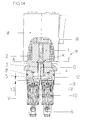
- Fig. 1 shows a magnetic double valve D, for example, a double valve insert, for installation in receiving bores of a hydraulic valve block connected to flow channels 15, in which two in a plane (in Fig. 1 in the drawing plane) adjacent to each other Valve members V have to fulfill certain valve functions.
- the two valve members V are by a common magnet M, here a Kurzhubmagneten, operated to move against spring force from opening positions to their shown closing positions be adjusted to seats 14 and held with certain closing forces.
- the magnet includes an armature B and a movable in a fixed core part 1
- An armature plunger 2 which acts on a force transmission member G with the magnetic force to to actuate the two valve members V.
- the power transmission member G is T-shaped and with a shaft 4 in a sliding guide 3 in the fixed core part 1 slidably guided.
- the shaft 4 is integrally united with a transverse part 5.
- valve members V are seated valve members, each sealed in an insert sleeve 10 slidably guided and seats 14 are opposite.
- the insert sleeves 10 are installed in bores of the block 15 sealed with the valve members V, wherein the Valve members V arranged in flow channels 7 springs 6 in lifting direction be acted upon by the seats 14.
- Above the insert sleeves 10 are screwed 9 introduced, which fix the insert sleeves 10 in the mounting positions.
- actuation tappets 11 are sealed for the valve members V. guided.
- Each actuating plunger 11 protrudes beyond the top of the screw 9 and cooperates with the transverse part 5 of the power transmission member G together.
- the supernatant the actuating tappet 11 is chosen so that even with energized magnet and on the seats 14 held valve members V (closed positions) the underside of Cross members 5 of the power transmission member G is a distance 13 to the tops of the Screw-in sleeves 9 complies, and does not come to a stop.
- the magnet M can over an intermediate ring 12 with a seal 8 also be inserted into the block 15.
- the sliding guide 3 is at least one plain bearing bush for the shaft 4.
- the armature B could act directly on the power transmission member G.
- the double solenoid valve D in Fig. 1A also contains as the two valve members V.
- Poppet valve members each of which alternately with an upper and a lower seat works together (two 3/2-way valve functions).
- the upper closing positions are set by the springs 6, the lower by the single magnet M.
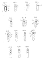
- a tilt joint K above the sliding guide 3 is provided, which in detail how may be shown in Figs. 2 - 18 shown.
- Fig. 2 is a detail sectional view of Fig. 1 or Fig. 1A for emphasizing the interaction between the armature plunger 2 and the shaft 4 of the power transmission member G in the tilting joint K.
- the shaft 4 has in this embodiment, one in the drawing plane, i.e. which defined by the axes of the two valve members V in Fig. 1, Fig. 1A Plane, convexly curved contact surface.
- the contact surface is part, for example a cylindrical surface with a cylinder axis Y perpendicular to the plane of the two valve members V, or is part of a spherical surface (spherical center Y).
- the anchor tappet 2 has a plane counter surface F, which is perpendicular to the ram axis.
- the shaft 4 is with a radial safety clearance X recorded in the sliding guide 3.
- the security game For example, X is about 2% of the inner diameter of the slide guide 3. At an inner diameter of about 5 mm, the entire
- the counter surface F contacted for transmitting the magnetic force the contact surface A, so that the tilting joint K is formed.
- the contact surface A is e.g. larger than the counterface F.
- the two surfaces could be the same size.
- the contact surface A is convexly curved (cylindrical surface or spherical surface), and is also the counter surface F curved in the same direction, i. concave (cylindrical or spherical), optionally with a larger radius of curvature than the contact surface A.
- the abutment surface A is concavely curved (cylindrical or spherical), while the Counterface F is convexly curved (cylindrical or spherical).
- both the abutment surface A and the counter surface F are convexly curved (spherical or cylindrical), i. in opposite directions convex.
- the power transmission member G can anyway only in one biased so that it would be sufficient, only one at a time Central region of the contact surface A and / or the counter surface F convex or concave to shape.
- FIGs. 6 and 7 illustrate what happens if the left in Fig. 1, Fig. 1A valve member V makes a higher resistance or assumes its closed position earlier than that other valve member V.
- the shaft 4 tilts with its axis Z in relation to the through the Anchor tappet 2 fixed axis of movement Z 'of the armature in a clockwise direction, namely in the context of the safety clearance X.
- This causes either (FIG. 6) the point of contact for transmitting the magnetic force in the tilting joint K from the central position of Fig. 2 displaces slightly to the left and therefore transmit the magnetic force slightly off-center or, (Fig.
- the tilting joint K is formed by the flat counter surface F on the anchor tappet 2 and by one of them much smaller, e.g. plane, contact surface A ', the is formed centrally on a centrally shaped extension D of the shaft 4.
- the extension D could also be formed on the armature plunger 2.
- a joint ball G between the abutment and Counter surfaces A, F placed the surfaces in the following geometric pairings may be: Eben / even in Fig. 9; plane / convex in Fig. 10; flat / concave in Fig. 11; even / just with one or two centric ball seat recess (s) S in Fig. 12 and Fig. 18; convex / convex in Fig. 13; concave / convex in Fig. 14; even / convex or even / concave with a centric ball seat recess S in Fig. 15 or Fig. 17; and concave / concave in FIG. 16.
- the diameter of the joint ball G corresponds approximately to the diameter of the anchor tappet 2 and / or the shaft 4.
- the joint ball G could also be slightly smaller and in the Shaft 4 or sunk in the anchor tappet 2 and / or caulked and / or pressed firmly be positioned, and so form a convex surface, similar to in Fig. 2, in the tilting joint K.
Landscapes
- Engineering & Computer Science (AREA)
- General Engineering & Computer Science (AREA)
- Mechanical Engineering (AREA)
- Magnetically Actuated Valves (AREA)
Abstract
Description
- Fig. 1
- einen Teillängsschnitt eines Magnetdoppelventils (zwei 2/2-Wegeventile) mit erregtem Magneten,
- Fig. 1A
- einen Teillängsschnitt eines anderen Magnetdoppelventils (zwei 3/2-Wegeventile), mit erregtem Magneten, und
- Fig. 2 bis 18
- verschiedene Varianten eines Kippgelenks für das Magnetdoppelventil, wobei Fig. 2, 6 und 7 das in den Fig. 1 und 1A gezeigte Kippgelenk verdeutlichen.
Claims (13)
- Magnetdoppelventil (D), mit zwei nebeneinander liegenden Ventilgliedern (V), die gegen Federkraft (6) durch einen gemeinsamen Magneten (M) über ein mit einem Schaft (4) in einer Schiebeführung (3) geführtes, T-förmiges Kraftübertragungsglied (G) in Schließrichtung betätigbar sind, dadurch gekennzeichnet, dass zwischen der Schiebeführung (3) und dem Schaft (4) ein radiales Sicherheitsspiel (X) vorgesehen ist, und dass an der den Ventilgliedern (V) abgewandten Seite der Schiebeführung (3) zwischen dem Schaft (4) des Kraftübertragungsgliedes (G) und dem Anker (B) oder einem beweglich geführten Ankerstößel (2) des Magneten (M) ein Kippgelenk (K) vorgesehen ist.
- Magnetdoppelventil nach Anspruch 1, dadurch gekennzeichnet, dass das Kippgelenk (K) am Anker (B) oder an dem Ankerstößel (2) und am Schaft (4) direkt oder indirekt einander kontaktierende erste und zweite Anlageflächen (A, F) in der geometrischen Paarung: Eben/konvex oder konkav/konkav oder konvex/konkav oder konvex/konvex, umfasst, wobei die jeweils konvexe oder konkave Anlagefläche (A, F) zumindest eine Bogenkrümmung in der Ebene aufweist, in der die beiden Ventilglieder (V) nebeneinander liegen.
- Magnetdoppelventil nach Anspruch 2, dadurch gekennzeichnet, dass die konkave oder konvexe Bogenkrümmung eine Kreisbogenkrümmung ist, deren Krümmungszentrum (Y) in der Achse des Ankers (B) bzw. Ankerstößels (2) und/oder des Schafts (4) liegt, vorzugsweise ein Teil einer Zylinderfläche mit zur Ebene der Ventilglieder (V) senkrecht der Zylinderachse (Y).
- Magnetdoppelventil nach Anspruch 2, dadurch gekennzeichnet, dass die jeweils konvexe oder konkave Anlagefläche (A, F) Teil einer Kugelfläche mit dem Zentrum (Y) in der Achse des Ankers (B) bzw. Ankerstößels (2) und/oder des Schafts (4) ist.
- Magnetdoppelventil nach Anspruch 2, dadurch gekennzeichnet, dass in der geometrischen Paarung konkav/konvex die Bogenkrümmungen gleich sind oder die konvexe Bogenkrümmung stärker als die konkave Bogenkrümmung ist.
- Magnetdoppelventil nach Anspruch 1, dadurch gekennzeichnet, dass das Kippgelenk (K) aus einer ebenen Anlagefläche (F) am Schaft (4) oder am Anker (B) bzw. am Ankerstößel (2) und einer ebenfalls ebenen Anlagefläche (A') mit gegenüber der Gegenfläche (F) kleineren Durchmesser an einem zentrischen Fortsatz (D) der jeweils anderen Komponente von dem Anker (B) bzw. dem Ankerstößel (2) oder dem Schaft (4) gebildet ist.
- Magnetdoppelventil nach Anspruch 2, dadurch gekennzeichnet, dass im Kippgelenk (K) zwischen der Anlagefläche und der Gegenfläche (A, F) eine Gelenkkugel (G) angeordnet ist.
- Magnetdoppelventil nach Anspruch 7, dadurch gekennzeichnet, dass die die Gelenkkugel (G) zwischen sich einschließenden Anlageflächen (A, F) in der geometrischen Paarung: Eben/eben oder eben/konkav oder eben/konvex oder konkav/konkav oder konkav/konvex oder konvex/konvex, ausgebildet sind.
- Magnetdoppelventil nach Anspruch 8, dadurch gekennzeichnet, dass zumindest eine eben ausgebildete Anlagefläche (A, F) eine zentrische Kugelsitzvertiefung (S) mit einem Durchmesser kleiner als dem Kugeldurchmesser aufweist.
- Magnetdoppelventil nach wenigstens einem der vorhergehenden Ansprüche, dadurch gekennzeichnet, dass die Anlageflächen (A', A, F) unterschiedlich groß sind.
- Magnetdoppelventil nach Anspruch 1, dadurch gekennzeichnet, dass die Schiebeführung (3) wenigstens eine Gleitlagerbuchse ist, die in einer Aufnahmebohrung eines festen Kernteils (1) des Magneten (M) sitzt, dass das Kraftübertragungsglied (G) mit einem zylindrischen Schaft (4) die Gleitlagerbuchse durchsetzt, und dass das Sicherheitsspiel (X) zwischen dem Schaft (4) und der Gleitlagerbuchse gebildet ist.
- Magnetdoppelventil nach Anspruch 1, dadurch gekennzeichnet, dass das Sicherheitsspiel (X) ca. 2 % des Innendurchmessers der Schiebeführung (3) beträgt.
- Magnetdoppelventil nach Anspruch 1, dadurch gekennzeichnet, dass jedes Ventilglied (V) in einer Einsatzhülse (10) angeordnet ist, dass oberhalb der Einsatzhülse (10) eine Einschraubhülse (9) vorgesehen ist, in der ein Betätigungsstößel (11) geführt ist, dass das Kraftübertragungsglied (G) der Einschraubhülse (9) mit einem Abstand (13) gegenüberliegt, und dass der Betätigungsstößel (11) so weit über die Einschraubhülse (9) vorsteht, dass bei erregtem Magneten (M) und erreichter Schließposition des Ventilgliedes (V) zwischen dem Kraftübertragungsglied (G) und der Einschraubhülse ein Zwischenraum verbleibt.
Applications Claiming Priority (2)
| Application Number | Priority Date | Filing Date | Title |
|---|---|---|---|
| DE200420002432 DE202004002432U1 (de) | 2004-02-17 | 2004-02-17 | Magnetdoppelventil |
| DE202004002432U | 2004-02-17 |
Publications (2)
| Publication Number | Publication Date |
|---|---|
| EP1564465A1 true EP1564465A1 (de) | 2005-08-17 |
| EP1564465B1 EP1564465B1 (de) | 2007-01-17 |
Family
ID=34684171
Family Applications (1)
| Application Number | Title | Priority Date | Filing Date |
|---|---|---|---|
| EP20040026476 Expired - Lifetime EP1564465B1 (de) | 2004-02-17 | 2004-11-08 | Magnetdoppelventil |
Country Status (4)
| Country | Link |
|---|---|
| US (1) | US7219697B2 (de) |
| EP (1) | EP1564465B1 (de) |
| DE (2) | DE202004002432U1 (de) |
| ES (1) | ES2280882T3 (de) |
Cited By (3)
| Publication number | Priority date | Publication date | Assignee | Title |
|---|---|---|---|---|
| US8235011B2 (en) | 2007-08-08 | 2012-08-07 | Daimler Ag | Actuating device |
| EP2535600A1 (de) | 2011-06-16 | 2012-12-19 | HAWE Hydraulik SE | Wegeventil |
| EP2636927A1 (de) * | 2012-03-07 | 2013-09-11 | Honda Motor Co., Ltd. | Ventilvorrichtung und Fehlerdetektor einer hydraulischen Schaltung |
Families Citing this family (5)
| Publication number | Priority date | Publication date | Assignee | Title |
|---|---|---|---|---|
| DE102012218593A1 (de) * | 2012-10-12 | 2014-04-17 | Continental Automotive Gmbh | Ventil für eine Pumpe |
| US9583249B2 (en) | 2014-10-31 | 2017-02-28 | Husco Automotive Holdings Llc | Methods and systems for push pin actuator |
| DE102017200058A1 (de) * | 2017-01-04 | 2018-07-05 | Continental Teves Ag & Co. Ohg | Elektromagnetventil |
| DE102018215900A1 (de) * | 2018-09-19 | 2020-03-19 | Continental Teves Ag & Co. Ohg | Elektromagnetventil, insbesondere für schlupfgeregelte Kraftfahrzeugbremsanlagen |
| EP4450826A1 (de) * | 2023-04-21 | 2024-10-23 | Hamilton Sundstrand Corporation | Einstufige servoventilanordnung |
Citations (4)
| Publication number | Priority date | Publication date | Assignee | Title |
|---|---|---|---|---|
| US2708561A (en) | 1952-02-18 | 1955-05-17 | Ap Controls Corp | Four-way valve |
| DE1085736B (de) | 1956-07-23 | 1960-07-21 | Roger Charles Dubois | Magnetventil fuer Fluessigkeiten aller Druckbereiche |
| EP0527393A1 (de) | 1991-08-12 | 1993-02-17 | HEILMEIER & WEINLEIN Fabrik für Oel-Hydraulik GmbH & Co. KG | Magnetventil-Vorrichtung |
| EP1036965A1 (de) | 1999-03-18 | 2000-09-20 | HEILMEIER & WEINLEIN Fabrik für Oel-Hydraulik GmbH & Co. KG | Ventilverband |
Family Cites Families (2)
| Publication number | Priority date | Publication date | Assignee | Title |
|---|---|---|---|---|
| US1202895A (en) * | 1916-02-29 | 1916-10-31 | George M Rogers | Machine-oiler. |
| US4494572A (en) * | 1982-09-30 | 1985-01-22 | Humphrey Products Company | Four-way poppet valve assembly |
-
2004
- 2004-02-17 DE DE200420002432 patent/DE202004002432U1/de not_active Expired - Lifetime
- 2004-11-08 EP EP20040026476 patent/EP1564465B1/de not_active Expired - Lifetime
- 2004-11-08 ES ES04026476T patent/ES2280882T3/es not_active Expired - Lifetime
- 2004-11-08 DE DE200450002669 patent/DE502004002669D1/de not_active Expired - Lifetime
-
2005
- 2005-02-10 US US11/055,337 patent/US7219697B2/en not_active Expired - Fee Related
Patent Citations (4)
| Publication number | Priority date | Publication date | Assignee | Title |
|---|---|---|---|---|
| US2708561A (en) | 1952-02-18 | 1955-05-17 | Ap Controls Corp | Four-way valve |
| DE1085736B (de) | 1956-07-23 | 1960-07-21 | Roger Charles Dubois | Magnetventil fuer Fluessigkeiten aller Druckbereiche |
| EP0527393A1 (de) | 1991-08-12 | 1993-02-17 | HEILMEIER & WEINLEIN Fabrik für Oel-Hydraulik GmbH & Co. KG | Magnetventil-Vorrichtung |
| EP1036965A1 (de) | 1999-03-18 | 2000-09-20 | HEILMEIER & WEINLEIN Fabrik für Oel-Hydraulik GmbH & Co. KG | Ventilverband |
Cited By (3)
| Publication number | Priority date | Publication date | Assignee | Title |
|---|---|---|---|---|
| US8235011B2 (en) | 2007-08-08 | 2012-08-07 | Daimler Ag | Actuating device |
| EP2535600A1 (de) | 2011-06-16 | 2012-12-19 | HAWE Hydraulik SE | Wegeventil |
| EP2636927A1 (de) * | 2012-03-07 | 2013-09-11 | Honda Motor Co., Ltd. | Ventilvorrichtung und Fehlerdetektor einer hydraulischen Schaltung |
Also Published As
| Publication number | Publication date |
|---|---|
| US20050178453A1 (en) | 2005-08-18 |
| ES2280882T3 (es) | 2007-09-16 |
| US7219697B2 (en) | 2007-05-22 |
| EP1564465B1 (de) | 2007-01-17 |
| DE502004002669D1 (de) | 2007-03-08 |
| DE202004002432U1 (de) | 2005-07-07 |
Similar Documents
| Publication | Publication Date | Title |
|---|---|---|
| DE2315425C2 (de) | Elektromagnetisch betätigtes Wegeventil | |
| EP1301837B1 (de) | Proportional-druckregelventil | |
| DE19655090C2 (de) | Elektromagnetisch betätigtes Wegeventil | |
| EP2906815B1 (de) | Ventil für eine pumpe | |
| DE19700980A1 (de) | Elektromagnetventil | |
| EP2685145A2 (de) | Ventil | |
| DE10203886A1 (de) | Vorsteuerventil | |
| EP1564465B1 (de) | Magnetdoppelventil | |
| EP1591856B1 (de) | Druckregelventil | |
| DE19716856B4 (de) | Baueinheit für ein Hydraulikventil | |
| DE3521040A1 (de) | Einspritzventil | |
| DE102004015661B4 (de) | Elektropneumatisches Ventil, insbesondere Vorsteuerventil für ein pneumatisches Wegeventil | |
| EP0123938B1 (de) | Elektromagnetisch betätigbares Ventil | |
| DE69401263T2 (de) | Proportionales elektromagnetisch gesteuertes druckluftventil | |
| DE4301308C2 (de) | Hydraulik-Ventil | |
| DE19607019A1 (de) | Vorrichtung zur elektromagnetischen Betätigung eines Gaswechselventiles für Verbrennungsmotoren | |
| DE19834786C2 (de) | Elektromagnetisches Wegesitzventil | |
| DE10255524B4 (de) | Elektromagnetisches 3/2-Wegesitzventil mit A-Kompensation | |
| DE10306003B4 (de) | Antriebseinrichtung für Ventile | |
| DE69422284T2 (de) | Hydraulischer Stossdämpfer | |
| DE102022205870A1 (de) | Elektromagnetventil für eine Kraftfahrzeugbremsanlage mit einem Mittel zur Restluftspalteinstellung und ein Verfahren zur Montage eines Elektromagnetventils | |
| DE19618272A1 (de) | Magnetventil | |
| DE4111064A1 (de) | Wegeventil mit zwei beabstandeten ventilkoerpern | |
| DE3620242C2 (de) | ||
| EP2778437B1 (de) | Hydraulisches Ventil |
Legal Events
| Date | Code | Title | Description |
|---|---|---|---|
| PUAI | Public reference made under article 153(3) epc to a published international application that has entered the european phase |
Free format text: ORIGINAL CODE: 0009012 |
|
| AK | Designated contracting states |
Kind code of ref document: A1 Designated state(s): AT BE BG CH CY CZ DE DK EE ES FI FR GB GR HU IE IS IT LI LU MC NL PL PT RO SE SI SK TR |
|
| AX | Request for extension of the european patent |
Extension state: AL HR LT LV MK YU |
|
| 17P | Request for examination filed |
Effective date: 20050914 |
|
| AKX | Designation fees paid |
Designated state(s): CH DE ES FR IT LI |
|
| GRAP | Despatch of communication of intention to grant a patent |
Free format text: ORIGINAL CODE: EPIDOSNIGR1 |
|
| GRAS | Grant fee paid |
Free format text: ORIGINAL CODE: EPIDOSNIGR3 |
|
| GRAA | (expected) grant |
Free format text: ORIGINAL CODE: 0009210 |
|
| AK | Designated contracting states |
Kind code of ref document: B1 Designated state(s): CH DE ES FR IT LI |
|
| REG | Reference to a national code |
Ref country code: CH Ref legal event code: NV Representative=s name: PATENTANWALTSBUERO JEAN HUNZIKER Ref country code: CH Ref legal event code: EP |
|
| REF | Corresponds to: |
Ref document number: 502004002669 Country of ref document: DE Date of ref document: 20070308 Kind code of ref document: P |
|
| ET | Fr: translation filed | ||
| REG | Reference to a national code |
Ref country code: ES Ref legal event code: FG2A Ref document number: 2280882 Country of ref document: ES Kind code of ref document: T3 |
|
| PLBE | No opposition filed within time limit |
Free format text: ORIGINAL CODE: 0009261 |
|
| STAA | Information on the status of an ep patent application or granted ep patent |
Free format text: STATUS: NO OPPOSITION FILED WITHIN TIME LIMIT |
|
| 26N | No opposition filed |
Effective date: 20071018 |
|
| PGFP | Annual fee paid to national office [announced via postgrant information from national office to epo] |
Ref country code: FR Payment date: 20131118 Year of fee payment: 10 Ref country code: ES Payment date: 20131119 Year of fee payment: 10 |
|
| REG | Reference to a national code |
Ref country code: FR Ref legal event code: ST Effective date: 20150731 |
|
| PG25 | Lapsed in a contracting state [announced via postgrant information from national office to epo] |
Ref country code: FR Free format text: LAPSE BECAUSE OF NON-PAYMENT OF DUE FEES Effective date: 20141201 |
|
| REG | Reference to a national code |
Ref country code: ES Ref legal event code: FD2A Effective date: 20151229 |
|
| PG25 | Lapsed in a contracting state [announced via postgrant information from national office to epo] |
Ref country code: ES Free format text: LAPSE BECAUSE OF NON-PAYMENT OF DUE FEES Effective date: 20141109 |
|
| PGFP | Annual fee paid to national office [announced via postgrant information from national office to epo] |
Ref country code: IT Payment date: 20151130 Year of fee payment: 12 |
|
| REG | Reference to a national code |
Ref country code: DE Ref legal event code: R082 Ref document number: 502004002669 Country of ref document: DE Representative=s name: GROSSE, SCHUMACHER, KNAUER, VON HIRSCHHAUSEN, DE |
|
| PG25 | Lapsed in a contracting state [announced via postgrant information from national office to epo] |
Ref country code: IT Free format text: LAPSE BECAUSE OF NON-PAYMENT OF DUE FEES Effective date: 20161108 |
|
| REG | Reference to a national code |
Ref country code: DE Ref legal event code: R082 Ref document number: 502004002669 Country of ref document: DE Representative=s name: GROSSE, SCHUMACHER, KNAUER, VON HIRSCHHAUSEN, DE Ref country code: DE Ref legal event code: R081 Ref document number: 502004002669 Country of ref document: DE Owner name: HAWE HYDRAULIK SE, DE Free format text: FORMER OWNER: HAWE HYDRAULIK GMBH & CO. KG, 81673 MUENCHEN, DE |
|
| REG | Reference to a national code |
Ref country code: CH Ref legal event code: PFA Owner name: HAWE HYDRAULIK SE, DE Free format text: FORMER OWNER: HAWE HYDRAULIK GMBH AND CO. KG, DE |
|
| REG | Reference to a national code |
Ref country code: DE Ref legal event code: R082 Ref document number: 502004002669 Country of ref document: DE Representative=s name: GROSSE, SCHUMACHER, KNAUER, VON HIRSCHHAUSEN, DE Ref country code: DE Ref legal event code: R081 Ref document number: 502004002669 Country of ref document: DE Owner name: HAWE HYDRAULIK SE, DE Free format text: FORMER OWNER: HAWE HYDRAULIK SE, 81673 MUENCHEN, DE |
|
| REG | Reference to a national code |
Ref country code: CH Ref legal event code: PFUS Owner name: HAWE HYDRAULIK SE, DE Free format text: FORMER OWNER: HAWE HYDRAULIK SE, DE |
|
| PGFP | Annual fee paid to national office [announced via postgrant information from national office to epo] |
Ref country code: DE Payment date: 20211119 Year of fee payment: 18 |
|
| PGFP | Annual fee paid to national office [announced via postgrant information from national office to epo] |
Ref country code: CH Payment date: 20211123 Year of fee payment: 18 |
|
| REG | Reference to a national code |
Ref country code: DE Ref legal event code: R119 Ref document number: 502004002669 Country of ref document: DE |
|
| P01 | Opt-out of the competence of the unified patent court (upc) registered |
Effective date: 20230523 |
|
| REG | Reference to a national code |
Ref country code: CH Ref legal event code: PL |
|
| PG25 | Lapsed in a contracting state [announced via postgrant information from national office to epo] |
Ref country code: LI Free format text: LAPSE BECAUSE OF NON-PAYMENT OF DUE FEES Effective date: 20221130 Ref country code: CH Free format text: LAPSE BECAUSE OF NON-PAYMENT OF DUE FEES Effective date: 20221130 |
|
| PG25 | Lapsed in a contracting state [announced via postgrant information from national office to epo] |
Ref country code: DE Free format text: LAPSE BECAUSE OF NON-PAYMENT OF DUE FEES Effective date: 20230601 |