EP1564452A1 - Dichtleiste - Google Patents
Dichtleiste Download PDFInfo
- Publication number
- EP1564452A1 EP1564452A1 EP20050001642 EP05001642A EP1564452A1 EP 1564452 A1 EP1564452 A1 EP 1564452A1 EP 20050001642 EP20050001642 EP 20050001642 EP 05001642 A EP05001642 A EP 05001642A EP 1564452 A1 EP1564452 A1 EP 1564452A1
- Authority
- EP
- European Patent Office
- Prior art keywords
- sealing strip
- cover
- layer
- tear
- substance
- Prior art date
- Legal status (The legal status is an assumption and is not a legal conclusion. Google has not performed a legal analysis and makes no representation as to the accuracy of the status listed.)
- Granted
Links
Images


Classifications
-
- F—MECHANICAL ENGINEERING; LIGHTING; HEATING; WEAPONS; BLASTING
- F16—ENGINEERING ELEMENTS AND UNITS; GENERAL MEASURES FOR PRODUCING AND MAINTAINING EFFECTIVE FUNCTIONING OF MACHINES OR INSTALLATIONS; THERMAL INSULATION IN GENERAL
- F16J—PISTONS; CYLINDERS; SEALINGS
- F16J15/00—Sealings
- F16J15/02—Sealings between relatively-stationary surfaces
- F16J15/06—Sealings between relatively-stationary surfaces with solid packing compressed between sealing surfaces
- F16J15/061—Sealings between relatively-stationary surfaces with solid packing compressed between sealing surfaces with positioning means
-
- B—PERFORMING OPERATIONS; TRANSPORTING
- B60—VEHICLES IN GENERAL
- B60J—WINDOWS, WINDSCREENS, NON-FIXED ROOFS, DOORS, OR SIMILAR DEVICES FOR VEHICLES; REMOVABLE EXTERNAL PROTECTIVE COVERINGS SPECIALLY ADAPTED FOR VEHICLES
- B60J10/00—Sealing arrangements
- B60J10/15—Sealing arrangements characterised by the material
- B60J10/16—Sealing arrangements characterised by the material consisting of two or more plastic materials having different physical or chemical properties
-
- B—PERFORMING OPERATIONS; TRANSPORTING
- B60—VEHICLES IN GENERAL
- B60J—WINDOWS, WINDSCREENS, NON-FIXED ROOFS, DOORS, OR SIMILAR DEVICES FOR VEHICLES; REMOVABLE EXTERNAL PROTECTIVE COVERINGS SPECIALLY ADAPTED FOR VEHICLES
- B60J10/00—Sealing arrangements
- B60J10/30—Sealing arrangements characterised by the fastening means
- B60J10/34—Sealing arrangements characterised by the fastening means using adhesives
-
- B—PERFORMING OPERATIONS; TRANSPORTING
- B60—VEHICLES IN GENERAL
- B60J—WINDOWS, WINDSCREENS, NON-FIXED ROOFS, DOORS, OR SIMILAR DEVICES FOR VEHICLES; REMOVABLE EXTERNAL PROTECTIVE COVERINGS SPECIALLY ADAPTED FOR VEHICLES
- B60J10/00—Sealing arrangements
- B60J10/45—Assembling sealing arrangements with vehicle parts
-
- F—MECHANICAL ENGINEERING; LIGHTING; HEATING; WEAPONS; BLASTING
- F16—ENGINEERING ELEMENTS AND UNITS; GENERAL MEASURES FOR PRODUCING AND MAINTAINING EFFECTIVE FUNCTIONING OF MACHINES OR INSTALLATIONS; THERMAL INSULATION IN GENERAL
- F16J—PISTONS; CYLINDERS; SEALINGS
- F16J15/00—Sealings
- F16J15/02—Sealings between relatively-stationary surfaces
- F16J15/06—Sealings between relatively-stationary surfaces with solid packing compressed between sealing surfaces
- F16J15/10—Sealings between relatively-stationary surfaces with solid packing compressed between sealing surfaces with non-metallic packing
- F16J15/104—Sealings between relatively-stationary surfaces with solid packing compressed between sealing surfaces with non-metallic packing characterised by structure
-
- Y—GENERAL TAGGING OF NEW TECHNOLOGICAL DEVELOPMENTS; GENERAL TAGGING OF CROSS-SECTIONAL TECHNOLOGIES SPANNING OVER SEVERAL SECTIONS OF THE IPC; TECHNICAL SUBJECTS COVERED BY FORMER USPC CROSS-REFERENCE ART COLLECTIONS [XRACs] AND DIGESTS
- Y10—TECHNICAL SUBJECTS COVERED BY FORMER USPC
- Y10T—TECHNICAL SUBJECTS COVERED BY FORMER US CLASSIFICATION
- Y10T428/00—Stock material or miscellaneous articles
- Y10T428/14—Layer or component removable to expose adhesive
- Y10T428/1452—Polymer derived only from ethylenically unsaturated monomer
-
- Y—GENERAL TAGGING OF NEW TECHNOLOGICAL DEVELOPMENTS; GENERAL TAGGING OF CROSS-SECTIONAL TECHNOLOGIES SPANNING OVER SEVERAL SECTIONS OF THE IPC; TECHNICAL SUBJECTS COVERED BY FORMER USPC CROSS-REFERENCE ART COLLECTIONS [XRACs] AND DIGESTS
- Y10—TECHNICAL SUBJECTS COVERED BY FORMER USPC
- Y10T—TECHNICAL SUBJECTS COVERED BY FORMER US CLASSIFICATION
- Y10T428/00—Stock material or miscellaneous articles
- Y10T428/14—Layer or component removable to expose adhesive
- Y10T428/1462—Polymer derived from material having at least one acrylic or alkacrylic group or the nitrile or amide derivative thereof [e.g., acrylamide, acrylate ester, etc.]
-
- Y—GENERAL TAGGING OF NEW TECHNOLOGICAL DEVELOPMENTS; GENERAL TAGGING OF CROSS-SECTIONAL TECHNOLOGIES SPANNING OVER SEVERAL SECTIONS OF THE IPC; TECHNICAL SUBJECTS COVERED BY FORMER USPC CROSS-REFERENCE ART COLLECTIONS [XRACs] AND DIGESTS
- Y10—TECHNICAL SUBJECTS COVERED BY FORMER USPC
- Y10T—TECHNICAL SUBJECTS COVERED BY FORMER US CLASSIFICATION
- Y10T428/00—Stock material or miscellaneous articles
- Y10T428/14—Layer or component removable to expose adhesive
- Y10T428/1471—Protective layer
-
- Y—GENERAL TAGGING OF NEW TECHNOLOGICAL DEVELOPMENTS; GENERAL TAGGING OF CROSS-SECTIONAL TECHNOLOGIES SPANNING OVER SEVERAL SECTIONS OF THE IPC; TECHNICAL SUBJECTS COVERED BY FORMER USPC CROSS-REFERENCE ART COLLECTIONS [XRACs] AND DIGESTS
- Y10—TECHNICAL SUBJECTS COVERED BY FORMER USPC
- Y10T—TECHNICAL SUBJECTS COVERED BY FORMER US CLASSIFICATION
- Y10T428/00—Stock material or miscellaneous articles
- Y10T428/14—Layer or component removable to expose adhesive
- Y10T428/1476—Release layer
-
- Y—GENERAL TAGGING OF NEW TECHNOLOGICAL DEVELOPMENTS; GENERAL TAGGING OF CROSS-SECTIONAL TECHNOLOGIES SPANNING OVER SEVERAL SECTIONS OF THE IPC; TECHNICAL SUBJECTS COVERED BY FORMER USPC CROSS-REFERENCE ART COLLECTIONS [XRACs] AND DIGESTS
- Y10—TECHNICAL SUBJECTS COVERED BY FORMER USPC
- Y10T—TECHNICAL SUBJECTS COVERED BY FORMER US CLASSIFICATION
- Y10T428/00—Stock material or miscellaneous articles
- Y10T428/14—Layer or component removable to expose adhesive
- Y10T428/1486—Ornamental, decorative, pattern, or indicia
-
- Y—GENERAL TAGGING OF NEW TECHNOLOGICAL DEVELOPMENTS; GENERAL TAGGING OF CROSS-SECTIONAL TECHNOLOGIES SPANNING OVER SEVERAL SECTIONS OF THE IPC; TECHNICAL SUBJECTS COVERED BY FORMER USPC CROSS-REFERENCE ART COLLECTIONS [XRACs] AND DIGESTS
- Y10—TECHNICAL SUBJECTS COVERED BY FORMER USPC
- Y10T—TECHNICAL SUBJECTS COVERED BY FORMER US CLASSIFICATION
- Y10T428/00—Stock material or miscellaneous articles
- Y10T428/14—Layer or component removable to expose adhesive
- Y10T428/149—Sectional layer removable
-
- Y—GENERAL TAGGING OF NEW TECHNOLOGICAL DEVELOPMENTS; GENERAL TAGGING OF CROSS-SECTIONAL TECHNOLOGIES SPANNING OVER SEVERAL SECTIONS OF THE IPC; TECHNICAL SUBJECTS COVERED BY FORMER USPC CROSS-REFERENCE ART COLLECTIONS [XRACs] AND DIGESTS
- Y10—TECHNICAL SUBJECTS COVERED BY FORMER USPC
- Y10T—TECHNICAL SUBJECTS COVERED BY FORMER US CLASSIFICATION
- Y10T428/00—Stock material or miscellaneous articles
- Y10T428/22—Nonparticulate element embedded or inlaid in substrate and visible
-
- Y—GENERAL TAGGING OF NEW TECHNOLOGICAL DEVELOPMENTS; GENERAL TAGGING OF CROSS-SECTIONAL TECHNOLOGIES SPANNING OVER SEVERAL SECTIONS OF THE IPC; TECHNICAL SUBJECTS COVERED BY FORMER USPC CROSS-REFERENCE ART COLLECTIONS [XRACs] AND DIGESTS
- Y10—TECHNICAL SUBJECTS COVERED BY FORMER USPC
- Y10T—TECHNICAL SUBJECTS COVERED BY FORMER US CLASSIFICATION
- Y10T428/00—Stock material or miscellaneous articles
- Y10T428/24—Structurally defined web or sheet [e.g., overall dimension, etc.]
- Y10T428/24132—Structurally defined web or sheet [e.g., overall dimension, etc.] including grain, strips, or filamentary elements in different layers or components parallel
-
- Y—GENERAL TAGGING OF NEW TECHNOLOGICAL DEVELOPMENTS; GENERAL TAGGING OF CROSS-SECTIONAL TECHNOLOGIES SPANNING OVER SEVERAL SECTIONS OF THE IPC; TECHNICAL SUBJECTS COVERED BY FORMER USPC CROSS-REFERENCE ART COLLECTIONS [XRACs] AND DIGESTS
- Y10—TECHNICAL SUBJECTS COVERED BY FORMER USPC
- Y10T—TECHNICAL SUBJECTS COVERED BY FORMER US CLASSIFICATION
- Y10T428/00—Stock material or miscellaneous articles
- Y10T428/249921—Web or sheet containing structurally defined element or component
- Y10T428/249953—Composite having voids in a component [e.g., porous, cellular, etc.]
- Y10T428/249982—With component specified as adhesive or bonding agent
-
- Y—GENERAL TAGGING OF NEW TECHNOLOGICAL DEVELOPMENTS; GENERAL TAGGING OF CROSS-SECTIONAL TECHNOLOGIES SPANNING OVER SEVERAL SECTIONS OF THE IPC; TECHNICAL SUBJECTS COVERED BY FORMER USPC CROSS-REFERENCE ART COLLECTIONS [XRACs] AND DIGESTS
- Y10—TECHNICAL SUBJECTS COVERED BY FORMER USPC
- Y10T—TECHNICAL SUBJECTS COVERED BY FORMER US CLASSIFICATION
- Y10T428/00—Stock material or miscellaneous articles
- Y10T428/249921—Web or sheet containing structurally defined element or component
- Y10T428/249953—Composite having voids in a component [e.g., porous, cellular, etc.]
- Y10T428/249987—With nonvoid component of specified composition
- Y10T428/249991—Synthetic resin or natural rubbers
Definitions
- the invention relates to a sealing strip according to the preamble of claim 1.
- connection with the one part can, with appropriate design of the Sealing strip form-fit by elastic latching done - is common provided a bond.
- the sealing strip regularly from a, the actual sealing effect mediating layer, which is coated on one side with an adhesive layer, wherein the adhesive layer Your turn is covered with a cover.
- the auxiliary which is used for the manual Detachment of the cover is determined formed by only a tear thread is that used in the substance of the cover or anchored in this is.
- the thread is dimensioned to the extent and material selected that he suitable for transmitting the force sufficient to detach the cover sheet is. Accordingly, the connection between the thread and the cover sheet set up.
- This tool which preferably made Plastic, a significantly lower material usage and as a result positive connection with the cover a greater reliability.
- Along the sealing strip can have one or more tear-off threads be provided.
- the tear thread is according to the features of claim 2 at both Ends provided with flat retaining elements. After the tear thread the Substance of the cover penetrates, form these flat retaining elements at the same time anchoring elements on which ultimately the form-fitting Composite can be based on the cover.
- These flat retaining elements can, for example, in the form of rectangular plates, but also Crossbars are present, which are perpendicular to the longitudinal extent of the tear thread run.
- the process of establishing a connection between the ripcords and the cover sheet can be mechanized according to the features of claim 3 be carried out by pressing or shooting. Also is controllable in this way, that the tear thread only the substance of the Cover film, but not other layers of the sealing strips penetrates.
- the visible surface of the sealing strip forming layer can according to the Characteristics of claim 4, for example made of rubber or other Elastomer consist, which also used in a foam-like consistency whereas the adhesive layer is made of acrylic foam.
- the invention can in principle be applied to any sealing strips for mounting with a covered by a cover adhesive layer are prepared, regardless of the adhesive system or the material composition of the adhesive layer.
- the sealing strip can according to the features of claims 5 and 6 in provided a linear, but also an annular structure for the user and in any case with one or more ripcords stocked. It offers compared to the above-mentioned prior art considerable advantages in terms of their production costs, but in particular also in terms of their practical handling properties during the assembly.
- a cold glue such as e.g. Acrylic foam
- the cover 4 is either material or in a conventional manner due to their surface coating in coordination with the adhesive system
- the layer 3 chosen to the effect that this no permanent connection or bonding with the layer 3 received and in any case of this is solvable.
- tear-off tabs 6 are provided along the Sealing strip 1 .
- These tear-off tabs can be made of polyethylene and must be individual are glued to the outside of the cover 4. This bond must be such that a detection of the tear-off 6 a Removing the cover 4 for the purpose of exposing the layer 3 is possible and it these tear-off tabs regularly have such a planar extension, which allows a comfortable manual detection.
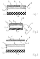
- the sealing strip 1 ' is in the initial state in the same manner in a wound Form and is - starting from this state - according to specification unwound discrete length elements, each of which according to the invention now is provided with at least one tear thread 7.
- the example from Polyethylene ripcord 7 extends through the substance of the cover 4 through and is at its two, out of this outstanding Ends with hooks, extensions or other preferred flat retaining elements 8, 8 'provided, which in any case a simple extraction of the tear thread 7 form-fittingly oppose from the substance of the cover.
- These retaining elements 8, 8 ' also have such a size and / or Texture, which is a manual capture and then a peel allow the cover 4 of the layer 3.
- a known stapling device 9 which equipped with a setting needle 10.
- the tear thread 7 points to the Set a position shown schematically in Fig. 1, wherein along a precut Length element of the sealing strip 1 'at least one, preferably a plurality of spaced apart tear threads 7 can be set.
- sealing strip 1 ' according to the invention is designed similar to that of the sealing strip 1 of FIG. 4. That is, it is by Manual detection of one of the two holding elements 8, 8 'of the tear thread 7 the Covering film 4 removed from the layer 3, so that the latter is exposed and thus provided for bonding with a mating surface of a motor vehicle structure becomes.
- the inventive, equipped with ripcords 7 sealing strip 1 ' is distinguished Compared to the above-described prior art by a extremely easy to manufacture, after the setting of the tear threads. 7 by shooting by means of the stapler 9, thus in a very short time feasible is. Added to this is the cost of materials for providing rip threads Significantly lower compared to the known tear-off.
- FIGS. 5 and 6 each show linear or annular structures according to the invention Sealing strips 11, 12 as they are provided by the user can.
Landscapes
- Engineering & Computer Science (AREA)
- Mechanical Engineering (AREA)
- General Engineering & Computer Science (AREA)
- Package Closures (AREA)
- Control And Other Processes For Unpacking Of Materials (AREA)
- Sealing Material Composition (AREA)
- Adhesives Or Adhesive Processes (AREA)
- Cartons (AREA)
- Laminated Bodies (AREA)
- Electroluminescent Light Sources (AREA)
- Adhesive Tapes (AREA)
Abstract
Description
Claims (6)
- Dichtleiste (1') zum Abdichten des Spaltes zwischen zwei relativ zueinander bewegbaren Teilen, insbesondere des Spaltes zwischen einer Kraftfahrzeugtür und der dieser zugeordneten Berandung einer Fahrzeugstruktur, mit einer zur Verklebung mit dem einen der beiden Teile bestimmten Fläche (5') sowie einer, in der Schließstellung für eine dichtende Anlage an dem anderen der beiden Teile bestimmten und ansonsten eine Sichtfläche darstellenden Fläche (5), bestehend zumindest aus einer, die Sichtfläche bildenden Schicht (2), deren der Fläche (5) abgekehrte Seite mit einer Schicht (3) aus einem Klebstoff überzogen ist, die ihrerseits mit einer, den Klebstoff in einem aktivierbaren Zustand haltenden, von diesem lösbaren, insbesondere nicht mit diesem verklebbarer Abdeckfolie (4) belegt ist und wobei an der Abdeckfolie (4) zumindest ein zu deren manueller Ablösung von der Schicht (3) bestimmtes Hilfsmittel befestigt ist, dadurch gekennzeichnet, dass das Hilfsmittel aus wenigstens einem, lediglich die Substanz der Abdeckfolie (4) durchdringenden sowie mit dieser in Verbindung stehenden Reißfaden (7) gebildet ist, dessen wenigstens eines freies Ende aus der Dichtleiste (1') herausragt.
- Dichtleiste (1') nach Anspruch 1, dadurch gekennzeichnet, dass beide Enden des Reißfadens (7) aus der Substanz der Abdeckfolie (4) herausragen und an ihren Enden bzw. auf ihren aus der Substanz herausragenden Abschnitten mit flächigen Halteelementen (8, 8') versehen sind.
- Dichtleiste (1') nach Anspruch 1 oder 2, dadurch gekennzeichnet, dass die Reißfäden (7) aus Kunststoff bestehende, in die Substanz der Abdeckfolie (4) eingepresste bzw. eingeschoßene Elemente sind.
- Dichtleiste (1') nach einem der vorangegangenen Ansprüche 1 bis 3 gekennzeichnet durch eine, die Sichtfläche bildende, aus Gummi oder einem sonstigen Elastomer bestehende Schicht (2) und eine, aus Acrylschaum bestehende Schicht (3) die mit einer, mit Acrylschaum nicht verklebbaren Abdeckfolie (4) belegt ist.
- Dichtleiste (1') nach einem der vorangegangenen Ansprüche 1 bis 4 gekennzeichnet durch eine lineare Gestalt.
- Dichtleiste nach einem der vorangegangenen Ansprüche 1 bis 4, gekennzeichnet durch eine, nach Art einer geschlossenen Kurve eingerichtete Gestalt.
Priority Applications (2)
| Application Number | Priority Date | Filing Date | Title |
|---|---|---|---|
| SI200530002T SI1564452T1 (sl) | 2004-02-13 | 2005-01-27 | Tesnilni trak |
| PL05001642T PL1564452T3 (pl) | 2004-02-13 | 2005-01-27 | Listwa uszczelniająca |
Applications Claiming Priority (2)
| Application Number | Priority Date | Filing Date | Title |
|---|---|---|---|
| DE202004002241U | 2004-02-13 | ||
| DE202004002241U DE202004002241U1 (de) | 2004-02-13 | 2004-02-13 | Dichtleiste |
Publications (2)
| Publication Number | Publication Date |
|---|---|
| EP1564452A1 true EP1564452A1 (de) | 2005-08-17 |
| EP1564452B1 EP1564452B1 (de) | 2006-06-14 |
Family
ID=34399877
Family Applications (1)
| Application Number | Title | Priority Date | Filing Date |
|---|---|---|---|
| EP20050001642 Expired - Lifetime EP1564452B1 (de) | 2004-02-13 | 2005-01-27 | Dichtleiste |
Country Status (9)
| Country | Link |
|---|---|
| US (1) | US7320819B2 (de) |
| EP (1) | EP1564452B1 (de) |
| AT (1) | ATE330152T1 (de) |
| CA (1) | CA2493694C (de) |
| DE (2) | DE202004002241U1 (de) |
| ES (1) | ES2262123T3 (de) |
| PL (1) | PL1564452T3 (de) |
| PT (1) | PT1564452E (de) |
| SI (1) | SI1564452T1 (de) |
Families Citing this family (7)
| Publication number | Priority date | Publication date | Assignee | Title |
|---|---|---|---|---|
| US20070024009A1 (en) * | 2005-07-29 | 2007-02-01 | Gerald Rosenquist | Gasket assembly |
| US20080120914A1 (en) * | 2006-09-22 | 2008-05-29 | Tt Technologies, Inc. | Pre-Hung Exterior Door Assembly and Sill Therefor |
| DE102008024609A1 (de) * | 2008-05-21 | 2009-12-10 | Artweger Gmbh & Co. | Dichtungsprofil |
| EP2138664B1 (de) * | 2008-06-23 | 2015-04-15 | ISO-Chemie GmbH | Vorkomprimiertes Dichtband |
| DE102010035775A1 (de) * | 2010-08-26 | 2012-03-01 | Ing. Haaga Werkzeugbau Gmbh & Co. Kg | Dichtungsprofil, Kehrmaschine umfassend ein Dichtungsprofil und Verfahren zum Anbringen eines Dichtungsprofils |
| CN107524804A (zh) * | 2017-09-15 | 2017-12-29 | 安徽省地坤汽车天窗科技有限公司 | 一种密封条 |
| DE102018207850B4 (de) * | 2018-05-18 | 2020-06-18 | Tesa Se | Stanzling zum dauerhaften Verschließen von Löchern |
Citations (2)
| Publication number | Priority date | Publication date | Assignee | Title |
|---|---|---|---|---|
| WO1999026801A1 (de) * | 1997-11-21 | 1999-06-03 | Meteor Gummiwerke K.H. Bädje Gmbh & Co. | Dichtsystem mit dichtungsprofil und klebeband |
| EP1502844A1 (de) * | 2003-07-30 | 2005-02-02 | Hutchinson | Vorrichtung zur dynamischen Anbringung einer Dichtung auf einem Substrat, beispielsweise einer Rahmenstruktur oder einem Karosserieelement eines Kraftfahrzeuges |
Family Cites Families (4)
| Publication number | Priority date | Publication date | Assignee | Title |
|---|---|---|---|---|
| US1243699A (en) * | 1912-01-08 | 1917-10-23 | Empire Paper Bottle Company | Sanitary closing and sealing device for containers. |
| US2770816A (en) * | 1955-09-06 | 1956-11-20 | Reisner Michael | Cushions and method of making the same |
| DE8129131U1 (de) * | 1981-10-05 | 1983-02-17 | Michael Müller KG, 8633 Rödental | Dichtungsstreifen zur abdichtung eines spaltes zwischen tuer und fussboden |
| US6235365B1 (en) * | 1998-12-18 | 2001-05-22 | W. R. Grace & Co.-Conn. | Waterproofing membrane having release sheet cutting system |
-
2004
- 2004-02-13 DE DE202004002241U patent/DE202004002241U1/de not_active Expired - Lifetime
- 2004-03-24 US US10/808,862 patent/US7320819B2/en not_active Expired - Fee Related
-
2005
- 2005-01-21 CA CA 2493694 patent/CA2493694C/en not_active Expired - Fee Related
- 2005-01-27 SI SI200530002T patent/SI1564452T1/sl unknown
- 2005-01-27 AT AT05001642T patent/ATE330152T1/de not_active IP Right Cessation
- 2005-01-27 EP EP20050001642 patent/EP1564452B1/de not_active Expired - Lifetime
- 2005-01-27 PT PT05001642T patent/PT1564452E/pt unknown
- 2005-01-27 DE DE200550000019 patent/DE502005000019D1/de not_active Expired - Lifetime
- 2005-01-27 PL PL05001642T patent/PL1564452T3/pl unknown
- 2005-01-27 ES ES05001642T patent/ES2262123T3/es not_active Expired - Lifetime
Patent Citations (2)
| Publication number | Priority date | Publication date | Assignee | Title |
|---|---|---|---|---|
| WO1999026801A1 (de) * | 1997-11-21 | 1999-06-03 | Meteor Gummiwerke K.H. Bädje Gmbh & Co. | Dichtsystem mit dichtungsprofil und klebeband |
| EP1502844A1 (de) * | 2003-07-30 | 2005-02-02 | Hutchinson | Vorrichtung zur dynamischen Anbringung einer Dichtung auf einem Substrat, beispielsweise einer Rahmenstruktur oder einem Karosserieelement eines Kraftfahrzeuges |
Also Published As
| Publication number | Publication date |
|---|---|
| SI1564452T1 (sl) | 2006-12-31 |
| DE202004002241U1 (de) | 2005-03-24 |
| CA2493694A1 (en) | 2005-08-13 |
| CA2493694C (en) | 2008-11-04 |
| US7320819B2 (en) | 2008-01-22 |
| ES2262123T3 (es) | 2006-11-16 |
| EP1564452B1 (de) | 2006-06-14 |
| US20050179218A1 (en) | 2005-08-18 |
| PL1564452T3 (pl) | 2006-10-31 |
| ATE330152T1 (de) | 2006-07-15 |
| PT1564452E (pt) | 2006-09-29 |
| DE502005000019D1 (de) | 2006-07-27 |
Similar Documents
| Publication | Publication Date | Title |
|---|---|---|
| EP2138665B1 (de) | Verfahren zum Abdichten einer Fuge mit einem vorkomprimierten Dichtband | |
| EP1959064B1 (de) | Rückstellfähiges Dichtband | |
| EP2666947B1 (de) | Dichtband | |
| WO2012048912A1 (de) | Klebeband sowie aus dem klebeband hergestellte schlauchummantelung | |
| EP3943261A1 (de) | Dichtband und verfahren zum herstellen eines dichtbandes | |
| EP3180405B1 (de) | Verfahren zur herstellung einer ummantelung für langgestrecktes gut | |
| DE4123647B4 (de) | Dichtband | |
| EP1564452B1 (de) | Dichtleiste | |
| EP0727376A2 (de) | Einrichtung zum Unterteilen einer sich bewegenden Papierbahn | |
| EP2101027A2 (de) | Dichtungsband und Verwendung eines Dichtungsbandes | |
| EP1381552A1 (de) | Klebemittel zur verbindung eines bahnanfanges einer materialrolle und verfahren | |
| DE102007061859A1 (de) | Verfahren zur Herstellung eines verstärkten Klebebandes | |
| DE102014000389B3 (de) | Passbuch und Verfahren zur Herstellung eines Sicherheitsdokuments | |
| EP2089595B1 (de) | Dichtungsband, Verfahren zur Herstellung eines solchen Dichtungsbandes sowie dessen Verwendung | |
| EP2868605B1 (de) | Reißband zum Auftrennen der Papierbahn bei einer Anlage zur Erzeugung von Papier | |
| EP2488709B1 (de) | Dachunterspannbahn mit magnetisierten klebeschichten | |
| WO2008058826A1 (de) | Dichtungsband | |
| DE202005021746U1 (de) | Bahnförmiges Material | |
| DE102005043517A1 (de) | Anbindung von Abdeckmitteln | |
| EP3323969B1 (de) | Vorratsrolle mit einem dichtungsband | |
| EP2103293A2 (de) | Windelverschlussband | |
| DE102007056778B4 (de) | Verfahren zur Herstellung einer Kombinationsklebevorrichtung | |
| EP3037494B1 (de) | Doppelseitiges klebeband aus papier | |
| EP3877169B1 (de) | Bahnmaterial aus gewebe und verfahren zu seiner herstellung | |
| EP3342945B1 (de) | Dichtband, insbesondere zum abdichten von fugen und verfahren zu dessen herstellung |
Legal Events
| Date | Code | Title | Description |
|---|---|---|---|
| PUAI | Public reference made under article 153(3) epc to a published international application that has entered the european phase |
Free format text: ORIGINAL CODE: 0009012 |
|
| AK | Designated contracting states |
Kind code of ref document: A1 Designated state(s): AT BE BG CH CY CZ DE DK EE ES FI FR GB GR HU IE IS IT LI LT LU MC NL PL PT RO SE SI SK TR |
|
| AX | Request for extension of the european patent |
Extension state: AL BA HR LV MK YU |
|
| 17P | Request for examination filed |
Effective date: 20050818 |
|
| GRAP | Despatch of communication of intention to grant a patent |
Free format text: ORIGINAL CODE: EPIDOSNIGR1 |
|
| GRAS | Grant fee paid |
Free format text: ORIGINAL CODE: EPIDOSNIGR3 |
|
| AKX | Designation fees paid |
Designated state(s): AT BE BG CH CY CZ DE DK EE ES FI FR GB GR HU IE IS IT LI LT LU MC NL PL PT RO SE SI SK TR |
|
| GRAA | (expected) grant |
Free format text: ORIGINAL CODE: 0009210 |
|
| AK | Designated contracting states |
Kind code of ref document: B1 Designated state(s): AT BE BG CH CY CZ DE DK EE ES FI FR GB GR HU IE IS IT LI LT LU MC NL PL PT RO SE SI SK TR |
|
| PG25 | Lapsed in a contracting state [announced via postgrant information from national office to epo] |
Ref country code: IT Free format text: LAPSE BECAUSE OF FAILURE TO SUBMIT A TRANSLATION OF THE DESCRIPTION OR TO PAY THE FEE WITHIN THE PRESCRIBED TIME-LIMIT;WARNING: LAPSES OF ITALIAN PATENTS WITH EFFECTIVE DATE BEFORE 2007 MAY HAVE OCCURRED AT ANY TIME BEFORE 2007. THE CORRECT EFFECTIVE DATE MAY BE DIFFERENT FROM THE ONE RECORDED. Effective date: 20060614 Ref country code: LT Free format text: LAPSE BECAUSE OF FAILURE TO SUBMIT A TRANSLATION OF THE DESCRIPTION OR TO PAY THE FEE WITHIN THE PRESCRIBED TIME-LIMIT Effective date: 20060614 Ref country code: NL Free format text: LAPSE BECAUSE OF FAILURE TO SUBMIT A TRANSLATION OF THE DESCRIPTION OR TO PAY THE FEE WITHIN THE PRESCRIBED TIME-LIMIT Effective date: 20060614 Ref country code: IE Free format text: LAPSE BECAUSE OF FAILURE TO SUBMIT A TRANSLATION OF THE DESCRIPTION OR TO PAY THE FEE WITHIN THE PRESCRIBED TIME-LIMIT Effective date: 20060614 Ref country code: RO Free format text: LAPSE BECAUSE OF FAILURE TO SUBMIT A TRANSLATION OF THE DESCRIPTION OR TO PAY THE FEE WITHIN THE PRESCRIBED TIME-LIMIT Effective date: 20060614 Ref country code: FI Free format text: LAPSE BECAUSE OF FAILURE TO SUBMIT A TRANSLATION OF THE DESCRIPTION OR TO PAY THE FEE WITHIN THE PRESCRIBED TIME-LIMIT Effective date: 20060614 |
|
| REG | Reference to a national code |
Ref country code: GB Ref legal event code: FG4D Free format text: NOT ENGLISH |
|
| REG | Reference to a national code |
Ref country code: CH Ref legal event code: EP |
|
| REG | Reference to a national code |
Ref country code: IE Ref legal event code: FG4D Free format text: LANGUAGE OF EP DOCUMENT: GERMAN |
|
| REG | Reference to a national code |
Ref country code: CH Ref legal event code: NV Representative=s name: A. BRAUN, BRAUN, HERITIER, ESCHMANN AG PATENTANWAE |
|
| GBT | Gb: translation of ep patent filed (gb section 77(6)(a)/1977) |
Effective date: 20060705 |
|
| REF | Corresponds to: |
Ref document number: 502005000019 Country of ref document: DE Date of ref document: 20060727 Kind code of ref document: P |
|
| PG25 | Lapsed in a contracting state [announced via postgrant information from national office to epo] |
Ref country code: DK Free format text: LAPSE BECAUSE OF FAILURE TO SUBMIT A TRANSLATION OF THE DESCRIPTION OR TO PAY THE FEE WITHIN THE PRESCRIBED TIME-LIMIT Effective date: 20060914 |
|
| REG | Reference to a national code |
Ref country code: PT Ref legal event code: SC4A Effective date: 20060719 |
|
| REG | Reference to a national code |
Ref country code: SE Ref legal event code: TRGR |
|
| REG | Reference to a national code |
Ref country code: ES Ref legal event code: FG2A Ref document number: 2262123 Country of ref document: ES Kind code of ref document: T3 |
|
| REG | Reference to a national code |
Ref country code: SE Ref legal event code: RPOT |
|
| NLV1 | Nl: lapsed or annulled due to failure to fulfill the requirements of art. 29p and 29m of the patents act | ||
| REG | Reference to a national code |
Ref country code: HU Ref legal event code: AG4A Ref document number: E000796 Country of ref document: HU |
|
| REG | Reference to a national code |
Ref country code: IE Ref legal event code: FD4D |
|
| ET | Fr: translation filed | ||
| PG25 | Lapsed in a contracting state [announced via postgrant information from national office to epo] |
Ref country code: MC Free format text: LAPSE BECAUSE OF NON-PAYMENT OF DUE FEES Effective date: 20070131 |
|
| PLBE | No opposition filed within time limit |
Free format text: ORIGINAL CODE: 0009261 |
|
| STAA | Information on the status of an ep patent application or granted ep patent |
Free format text: STATUS: NO OPPOSITION FILED WITHIN TIME LIMIT |
|
| 26N | No opposition filed |
Effective date: 20070315 |
|
| PG25 | Lapsed in a contracting state [announced via postgrant information from national office to epo] |
Ref country code: GR Free format text: LAPSE BECAUSE OF FAILURE TO SUBMIT A TRANSLATION OF THE DESCRIPTION OR TO PAY THE FEE WITHIN THE PRESCRIBED TIME-LIMIT Effective date: 20060915 |
|
| REG | Reference to a national code |
Ref country code: CH Ref legal event code: PFA Owner name: METEOR GUMMIWERKE K.H. BAEDJE GMBH & CO. KG Free format text: METEOR GUMMIWERKE K.H. BAEDJE GMBH & CO. KG#ERNST-DEGER-STRASSE 9#31167 BOCKENEM (DE) -TRANSFER TO- METEOR GUMMIWERKE K.H. BAEDJE GMBH & CO. KG#ERNST-DEGER-STRASSE 9#31167 BOCKENEM (DE) |
|
| PG25 | Lapsed in a contracting state [announced via postgrant information from national office to epo] |
Ref country code: BG Free format text: LAPSE BECAUSE OF FAILURE TO SUBMIT A TRANSLATION OF THE DESCRIPTION OR TO PAY THE FEE WITHIN THE PRESCRIBED TIME-LIMIT Effective date: 20060914 |
|
| PG25 | Lapsed in a contracting state [announced via postgrant information from national office to epo] |
Ref country code: EE Free format text: LAPSE BECAUSE OF FAILURE TO SUBMIT A TRANSLATION OF THE DESCRIPTION OR TO PAY THE FEE WITHIN THE PRESCRIBED TIME-LIMIT Effective date: 20060614 |
|
| PGFP | Annual fee paid to national office [announced via postgrant information from national office to epo] |
Ref country code: PL Payment date: 20081216 Year of fee payment: 5 |
|
| PGFP | Annual fee paid to national office [announced via postgrant information from national office to epo] |
Ref country code: AT Payment date: 20090122 Year of fee payment: 5 Ref country code: ES Payment date: 20090126 Year of fee payment: 5 Ref country code: HU Payment date: 20090129 Year of fee payment: 5 |
|
| PGFP | Annual fee paid to national office [announced via postgrant information from national office to epo] |
Ref country code: PT Payment date: 20090114 Year of fee payment: 5 Ref country code: SI Payment date: 20090115 Year of fee payment: 5 Ref country code: SK Payment date: 20090119 Year of fee payment: 5 |
|
| PG25 | Lapsed in a contracting state [announced via postgrant information from national office to epo] |
Ref country code: IS Free format text: LAPSE BECAUSE OF NON-PAYMENT OF DUE FEES Effective date: 20070131 |
|
| PGFP | Annual fee paid to national office [announced via postgrant information from national office to epo] |
Ref country code: CH Payment date: 20090126 Year of fee payment: 5 Ref country code: GB Payment date: 20090123 Year of fee payment: 5 |
|
| PGRI | Patent reinstated in contracting state [announced from national office to epo] |
Ref country code: IT Effective date: 20090301 |
|
| PGFP | Annual fee paid to national office [announced via postgrant information from national office to epo] |
Ref country code: BE Payment date: 20090129 Year of fee payment: 5 |
|
| PG25 | Lapsed in a contracting state [announced via postgrant information from national office to epo] |
Ref country code: CY Free format text: LAPSE BECAUSE OF FAILURE TO SUBMIT A TRANSLATION OF THE DESCRIPTION OR TO PAY THE FEE WITHIN THE PRESCRIBED TIME-LIMIT Effective date: 20060614 Ref country code: LU Free format text: LAPSE BECAUSE OF NON-PAYMENT OF DUE FEES Effective date: 20070127 |
|
| PGFP | Annual fee paid to national office [announced via postgrant information from national office to epo] |
Ref country code: IT Payment date: 20090126 Year of fee payment: 5 Ref country code: SE Payment date: 20090126 Year of fee payment: 5 Ref country code: TR Payment date: 20090119 Year of fee payment: 5 |
|
| PGFP | Annual fee paid to national office [announced via postgrant information from national office to epo] |
Ref country code: FR Payment date: 20090120 Year of fee payment: 5 |
|
| PGFP | Annual fee paid to national office [announced via postgrant information from national office to epo] |
Ref country code: CZ Payment date: 20100115 Year of fee payment: 6 |
|
| BERE | Be: lapsed |
Owner name: *METEOR GUMMIWERKE K.H. BADJE G.M.B.H. & CO. K.G. Effective date: 20100131 |
|
| REG | Reference to a national code |
Ref country code: PT Ref legal event code: MM4A Free format text: LAPSE DUE TO NON-PAYMENT OF FEES Effective date: 20100727 |
|
| REG | Reference to a national code |
Ref country code: CH Ref legal event code: PL |
|
| GBPC | Gb: european patent ceased through non-payment of renewal fee |
Effective date: 20100127 |
|
| EUG | Se: european patent has lapsed | ||
| REG | Reference to a national code |
Ref country code: SK Ref legal event code: MM4A Ref document number: E 748 Country of ref document: SK Effective date: 20100127 |
|
| REG | Reference to a national code |
Ref country code: FR Ref legal event code: ST Effective date: 20100930 |
|
| PG25 | Lapsed in a contracting state [announced via postgrant information from national office to epo] |
Ref country code: LI Free format text: LAPSE BECAUSE OF NON-PAYMENT OF DUE FEES Effective date: 20100131 Ref country code: FR Free format text: LAPSE BECAUSE OF NON-PAYMENT OF DUE FEES Effective date: 20100201 Ref country code: HU Free format text: LAPSE BECAUSE OF NON-PAYMENT OF DUE FEES Effective date: 20100128 Ref country code: CH Free format text: LAPSE BECAUSE OF NON-PAYMENT OF DUE FEES Effective date: 20100131 |
|
| REG | Reference to a national code |
Ref country code: SI Ref legal event code: KO00 Effective date: 20100831 |
|
| PG25 | Lapsed in a contracting state [announced via postgrant information from national office to epo] |
Ref country code: AT Free format text: LAPSE BECAUSE OF NON-PAYMENT OF DUE FEES Effective date: 20100127 Ref country code: SI Free format text: LAPSE BECAUSE OF NON-PAYMENT OF DUE FEES Effective date: 20100128 Ref country code: SK Free format text: LAPSE BECAUSE OF NON-PAYMENT OF DUE FEES Effective date: 20100127 |
|
| PG25 | Lapsed in a contracting state [announced via postgrant information from national office to epo] |
Ref country code: GB Free format text: LAPSE BECAUSE OF NON-PAYMENT OF DUE FEES Effective date: 20100127 |
|
| PG25 | Lapsed in a contracting state [announced via postgrant information from national office to epo] |
Ref country code: PT Free format text: LAPSE BECAUSE OF NON-PAYMENT OF DUE FEES Effective date: 20100727 |
|
| PG25 | Lapsed in a contracting state [announced via postgrant information from national office to epo] |
Ref country code: BE Free format text: LAPSE BECAUSE OF NON-PAYMENT OF DUE FEES Effective date: 20100131 |
|
| REG | Reference to a national code |
Ref country code: ES Ref legal event code: FD2A Effective date: 20110223 |
|
| PG25 | Lapsed in a contracting state [announced via postgrant information from national office to epo] |
Ref country code: IT Free format text: LAPSE BECAUSE OF NON-PAYMENT OF DUE FEES Effective date: 20100127 |
|
| PG25 | Lapsed in a contracting state [announced via postgrant information from national office to epo] |
Ref country code: ES Free format text: LAPSE BECAUSE OF NON-PAYMENT OF DUE FEES Effective date: 20110222 |
|
| PG25 | Lapsed in a contracting state [announced via postgrant information from national office to epo] |
Ref country code: ES Free format text: LAPSE BECAUSE OF NON-PAYMENT OF DUE FEES Effective date: 20100128 |
|
| PG25 | Lapsed in a contracting state [announced via postgrant information from national office to epo] |
Ref country code: CZ Free format text: LAPSE BECAUSE OF NON-PAYMENT OF DUE FEES Effective date: 20110127 |
|
| REG | Reference to a national code |
Ref country code: PL Ref legal event code: LAPE |
|
| PG25 | Lapsed in a contracting state [announced via postgrant information from national office to epo] |
Ref country code: PL Free format text: LAPSE BECAUSE OF NON-PAYMENT OF DUE FEES Effective date: 20100127 |
|
| PG25 | Lapsed in a contracting state [announced via postgrant information from national office to epo] |
Ref country code: SE Free format text: LAPSE BECAUSE OF NON-PAYMENT OF DUE FEES Effective date: 20100128 |
|
| REG | Reference to a national code |
Ref country code: DE Ref legal event code: R082 Ref document number: 502005000019 Country of ref document: DE Representative=s name: RAINER CALLIES, DE Ref country code: DE Ref legal event code: R082 Ref document number: 502005000019 Country of ref document: DE Representative=s name: CALLIES, RAINER, DIPL.-PHYS. DR.RER.NAT., DE |
|
| PG25 | Lapsed in a contracting state [announced via postgrant information from national office to epo] |
Ref country code: HU Free format text: LAPSE BECAUSE OF NON-PAYMENT OF DUE FEES Effective date: 20100127 |
|
| PG25 | Lapsed in a contracting state [announced via postgrant information from national office to epo] |
Ref country code: TR Free format text: LAPSE BECAUSE OF NON-PAYMENT OF DUE FEES Effective date: 20100127 |
|
| REG | Reference to a national code |
Ref country code: DE Ref legal event code: R082 Ref document number: 502005000019 Country of ref document: DE Representative=s name: CALLIES, RAINER, DIPL.-PHYS. DR.RER.NAT., DE |
|
| REG | Reference to a national code |
Ref country code: DE Ref legal event code: R081 Ref document number: 502005000019 Country of ref document: DE Owner name: TOYODA GOSEI METEOR GMBH, DE Free format text: FORMER OWNER: METEOR GUMMIWERKE K.H. BAEDJE GMBH & CO. KG, 31167 BOCKENEM, DE Effective date: 20141029 Ref country code: DE Ref legal event code: R082 Ref document number: 502005000019 Country of ref document: DE Representative=s name: CALLIES, RAINER, DIPL.-PHYS. DR.RER.NAT., DE Effective date: 20141029 Ref country code: DE Ref legal event code: R082 Ref document number: 502005000019 Country of ref document: DE Representative=s name: CALLIES, RAINER, DIPL.-PHYS. DR.RER.NAT., DE Effective date: 20121008 |
|
| PGFP | Annual fee paid to national office [announced via postgrant information from national office to epo] |
Ref country code: DE Payment date: 20150129 Year of fee payment: 11 |
|
| REG | Reference to a national code |
Ref country code: DE Ref legal event code: R119 Ref document number: 502005000019 Country of ref document: DE |
|
| PG25 | Lapsed in a contracting state [announced via postgrant information from national office to epo] |
Ref country code: DE Free format text: LAPSE BECAUSE OF NON-PAYMENT OF DUE FEES Effective date: 20160802 |