EP1564346B1 - Schwimmbadabdeckung, Verfahren und Einrichtung zum Zusammenbau einer solchen Abdeckung - Google Patents
Schwimmbadabdeckung, Verfahren und Einrichtung zum Zusammenbau einer solchen Abdeckung Download PDFInfo
- Publication number
- EP1564346B1 EP1564346B1 EP20050364009 EP05364009A EP1564346B1 EP 1564346 B1 EP1564346 B1 EP 1564346B1 EP 20050364009 EP20050364009 EP 20050364009 EP 05364009 A EP05364009 A EP 05364009A EP 1564346 B1 EP1564346 B1 EP 1564346B1
- Authority
- EP
- European Patent Office
- Prior art keywords
- cover
- groove
- section
- cover according
- bar
- Prior art date
- Legal status (The legal status is an assumption and is not a legal conclusion. Google has not performed a legal analysis and makes no representation as to the accuracy of the status listed.)
- Expired - Lifetime
Links
- 238000009434 installation Methods 0.000 title claims description 9
- 238000000034 method Methods 0.000 title claims description 7
- 230000009182 swimming Effects 0.000 title claims description 5
- 229920000915 polyvinyl chloride Polymers 0.000 claims description 6
- 239000004800 polyvinyl chloride Substances 0.000 claims description 6
- 229920003023 plastic Polymers 0.000 claims description 5
- 239000004033 plastic Substances 0.000 claims description 5
- 230000000284 resting effect Effects 0.000 claims description 5
- XAGFODPZIPBFFR-UHFFFAOYSA-N aluminium Chemical compound [Al] XAGFODPZIPBFFR-UHFFFAOYSA-N 0.000 claims description 4
- 229910052782 aluminium Inorganic materials 0.000 claims description 4
- 230000005489 elastic deformation Effects 0.000 claims description 3
- 230000003100 immobilizing effect Effects 0.000 claims description 3
- 239000004411 aluminium Substances 0.000 claims description 2
- 230000003213 activating effect Effects 0.000 claims 1
- 208000031968 Cadaver Diseases 0.000 description 5
- 230000000295 complement effect Effects 0.000 description 4
- 241000735470 Juncus Species 0.000 description 3
- 238000005192 partition Methods 0.000 description 3
- 238000000926 separation method Methods 0.000 description 3
- 241000196324 Embryophyta Species 0.000 description 2
- 241001080024 Telles Species 0.000 description 2
- 238000006073 displacement reaction Methods 0.000 description 2
- 230000000750 progressive effect Effects 0.000 description 2
- 230000009977 dual effect Effects 0.000 description 1
- 230000000694 effects Effects 0.000 description 1
- 229940082150 encore Drugs 0.000 description 1
- 238000004519 manufacturing process Methods 0.000 description 1
- 239000000463 material Substances 0.000 description 1
- 238000012986 modification Methods 0.000 description 1
- 230000004048 modification Effects 0.000 description 1
- 239000007787 solid Substances 0.000 description 1
Images


Classifications
-
- E—FIXED CONSTRUCTIONS
- E04—BUILDING
- E04H—BUILDINGS OR LIKE STRUCTURES FOR PARTICULAR PURPOSES; SWIMMING OR SPLASH BATHS OR POOLS; MASTS; FENCING; TENTS OR CANOPIES, IN GENERAL
- E04H4/00—Swimming or splash baths or pools
- E04H4/06—Safety devices; Coverings for baths
- E04H4/10—Coverings of flexible material
Definitions
- the present invention relates to a cover for a pool such as a pool, which consists of a cover covering secured to a series of parallel and transverse stiffening bars.
- It also relates to a method and an assembly installation of such a cover.
- swimming pool covers consisting of a cover covering secured to a series of parallel and transverse stiffening bars, have been widespread for some years. These are essentially security requirements that explain this development.
- Document EP-A-0 570 311 discloses such a cover.
- This cover consists of several elements tarpaulin and tubular profiles.
- the transverse edges of the sheet elements comprise rods or ropes adapted to engage, by a longitudinal sliding movement, in complementary housings provided in the profiles.
- the common practice for making covers is to use one and the same unit covering element of plastics material, for example polyvinyl chloride.
- the present invention aims to overcome these disadvantages.
- the present invention also aims to provide a method and assembly facility of such a cover easy to implement and does not require special skills.
- the invention also relates to a method of assembling such a cover.
- a final aspect of the invention relates to an assembly plant of a blanket as defined above.
- said pusher blade is integral with displacement means such as at least one jack.
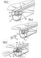
- FIGS. 1 to 6 the cover and one of its associated stiffening bars are shown in a position that is 180 ° inverted relative to the one they occupy when the cover is deployed on a pool .
- the covering sheet 1 is of the type commonly used as a pool cover.
- the present cover consists of a sheet 1 secured to a series of parallel and transverse stiffening bars 2.
- the section may be solid and / or made of plastic.
- the rigidifying bar 2 has a cross section in the general shape of "C", whose opening is turned upwards.
- the bar is made of two longitudinal walls 20 and 21.
- the outer wall has a generally "C" shaped cross section, while the second inner wall has a U-shaped cross section.
- This slot gives access to a longitudinal groove 27 delimited by the bottom 210 and wings 211 and 212 of the wall 21.
- the walls 24 and 25 are inclined and converge towards the slot 26.
- one of the ends of the outer wall 20 is interrupted. At this level is formed delimited by the closure wall 25 and one of the radial partitions 23, a groove 29 to which is accessed by a longitudinal slot 28.
- this groove is to accommodate means for powering the cover when the cover is deployed.
- this aspect does not constitute the core of the present invention, it will not be developed further.
- the cover according to the invention also makes use of a profile 3 in the general shape of an omega ( ⁇ ), also called a pinch profile, and in particular visible in FIGS. 1 to 6.
- omega also called a pinch profile
- This profile is for example made of polyvinyl chloride of a few millimeters thick, which gives it a certain rigidity in the longitudinal direction. Its length is identical to that of the bar 2 with which it is intended to cooperate.
- Its body 30 here has an approximately oval shape, and is symmetrical with respect to a vertical median plane. Its open ends extend to form the legs 31 and 32 of the omega.
- the inside of the body of this profile has been referenced 33. The latter is likely to deform elastically in the direction of the arrows g of Figure 2 so as to bring the lugs 31 and 32 above. However, in the absence of such a solicitation, this profile then immediately resumes its initial shape as shown in Figure 1.
- a first step is to position the cover 1 facing the slot 26 of one of the bars. We are then in the position of Figure 1. It is understood that the longitudinal flange 10 of the sheet extends perpendicular to the bar 2 shown.
- a gripping profile 3 is then grasped and introduced into the groove 27 of the bar 2, through the slot 26, in a movement generally perpendicular to the plane of the blanket, as shown by the arrow f .
- the cover 1 is partially driven inside the groove 27 by the profile 3, while the bulged portions 300 of the body 30 of the latter come to bear against the edges 240 and 250 of the slot 26. in doing so, these bulged parts are forced to move towards one another by elastic deformation, as shown by the arrows g of FIG.
- the body 30 then fully engages in the groove 27 and then resumes its initial position as illustrated in FIG.
- FIG. 4 Another element of the cover according to the invention is a rod 4 non-deformable longitudinally, shown in Figures 4 and 5.
- this section affects an approximately triangular section with a base 40 and two inclined walls 41.
- this ring is introduced inside the section 3 in a longitudinal movement illustrated by the arrow h .
- This ring has the function of opposing any deformation of the profile 3 positioned in the groove 27 and therefore to its removal from the bar, through the slot 26 of the latter.
- the assembly thus formed is completed by a sliding shoe 5 in the general shape of "T" with a foot 50 intended to engage partially inside the body of the clamping section 3, in the zone of separation of the legs 31 and 33, and a small trunk 51 terminated by a wide sliding surface 52 which extends to opposite ends of the closure walls 24 and 25.
- this sliding shoe consists of several unit sections, for example of a length of one meter, which are in turn fitted and positioned appropriately along the associated bar 2. It is through this sliding pad that the cover rests on the edge of a pool.
- Figure 6 also shows a plug 6 closing the opposite ends of the bar.
- This plug for example of hollow plastic, consists in particular of a body 60 whose shape is complementary to the section of the section which constitutes the bar.
- This body is extended by a projecting element 62 intended to engage partially in the profile, in the area between the two partitions 22 and 23, while preventing its unexpected withdrawal.
- a through hole 61 which is intended, as shown in Figure 7, the passage of a power cable 8 of the cover, which also cooperates with hems 7 to report to the cover.
- the structure thus formed is particularly practical to put in place. It does not require any screw or fastener of this type, which proves very practical in terms of assembly / disassembly.
- the stiffening bars 2 and their associated equipment can be reused.
- the cover when the cover is deployed on a pool such as a pool, the opposite ends of the bars 2 resting on the edge of two opposite sides of the pool, and in the event that a child is on the cover, the ring 4 opposes any deformation of the clamping section 3 and, consequently, its withdrawal from the bar.
- the cover thus retains its integrity, without risk of separation of the bars 2 and, consequently, of the child falling into the pool.
- This installation 9 comprises a support 90 of means 92 for immobilizing a rigidifying bar 2, such that the longitudinal groove 27 that it has opens upwards.
- the support 90 is surmounted by a thick plate 91, in which is formed a longitudinal channel which makes it possible to immobilize the bar 2.
- the installation also comprises a push blade 932 movable vertically and disposed vertically above said groove 27, adapted to engage in the body of the clamping profile 3 and force it to penetrate into said groove of the closed off.
- push blade is meant a longitudinal bar of restricted thickness.
- the blade is secured to displacement means which, in the case shown here, consist of double-acting cylinders 93 (only one is visible in Figure 8). There are enough jacks with respect to the length of the blade and they are controlled so that their rods 931 are moved in synchronism with respect to their body 930.
Landscapes
- Engineering & Computer Science (AREA)
- Architecture (AREA)
- Civil Engineering (AREA)
- Structural Engineering (AREA)
- Laminated Bodies (AREA)
- Sewage (AREA)
Claims (11)
- Abdeckung für ein Becken, wie ein Schwimmbad, die aus einer Abdeckplane (1) gebildet ist, die fest mit einer Reihe paralleler und querliegender Versteifungsstangen (2) verbunden ist, dadurch gekennzeichnet, dass:- die Versteifungsstangen (2) eine Längsauskehlung (27) umfassen, die durch einen Schlitz (26) nach außen mündet;- die Plane (1) partiell in die Auskehlung (27) eingeführt und zwischen diese und einem Profilteil (3) in allgemeiner Form eines Omega geklemmt ist - genannt Klemmprofilteil - dessen elastisch deformierbarer Körper (30) dimensioniert ist, um in der Ruhestellung wenigstens teilweise den Innenraum der Auskehlung (27) einzunehmen, und sich dessen Füße (31,32) dann auf die Außenseite der Ränder (240, 250) des Schlitzes abstützen,und dass sie einen nicht deformierbaren Haltestab (4) umfasst, der wenigstens teilweise das Innere (33) des Körpers (30) des Klemmprofilteils (3) einnimmt und der sich jeglicher Deformation des letztgenannten und folglich dessen Herausziehen aus der Stange (2) durch den Schlitz (26) hindurch durch elastische Deformation widersetzt.
- Abdeckung gemäß Anspruch 1, dadurch gekennzeichnet, dass das Klemmprofilteil (3) so angepasst ist, dass es die Deformation des Körpers (30) durch gegenseitige Annäherung seiner Füße (31,33) erlaubt.
- Abdeckung gemäß einem der Ansprüche 1 oder 2, dadurch gekennzeichnet, dass das Profilteil (3) aus Kunststoff, insbesondere aus Polyvinylchlorid ist.
- Abdeckung gemäß einem der vorhergehenden Ansprüche, dadurch gekennzeichnet, dass die Versteifungsstangen (2) aus hohlen Profilteilen bestehen, z.B. aus stranggepresstem Aluminium.
- Abdeckung gemäß einem der vorhergehenden Ansprüche, dadurch gekennzeichnet, dass die Versteifungsstangen (2) einen Querschnitt in allgemeiner Form eines "C" haben.
- Abdeckung gemäß einem der vorhergehenden Ansprüche, dadurch gekennzeichnet, dass die Versteifungsstangen (2) mit einer Gleitschiene (5) ausgestattet sind, die z.B. zwischen den Füßen (30,31) des Klemmprofilteils (3) geführt wird.
- Abdeckung gemäß Anspruch 6, dadurch gekennzeichnet, dass die Schiene (5) aus mehreren aneinandergrenzenden Teilstücken gebildet ist.
- Abdeckung gemäß einem der vorhergehenden Ansprüche, dadurch gekennzeichnet, dass die gegenüberliegenden Enden der Stangen (2) jedes mit einem Verschlussstopfen (6) ausgestattet sind.
- Verfahren zur Montage einer Abdeckung gemäß einem der Ansprüche 1 bis 8, dadurch gekennzeichnet, dass es insbesondere die folgenden aufeinanderfolgenden Schritte umfasst:- man positioniert die Plane (1) gegenüber des Schlitzes (26) einer der Stangen (2);- man führt das Klemmprofilteil (3) in die Auskehlung (27) durch den Schlitz (26) hindurch, gemäß einer Bewegung im allgemeinen senkrecht zur Ebene der Abdeckung, bis seine Füße (30,31) sich auf die Ränder (240,250) des Schlitzes abstützen;- man führt den Stab (4) in den Körper (30) des Profilteils (3) entlang einer Richtung parallel zum letztgenannten ein,- man wiederholt die vorhergehenden Tätigkeiten für jede Stange (2).
- Montageeinrichtung einer Abdeckung gemäß einem der Ansprüche 1 bis 8, dadurch gekennzeichnet, dass sie umfasst:- Mittel (92), um eine Versteifungsstange (2) so festzulegen, dass die Längsauskehlung (27), die sie umfasst, nach oben mündet;- eine in vertikaler Richtung bewegliche Drückerklinge (932), die im Lot zur Auskehlung (27) angeordnet ist und angepasst ist, in den Körper (30) des Klemmprofilteils (3) einzugreifen und dieses zu zwingen, in die Auskehlung (27) der Stange (1) einzudringen.
- Montageeinrichtung gemäß dem vorhergehenden Anspruch, dadurch gekennzeichnet, dass die Drückerklinge (932) fest mit Bewegungsmitteln (93), wie wenigstens einer Hubvorrichtung, verbunden ist.
Applications Claiming Priority (2)
| Application Number | Priority Date | Filing Date | Title |
|---|---|---|---|
| FR0401460A FR2866383B1 (fr) | 2004-02-13 | 2004-02-13 | Couverture pour un bassin tel qu'une piscine, procede et installation pour l'assemblage d'une telle couverture. |
| FR0401460 | 2004-02-13 |
Publications (2)
| Publication Number | Publication Date |
|---|---|
| EP1564346A1 EP1564346A1 (de) | 2005-08-17 |
| EP1564346B1 true EP1564346B1 (de) | 2007-04-11 |
Family
ID=34685021
Family Applications (1)
| Application Number | Title | Priority Date | Filing Date |
|---|---|---|---|
| EP20050364009 Expired - Lifetime EP1564346B1 (de) | 2004-02-13 | 2005-02-03 | Schwimmbadabdeckung, Verfahren und Einrichtung zum Zusammenbau einer solchen Abdeckung |
Country Status (3)
| Country | Link |
|---|---|
| EP (1) | EP1564346B1 (de) |
| DE (1) | DE602005000824D1 (de) |
| FR (1) | FR2866383B1 (de) |
Families Citing this family (1)
| Publication number | Priority date | Publication date | Assignee | Title |
|---|---|---|---|---|
| EP2116671A1 (de) * | 2008-05-06 | 2009-11-11 | Bieri Alpha Covers AG | Strebe für eine Schwimmbadabdeckung |
Family Cites Families (2)
| Publication number | Priority date | Publication date | Assignee | Title |
|---|---|---|---|---|
| US5107552A (en) * | 1990-05-03 | 1992-04-28 | Vogue Industries, Ltd. | Swimming pool cover and roll-up device |
| FR2690943B1 (fr) | 1992-05-11 | 1994-07-08 | Walter Ets Lucien | Dispositif enroulable de recouvrement d'un reservoir et notamment d'un bassin de piscine. |
-
2004
- 2004-02-13 FR FR0401460A patent/FR2866383B1/fr not_active Expired - Lifetime
-
2005
- 2005-02-03 EP EP20050364009 patent/EP1564346B1/de not_active Expired - Lifetime
- 2005-02-03 DE DE200560000824 patent/DE602005000824D1/de not_active Expired - Lifetime
Also Published As
| Publication number | Publication date |
|---|---|
| EP1564346A1 (de) | 2005-08-17 |
| DE602005000824D1 (de) | 2007-05-24 |
| FR2866383A1 (fr) | 2005-08-19 |
| FR2866383B1 (fr) | 2006-05-19 |
Similar Documents
| Publication | Publication Date | Title |
|---|---|---|
| EP2352925B1 (de) | Verfahren zur montage eines teiles auf einem profilstrang, vorrichtung zur zwischenbefestigung eines teiles auf einem profilstrang, verglasung und verwendung einer solchen vorrichtung | |
| CA2147092C (fr) | Capsule a vis pour le bouchage du goulot d'un recipient | |
| FR2889268A1 (fr) | Ensemble de fixation temporaire de deux elements, procede de montage d'une garniture interieure de portiere de vehicule et panneau de portiere realise selon ce procede de montage | |
| EP2882056B1 (de) | Rahmen für Einbaumontage einer Elektrodose in einer Wand und Montage eines solchen Rahmens mit einer Elektrodose . | |
| EP0294301B1 (de) | Vorrichtung zur zeitweiligen Verbindung der Enden von zwei Elementen, von denen mindestens eines biegsam ist | |
| EP0188986B1 (de) | Dose für teilweise einzugiessende Verbindungsstähle zwischen zwei Bauteilen | |
| EP0783928B1 (de) | Verfahren zum kreuzförmigen Eindrücken eines zumindest örtlich zylindrisch geformten Werkstückes in ein rohrförmiges Werkstück, dafür geeignetes Werkzeug sowie Verwendung des Werkzeuges | |
| EP1564346B1 (de) | Schwimmbadabdeckung, Verfahren und Einrichtung zum Zusammenbau einer solchen Abdeckung | |
| EP2406093B1 (de) | Profil für das abdeckelement einer ladefläche eines fahrzeugs und zugehöriges abdeckelement | |
| EP1309409B1 (de) | Befestigungselement für eine abgabevorrichtung | |
| EP1750974A1 (de) | Integrierte befestigungsklemme mit stiftbolzen, im besonderen zur verwendung für kraftfahrzeugkarosserieleisten | |
| FR2765606A1 (fr) | Poutrelle de support pour un caillebotis de piscine enterree | |
| EP2334513B1 (de) | Wickelvorrichtung, insbesondere für eine schutzblende, wie zum beispiel eine sonnenblende oder eine lastraumabdeckung | |
| EP1707706A1 (de) | Schalungsstück für Bauwerkselemente, wie z.B. die Stufen einer Treppe, insbesondere für ein Schwimmbad. | |
| EP1132290B1 (de) | Lukendeckel | |
| EP3115515B1 (de) | Schachtabdeckung mit einem rahmen und einem paneel | |
| EP1087485B1 (de) | Elektrischer Kabelkanal mit weichem Scharnier | |
| EP0943043A1 (de) | Wandelement mit einstellbarer krümmung für schwimmbecken | |
| FR3138278A1 (fr) | Dispositif annulaire pour œillet ou anneau de rideau | |
| FR3160721A1 (fr) | Coffre de volet roulant comprenant une structure longitudinale de renfort intérieure | |
| FR2729985A1 (fr) | Structure d'installation generale a mise en place de panneaux de cloison facilitee | |
| FR2946557A1 (fr) | Procede de mise en place d'un joint souple filant dans une rainure de profile, et outil permettant une mise en oeuvre du procede | |
| FR2997116A1 (fr) | Mannequin pour la fabrication d'ouverture dans du beton coule | |
| FR2842233A1 (fr) | Caisson de reservation pour armatures de liaison | |
| FR2902159A1 (fr) | Dispositif d'ancrage a chevilles a ailettes |
Legal Events
| Date | Code | Title | Description |
|---|---|---|---|
| PUAI | Public reference made under article 153(3) epc to a published international application that has entered the european phase |
Free format text: ORIGINAL CODE: 0009012 |
|
| AK | Designated contracting states |
Kind code of ref document: A1 Designated state(s): AT BE BG CH CY CZ DE DK EE ES FI FR GB GR HU IE IS IT LI LT LU MC NL PL PT RO SE SI SK TR |
|
| AX | Request for extension of the european patent |
Extension state: AL BA HR LV MK YU |
|
| 17P | Request for examination filed |
Effective date: 20050920 |
|
| AKX | Designation fees paid |
Designated state(s): BE CH DE ES FR LI |
|
| GRAP | Despatch of communication of intention to grant a patent |
Free format text: ORIGINAL CODE: EPIDOSNIGR1 |
|
| GRAS | Grant fee paid |
Free format text: ORIGINAL CODE: EPIDOSNIGR3 |
|
| GRAA | (expected) grant |
Free format text: ORIGINAL CODE: 0009210 |
|
| AK | Designated contracting states |
Kind code of ref document: B1 Designated state(s): BE CH DE ES FR LI |
|
| REG | Reference to a national code |
Ref country code: CH Ref legal event code: EP |
|
| REF | Corresponds to: |
Ref document number: 602005000824 Country of ref document: DE Date of ref document: 20070524 Kind code of ref document: P |
|
| PG25 | Lapsed in a contracting state [announced via postgrant information from national office to epo] |
Ref country code: ES Free format text: LAPSE BECAUSE OF FAILURE TO SUBMIT A TRANSLATION OF THE DESCRIPTION OR TO PAY THE FEE WITHIN THE PRESCRIBED TIME-LIMIT Effective date: 20070722 |
|
| PLBE | No opposition filed within time limit |
Free format text: ORIGINAL CODE: 0009261 |
|
| REG | Reference to a national code |
Ref country code: CH Ref legal event code: NV Representative=s name: MICHELI & CIE SA |
|
| STAA | Information on the status of an ep patent application or granted ep patent |
Free format text: STATUS: NO OPPOSITION FILED WITHIN TIME LIMIT |
|
| 26N | No opposition filed |
Effective date: 20080114 |
|
| PG25 | Lapsed in a contracting state [announced via postgrant information from national office to epo] |
Ref country code: DE Free format text: LAPSE BECAUSE OF FAILURE TO SUBMIT A TRANSLATION OF THE DESCRIPTION OR TO PAY THE FEE WITHIN THE PRESCRIBED TIME-LIMIT Effective date: 20070712 |
|
| PG25 | Lapsed in a contracting state [announced via postgrant information from national office to epo] |
Ref country code: BE Free format text: LAPSE BECAUSE OF NON-PAYMENT OF DUE FEES Effective date: 20150228 |
|
| REG | Reference to a national code |
Ref country code: FR Ref legal event code: PLFP Year of fee payment: 12 |
|
| PGFP | Annual fee paid to national office [announced via postgrant information from national office to epo] |
Ref country code: CH Payment date: 20160208 Year of fee payment: 12 |
|
| REG | Reference to a national code |
Ref country code: FR Ref legal event code: PLFP Year of fee payment: 13 |
|
| REG | Reference to a national code |
Ref country code: CH Ref legal event code: PL |
|
| PG25 | Lapsed in a contracting state [announced via postgrant information from national office to epo] |
Ref country code: LI Free format text: LAPSE BECAUSE OF NON-PAYMENT OF DUE FEES Effective date: 20170228 Ref country code: CH Free format text: LAPSE BECAUSE OF NON-PAYMENT OF DUE FEES Effective date: 20170228 |
|
| REG | Reference to a national code |
Ref country code: FR Ref legal event code: PLFP Year of fee payment: 14 |
|
| PGFP | Annual fee paid to national office [announced via postgrant information from national office to epo] |
Ref country code: FR Payment date: 20230113 Year of fee payment: 19 |
|
| PGFP | Annual fee paid to national office [announced via postgrant information from national office to epo] |
Ref country code: BE Payment date: 20230220 Year of fee payment: 19 |
|
| REG | Reference to a national code |
Ref country code: BE Ref legal event code: MM Effective date: 20240229 |
|
| PG25 | Lapsed in a contracting state [announced via postgrant information from national office to epo] |
Ref country code: BE Free format text: LAPSE BECAUSE OF NON-PAYMENT OF DUE FEES Effective date: 20240229 |
|
| PG25 | Lapsed in a contracting state [announced via postgrant information from national office to epo] |
Ref country code: FR Free format text: LAPSE BECAUSE OF NON-PAYMENT OF DUE FEES Effective date: 20240229 |
|
| PG25 | Lapsed in a contracting state [announced via postgrant information from national office to epo] |
Ref country code: FR Free format text: LAPSE BECAUSE OF NON-PAYMENT OF DUE FEES Effective date: 20240229 Ref country code: BE Free format text: LAPSE BECAUSE OF NON-PAYMENT OF DUE FEES Effective date: 20240229 |