EP1564323B1 - Tür für eine Trommelwaschmaschine - Google Patents
Tür für eine Trommelwaschmaschine Download PDFInfo
- Publication number
- EP1564323B1 EP1564323B1 EP20050002530 EP05002530A EP1564323B1 EP 1564323 B1 EP1564323 B1 EP 1564323B1 EP 20050002530 EP20050002530 EP 20050002530 EP 05002530 A EP05002530 A EP 05002530A EP 1564323 B1 EP1564323 B1 EP 1564323B1
- Authority
- EP
- European Patent Office
- Prior art keywords
- door frame
- door
- grip
- hook
- hole
- Prior art date
- Legal status (The legal status is an assumption and is not a legal conclusion. Google has not performed a legal analysis and makes no representation as to the accuracy of the status listed.)
- Expired - Lifetime
Links
- 238000005406 washing Methods 0.000 title claims description 45
- 239000011521 glass Substances 0.000 claims description 30
- 238000003780 insertion Methods 0.000 claims description 20
- 230000037431 insertion Effects 0.000 claims description 20
- 239000000463 material Substances 0.000 claims description 11
- 238000007747 plating Methods 0.000 claims description 9
- 238000010276 construction Methods 0.000 description 7
- 238000004519 manufacturing process Methods 0.000 description 4
- 238000000034 method Methods 0.000 description 4
- 239000002991 molded plastic Substances 0.000 description 4
- 230000000694 effects Effects 0.000 description 3
- 239000007769 metal material Substances 0.000 description 3
- VYZAMTAEIAYCRO-UHFFFAOYSA-N Chromium Chemical compound [Cr] VYZAMTAEIAYCRO-UHFFFAOYSA-N 0.000 description 2
- 238000001035 drying Methods 0.000 description 2
- 230000002093 peripheral effect Effects 0.000 description 2
- 239000012780 transparent material Substances 0.000 description 2
- 230000008878 coupling Effects 0.000 description 1
- 238000010168 coupling process Methods 0.000 description 1
- 238000005859 coupling reaction Methods 0.000 description 1
- 239000003599 detergent Substances 0.000 description 1
- 230000005484 gravity Effects 0.000 description 1
- 238000010412 laundry washing Methods 0.000 description 1
- 238000007789 sealing Methods 0.000 description 1
- 239000007779 soft material Substances 0.000 description 1
- XLYOFNOQVPJJNP-UHFFFAOYSA-N water Substances O XLYOFNOQVPJJNP-UHFFFAOYSA-N 0.000 description 1
Images


Classifications
-
- D—TEXTILES; PAPER
- D06—TREATMENT OF TEXTILES OR THE LIKE; LAUNDERING; FLEXIBLE MATERIALS NOT OTHERWISE PROVIDED FOR
- D06F—LAUNDERING, DRYING, IRONING, PRESSING OR FOLDING TEXTILE ARTICLES
- D06F37/00—Details specific to washing machines covered by groups D06F21/00 - D06F25/00
- D06F37/02—Rotary receptacles, e.g. drums
- D06F37/04—Rotary receptacles, e.g. drums adapted for rotation or oscillation about a horizontal or inclined axis
- D06F37/10—Doors; Securing means therefor
-
- D—TEXTILES; PAPER
- D06—TREATMENT OF TEXTILES OR THE LIKE; LAUNDERING; FLEXIBLE MATERIALS NOT OTHERWISE PROVIDED FOR
- D06F—LAUNDERING, DRYING, IRONING, PRESSING OR FOLDING TEXTILE ARTICLES
- D06F37/00—Details specific to washing machines covered by groups D06F21/00 - D06F25/00
- D06F37/02—Rotary receptacles, e.g. drums
- D06F37/04—Rotary receptacles, e.g. drums adapted for rotation or oscillation about a horizontal or inclined axis
- D06F37/06—Ribs, lifters, or rubbing means forming part of the receptacle
-
- D—TEXTILES; PAPER
- D06—TREATMENT OF TEXTILES OR THE LIKE; LAUNDERING; FLEXIBLE MATERIALS NOT OTHERWISE PROVIDED FOR
- D06F—LAUNDERING, DRYING, IRONING, PRESSING OR FOLDING TEXTILE ARTICLES
- D06F37/00—Details specific to washing machines covered by groups D06F21/00 - D06F25/00
- D06F37/26—Casings; Tubs
- D06F37/261—Tubs made by a specially selected manufacturing process or characterised by their assembly from elements
-
- D—TEXTILES; PAPER
- D06—TREATMENT OF TEXTILES OR THE LIKE; LAUNDERING; FLEXIBLE MATERIALS NOT OTHERWISE PROVIDED FOR
- D06F—LAUNDERING, DRYING, IRONING, PRESSING OR FOLDING TEXTILE ARTICLES
- D06F37/00—Details specific to washing machines covered by groups D06F21/00 - D06F25/00
- D06F37/26—Casings; Tubs
- D06F37/28—Doors; Security means therefor
-
- D—TEXTILES; PAPER
- D06—TREATMENT OF TEXTILES OR THE LIKE; LAUNDERING; FLEXIBLE MATERIALS NOT OTHERWISE PROVIDED FOR
- D06F—LAUNDERING, DRYING, IRONING, PRESSING OR FOLDING TEXTILE ARTICLES
- D06F39/00—Details of washing machines not specific to a single type of machines covered by groups D06F9/00 - D06F27/00
- D06F39/12—Casings; Tubs
- D06F39/14—Doors or covers; Securing means therefor
-
- Y—GENERAL TAGGING OF NEW TECHNOLOGICAL DEVELOPMENTS; GENERAL TAGGING OF CROSS-SECTIONAL TECHNOLOGIES SPANNING OVER SEVERAL SECTIONS OF THE IPC; TECHNICAL SUBJECTS COVERED BY FORMER USPC CROSS-REFERENCE ART COLLECTIONS [XRACs] AND DIGESTS
- Y10—TECHNICAL SUBJECTS COVERED BY FORMER USPC
- Y10T—TECHNICAL SUBJECTS COVERED BY FORMER US CLASSIFICATION
- Y10T292/00—Closure fasteners
- Y10T292/08—Bolts
- Y10T292/0801—Multiple
- Y10T292/0825—Hooked end
- Y10T292/0826—Operating means
- Y10T292/0831—Lever
Definitions
- the present invention relates to a door of a drum type washing machine having a hook assembly for locking the door, and, more particularly, to a door of a drum type washing machine that allows a hook assembly to be easily and conveniently mounted to the door and that is capable of preventing the pleasing appearance of the door from being spoiled due to a handle of the hook assembly.
- a drum type washing machine is a machine that washes the laundry using friction generated between a drum rotated by a driving force of a motor and the laundry while detergent, wash water, and the laundry are put in the drum, which is horizontally disposed.
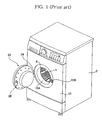
- FIG. 1 is a perspective view illustrating a conventional drum type washing machine.
- the conventional drum type washing machine comprises: a cabinet 2 forming the appearance of the drum type washing machine; a tub (not shown) horizontally disposed in the cabinet 2; a drum 4 rotatably disposed in the tub for washing the laundry; a plurality of lifting blades 6 attached to the inner circumferential surface of the drum 4 for lifting the laundry to a predetermined height such that the laundry drops from the lifting blades by gravity at the predetermined height; a motor 8 disposed at the rear of the tub for generating a driving force necessary to drive the drum 4; a cabinet cover 10 attached to the front part of the cabinet 2, the cabinet cover 20 being provided at the center thereof with a laundry inlet/outlet hole 10A for allowing the laundry to be put into or removed from the drum 4 therethrough; and a door 20 attached to the cabinet cover 10 for opening and closing the laundry inlet/outlet hole 10A.
- one lateral side of the door 20 is hingedly connected to the cabinet cover 10 by means of a door hinge 24, and at the other lateral side of the door 20 is disposed a hook assembly 28 for locking the door 20 to the cabinet cover 10 to prevent the door 20 from being accidentally opened.
- the hook assembly 28 is inserted in a locking fashion into a hook hole 10B formed at the cabinet cover 10.
- the hook assembly 28 may be a handle type hook assembly or a non-handle type hook assembly.
- the handle type hook assembly has a handle, which is manipulated by a user of the drum type washing machine. In the handle type hook assembly, the door 20 is locked or unlocked through the user's manual manipulation of the handle.
- the non-handle type hook assembly has an additional locking mechanism (not shown), which is disposed at the hook hole side of the cabinet cover 10. In the non-handle type hook assembly, the door 20 is automatically locked or unlocked by the locking mechanism based on operations of the drum type washing machine.
- the handle type hook assembly Since the door 10 is manually locked or unlocked through the user's manual manipulation of the handle in the case of the handle type hook assembly, on the other hand, it is easy to manufacture the hook assembly as compared to the non-handle type hook assembly, and the hook assembly can be economically manufactured.
- the handle type hook assembly has problems in that the appearance of the door 20 is not pleasing due to the presence of the handle and in that it is very difficult to mount the hook assembly to the door 20.
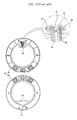
- FIG. 2 is a perspective view illustrating one example of a conventional door 20 having a handle type hook assembly
- FIG. 3 is an exploded plan view illustrating a door frame of the door 20 shown in FIG. 2 .
- the conventional door 20 comprises: a ring-shaped door frame 22 hingedly connected to the front surface of the cabinet cover 10 at one lateral side thereof; a door hinge 24 (See FIG. 1 ), having both ends attached to one lateral side of the door frame 22 and the front cover of the cabinet cover 10, respectively, for hingedly supporting the door frame 22; a door glass 26 disposed at the center, which is opened, of the door frame 22; and a hook assembly 28 disposed at the other lateral side of the door frame 22 such that the hook assembly 28 is inserted in a locking fashion into a hook hole 10B formed at the front surface of the cabinet cover 10.
- the door frame 22 is made of an injection-molded plastic material.
- the door frame 22 comprises: a front door frame part 30; and a rear door frame part 32 disposed at the rear surface of the front door frame part 30.
- a grip part 34 At one lateral side of the inner circumferential surface of the front door frame part 30 is formed a grip part 34, which is protruded inward such that the grip part 34 is gripped by a user of the drum type washing machine when the door 20 is opened or closed.
- an opening hole 31 At the inner circumferential surface of the front door frame part 30, which is opposite to the rear of the grip part 34, is formed an opening hole 31.
- the edge of the door glass 26 is fixedly disposed between the front door frame part 30 and the rear door frame part 32 for hermetically sealing the opened center of the door frame 22.
- the hook assembly 28 comprises: a hook 40 extending through the rear door frame part 32; a hook shaft 42, to which the hook 40 is hingedly attached, the hook shaft 42 having both ends respectively supported by supporting parts 36 formed at the front surface of the rear door frame part 32; a handle 44 having one lateral side hingedly attached to the hook shaft 42 and the other lateral side disposed at the rear of the grip part 34; and resilient members 46 disposed on the hook shaft 42 for resiliently supporting the hook 40.
- a through-hole 38 through which the hook 40 is inserted.
- a hook hole 10B which corresponds to the hook 40. The hook 40 is inserted in a locking fashion into the hook hole 10B such that the hook 40 is locked.
- the handle 44 is inserted through the opening hole 31 of the front door frame part 30.
- the hook 40 is moved in a hinged fashion in the lateral direction of the drum type washing machine.
- the resilient members 46 are coil springs disposed on the hook shaft 42.
- the inner ends of the resilient members 46 are held at both sides of the hook 40, respectively, and the outer ends of the resilient members 46 are held at the rear surface of the front door frame part 30.
- the hook assembly 28 is mounted to the rear door frame part 32, and then the front door frame part 30 is securely fixed to the front surface of the rear door frame part 32 by means of a fixing member.
- the edge of the door glass 26 is disposed between the inner circumferential parts of the front door frame part 30 and the rear door frame part 32, and therefore, the door glass 26 is securely fixed by the front door frame part 30 and the rear door frame part 32.
- the outer ends of the resilient members 46 of the hook assembly 28 are pressed by the front door frame part 30, and therefore, resilient forces are provided to the hook 40.
- the door frame 22 is hingedly connected to the cabinet cover 10 by the door hinge 24 at one lateral side thereof.
- the grip part 34 is protruded inward from the inner circumferential surface of the front door frame part 30 such that the handle 44 of the hook assembly 28 is hidden and the grip part 34 is held by the user of the drum type washing machine.
- the door frame 22 is not formed in the shape of a complete ring due to the grip part 34, and therefore, the pleasing appearance of the door 20 is spoiled.
- the front door frame part 30 is securely fixed to the front surface of the rear door frame part 32 by means of the fixing member while the door hinge 24, the hook assembly 28, and the door glass 26 are disposed at the rear door frame part 32.
- the assembling process of the door frame 22 is very difficult, and the hook assembly 28 may be incorrectly assembled.
- the hook shaft 42 When the door frame 22 is assembled, for example, the hook shaft 42 may be accidentally separated from the door frame 22, or the outer ends of the resilient members 46 may not be correctly held at the rear surface of the front door frame part 30. For this reason, it is necessary to securely fix the front door frame part 30 to the front surface of the rear door frame part 32 while the hook assembly 28 is properly held. Consequently, the assembling process of the door frame 22 is very difficult.
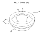
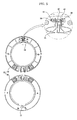
- FIG. 4 is a perspective view illustrating another example of a conventional door 21 having a handle type hook assembly
- FIG. 5 is an exploded plan view illustrating a door frame of the door 21 shown in FIG. 4 .
- a grip hole 35 is formed at the inner circumferential surface of the front door frame part 30 such that the user of the drum type washing machine can hold the grip hole 35 to open or close the door 21.
- the hook assembly 29, including the handle 45, is disposed inside the grip hole 35.
- Other construction of the conventional door 21 shown in FIGS. 4 and 5 is identical to that of the conventional door 20 shown in FIGS. 2 and 3 .
- One end of the handle 45 is hingedly attached to the hook shaft 42, and the other end of the handle 45 is disposed in the grip hole 35 such that the hook 40 is moved in a hinged fashion in the lateral direction of the drum type washing machine through the user's manipulation.
- the handle 45 is not protruded out of the grip hole 35, and the front door frame part 30 is formed in the shape of a complete ring. Consequently, the pleasing appearance of the door 21 is not spoiled as shown in FIGS. 4 and 5 , which is distinguished from the conventional door 20 shown in FIGS. 2 and 3 , in which the pleasing appearance of the door 20 is spoiled due to the handle 44 and the grip part 34.
- the hook assembly 29, including the handle 45 is disposed in the door frame 22, at which the grip hole 35 is formed.
- the interiors of the front door frame part 30 and the rear door frame part 32 are exposed to the outside through the grip hole 35, which affects the pleasing appearance of the door 21, and therefore, marketability of the drum type washing machines having such doors is lowered.
- the door frame 30 is made of an injection-molded plastic material, which does not provide high quality and luxurious appearance to the consuming public.
- the rear door frame part 32 which is not exposed to the outside, is not plated, although the surface of the front door frame part 30 is plated with a metal material to improve the pleasing appearance and surface hardness of the front door frame part 30. Consequently, the unplated front surface of the rear door frame part 32 and the complicated components in the door frame 22 are exposed to the outside through the grip hole 35, and therefore, the pleasing appearance of the door 21 is spoiled.
- WO 03/004754 A1 describes a washing machine door.
- the laundry washing and/or drying machine of a front loading type comprises a door on the front panel through which a user performs the loading/unloading operations of the laundry.
- the door consists of an inner frame, an outer frame and a window preferably made of a transparent material, for instance glass, that is placed between these two frames.
- the door comprises a locking mechanism, which comprises a handle, a lock performing the locking function and a hook cover.
- a recess on which the hook cover is attached is provided on the inner frame.
- a projection providing the fixation of the window at a desired position is located adjacent to the hook cover. The projection is so designed that it can fit into a socket provided on the lateral surface of the window between the inner and outer frames, when the hook cover is attached to the recess.
- GB 2 320 507 A describes a door for a washing machine and/or drying machine.
- a door comprises a central part in the form of a porthole, produced of glass or other transparent material, and a peripheral flange which extends around the periphery of the central part.
- the flange carries one of the two components of a hinge system for the door while on the right-hand side it carries a pin of a handle for opening and closing the door.
- the door further comprises a frame of angular shape, which extends over the peripheral flange in such a way as to hide it from view, leaving a free space in its interior. The free space permits pivotal movement of the handle about the pin during opening and closing of the door.
- a hollow cover element is provided, which is made of a soft material.
- the present invention has been made in view of the above problems, and it is an object of the present invention to provide a door of a drum type washing machine that allows a hook assembly to be easily and conveniently mounted inside a door frame and that allows the hook assembly to be disposed inside a grip hole of the door frame, thereby preventing the pleasing appearance of the door from being spoiled.
- the front door frame is provided at the rear surface thereof with a fixing boss, which communicates with the fixing hole of the front door frame
- the grip casing is provided with a boss insertion part, which communicates with the fixing hole of the grip casing such that the fixing boss of the front door frame is inserted into the boss insertion part.
- the grip casing is provided at the inside part of the rear surface thereof with supporting parts for supporting both ends of the hook shaft, respectively.
- the supporting parts comprise: a first supporting part for supporting one end of the hook shaft; and a second supporting part for supporting the other end of the hook shaft, the insertion hole being formed between the first supporting part and the second supporting part.
- the interiors of the front door frame and the rear door frame are prevented from being exposed to the outside through the grip hole by the grip casing and the hook assembly is easily and conveniently mounted to the door frame.
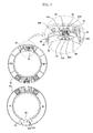
- FIG. 6 is a perspective view illustrating a door 50 of a drum type washing machine according to a first preferred embodiment of the present invention
- FIG. 7 is an exploded plan view illustrating a door frame of the door 50 shown in FIG. 6
- FIG. 8 is a sectional view taken along the line A-A of FIG. 6
- FIG. 9 is a perspective view, partially cutaway, illustrating principal components of the door 50 shown in FIG. 8
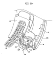
- FIG. 10 is a perspective view, partially cutaway, illustrating assembly of the principal components of the door 50 shown in FIG. 8
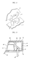
- FIG. 11 is an exploded perspective view illustrating a locking protrusion and a locking part of the door 50 shown in FIG. 10 .
- the door 50 comprises: a ring-shaped rear door frame 52 forming the rear surface of the door 50; a ring-shaped front door frame 54 attached to the front surface of the rear door frame 52, the front door frame 54 being provided at the inner circumferential surface thereof with a grip hole 58; a door glass 56 disposed at open centers of the front door frame 54 and the rear door frame 52, respectively, the door glass 56 having the edge securely fixed by the front door frame 54 and the rear door frame 52; a grip casing 60 mounted inside the grip hole 58 for preventing the interiors of the front door frame 54 and the rear door frame 52 from being exposed to the outside through the grip hole 58; and a hook assembly 80 disposed through the grip casing 60 for locking the front door frame 54 and the rear door frame 52 to the cabinet cover 10.
- the front door frame 54 and the rear door frame 52 are made of an injection-molded plastic material.
- the front door frame 54 which forms the front surface of the door 50, is plated with a metal material to improve the pleasing appearance of the front door frame 54.
- chrome is typically used as a plating material for the front door frame 54.
- a plating layer made of chrome is formed on the surface of the front door frame 54, the surface hardness of the front door frame 54 is improved while the front door frame 54 provides metal material feel and brilliance.
- One lateral side of the front door frame 54 and one lateral side of the rear door frame 52 are hingedly connected to the cabinet cover by a door hinge.
- the hook assembly 80 is disposed at the other-lateral side of the front door frame 54 and the other lateral side of the rear door frame 52 for selectively locking the door 50 to the cabinet cover.
- a grip hole 58 for allowing a user of the drum type washing machine to hold when opening or closing the door 50.
- the edge of the door glass 56 is disposed between the front door frame 54 and the rear door frame 52.
- the front door frame 54 is securely fixed to the rear door frame 52 by means of a fixing member (not shown)
- the door glass 56 is disposed at the open centers of the front door frame 54 and the rear door frame 52 while being hermetically sealed.
- the front door frame 54 and the rear door frame 52 are provided with pluralities of fixing holes 54B and 52B in the circumferential direction thereof while the fixing holes 54B formed at the front door frame 54 correspond to the fixing holes 52B formed at the rear door frame 52, respectively. While the drum type washing machine is operated, the interior of the drum can be seen through the door glass 56 from the outside.
- the grip casing 60 is formed in the shape of a box having an open front part. At the inner part of the grip casing 60 is formed an opening 62.
- the grip casing 60 is attached to the rear surface of the front door frame 54 such that the opening 62 of the grip casing 60 communicates with the grip hole 58 of the front door frame 54.
- the opening 62 of the grip casing 60 has a size equal to or greater than that of the grip hole 58 of the front door frame 54.
- the grip casing 60 is made of an injection-molded plastic material, and the surface of the grip casing 60 is plated with the same material as the plating material for the front door frame 54.
- the grip casing 60 forms the interior of the grip hole 58 together with the front door frame 54.
- the grip casing 60 is provided at both sides thereof with a plurality of locking protrusions 66, which are inserted in a locking fashion into a plurality of locking parts 64 formed at the rear surface of the front door frame 54, respectively.
- the locking parts 64 are protruded in the shape of a plate from the rear surface of the front door frame 54, to which the grip casing 60 is attached. At the centers of the locking parts 64 are formed locking holes 64A, into which the locking protrusions 66 are inserted in a locking fashion, respectively.
- the locking parts 64 come into tight contact with the sides of the grip casing 60 when the grip casing 60 is attached to the front door frame 54. Consequently, the locking parts 64 serve to maintain positions where the grip casing 60 is attached are maintained and to guide the movement of the grip casing 60 when the grip casing 60 is attached to the front door frame 54.
- both sides of the grip casing 60 are also formed guide ribs 68 for guiding the insertion of the locking protrusions 66 into the locking parts 64 such that the locking protrusions 66 are exactly inserted in a locking fashion into the locking parts 64, respectively.
- the guide ribs 68 are formed at the left and right sides of each of the locking protrusions 66 while the guide ribs 68 are in tight contact with both side ends of each of the locking parts 64, respectively.
- the rear surface of the grip casing 60 is in tight contact with the front surface of the rear door frame 52, at which the edge of the door glass 56 is located.
- the grip casing 60 is provided at the center of the rear surface thereof with an insertion hole 60A, through which the hook assembly 80 is disposed.
- a locating rib 70 for locating the door glass 56.
- a through-hole 52A which communicates with the insertion hole 60A such that the hook assembly 80 is inserted through the through-hole 52A.
- the locating rib 70 is protruded from the outside part of the rear surface of the grip casing 60 such that the locating rib 70 surrounds the edge of the door glass 56 for locating the door glass 56.
- a fixing rib 72 which is spaced apart from the locating rib 70 for securely fixing the edge of the door glass 56.
- the fixing rib 72 is protruded while being spaced apart a predetermined distance from the door glass 56 toward the locating rib 70. Consequently, the fixing rib 72 securely fixes the edge of the door glass 56 by the coupling force between the front door frame 54 and the rear door frame 52.
- the front door frame 54 and the rear door frame 52 are provided at the positions corresponding to the positions where the locating rib 70 and the fixing rib 72 are formed with structural members corresponding to the locating rib 70 and the fixing rib 72, respectively.
- At the rear surface of the grip casing 60 is formed at least one fixing hole 73, which communicates with the fixing holes 54B and 52B of the front door frame 54 and the rear door frame 52.
- the fixing member engaged into the fixing holes 54B and 52B of the front door frame 54 and the rear door frame 52 are also engaged into the fixing hole 73, and therefore, the grip casing 60 is more securely mounted inside the front door frame 54 and the rear door frame 52.
- a fixing boss 54A which communicates with the fixing hole 54B of the front door frame 54.
- the fixing boss 54A is protruded rearward.
- a boss insertion part 74 which communicates with the fixing hole 54B of the front door frame 54 and the fixing hole 73 of the grip casing 60 such that the fixing boss 54A of the front door frame 54 is inserted into the boss insertion part 74.
- the grip casing 60 is attached to the rear surface of the front door frame 54 such that the fixing boss 54A is inserted into the boss insertion part 74, the grip casing 60 is properly located by means of the boss insertion part 74 and the fixing boss 54A, and therefore, the grip casing 60 is more stably attached to the rear surface of the front door frame 54.
- the hook assembly 80 comprises: a hook 82 disposed through the insertion hole 60A of the grip casing 60 and the through-hole 52A of the rear door frame 52, the hook 82 having one end inserted in a locking fashion into the hook hole of the cabinet cover; a hook shaft 84, to which the other end of the hook 82 is hingedly attached, the hook shaft 84 having both ends respectively supported by supporting parts 76 formed at the inside part of the rear surface of the grip casing 60; a handle 86, having one end hingedly attached to the hook shaft 84 and the other end disposed at the grip hole 58, for moving the hook 82 in a hinged fashion; and resilient members 88, each having both ends disposed at the hook 82 and the front door frame 54, respectively, for resiliently supporting the hook 82.
- the insertion hole 60A of the grip casing 60 and the through-hole 52A of the rear door frame 52 have sufficient sizes in the lateral direction of the drum type washing machine, respectively, such that the hook 82 can be moved in a hinged fashion in the lateral direction of the drum type washing machine by the handle 86.
- the supporting parts 76 are formed above and below the insertion hole 60A of the grip casing 60.
- the supporting parts 76 comprise: a first supporting part 76A disposed above the insertion hole 60A for supporting one end of the hook shaft 84; and a second supporting part 76B disposed below the insertion hole 60A for supporting the other end of the hook shaft 84.
- the handle 86 is provided at one side thereof with a fitting hole 86A, through which one end of the hook 82 is fitted.
- the handle 86 is provided at the other side thereof with a grip part 86B, which is disposed inside the grip hole 58 such that the grip part 86B is manipulated by the user of the drum type washing machine.
- the handle 86 is moved in a hinged fashion about the hook shaft 84, and therefore, the hook 82 is moved in the lateral direction of the drum type washing machine while being inserted in a locking fashion through the fitting hole 86A.
- the resilient members 88 are coil springs wound on the hook shaft 84.
- the inner ends of the resilient members 88 are held at the left and right side surfaces of the hook 84, respectively, and the outer ends of the resilient members 88 are held at the rear surface of the front door frame part 54.
- the resilient members 88 are disposed on the hook shaft 84, the inner ends of the resilient members 88 are held at the hook 82, and the outer ends of the resilient members 88 are pressed by the front door frame part 54 as the grip casing 60 is attached to the rear surface of the front door frame 54, and therefore, resilient forces are provided to the hook 82.
- both ends of the hook shaft 84 are fixed to the first and second supporting parts 76A and 76B of the grip casing 60.
- one end of the hook 82 is disposed through the insertion hole 60A of the grip casing 60, and the grip part 86B of the handle 86 is disposed at the opening 62 of the grip casing 60.
- the grip casing 60 is attached to the rear surface of the front door frame 54 such that the opening 62 of the grip casing 60 communicates with the grip hole 58 of the front door frame 54.
- the grip casing 60 is located between the locking parts 64 formed at the rear surface of the front door frame 54 such that the locking parts 64 come into tight contact with the side surfaces of the grip casing 60, and the locking protrusions 66 formed at the sides of the grip casing 60 are guided into the locking holes 64A of the locking parts 64 by the guide ribs, and therefore, the locking protrusions 66 are inserted in a locking fashion into the locking holes 64A, respectively.
- the edge of the door glass 56 is located at the inner circumferential surface of the rear door frame 52.
- the front door frame 54 is attached to the front surface of the rear door frame 52.
- the edge of the door glass 56 is securely fixed by the front door frame 54 and the rear door frame 52, and the edge of the door glass 56 and the rear door frame 52 come into tight contact with the rear surface of the grip casing 60.
- the door glass 56 is properly located by the locating rib 70 of the grip casing 60, and the edge of the door glass 56 is securely fixed to the rear door frame 52 by the fixing rib 72 of the grip casing 60.
- the front door frame 54 is securely fixed to the rear door frame 52 by engaging the fixing member into the fixing holes 54B and 52B.
- Another fixing member is inserted through the fixing hole 73 of the grip casing 60 to securely fix the grip casing 60.
- the other end of the door hinge is connected to the front surface of the cabinet cover. In this way, the door 50 is attached to the drum type washing machine.
- the door 50 with the above-stated construction is operated as follows: when a user pushes the handle 86 of the hook assembly 80, disposed in the grip hole 58, forward, the hook 82 is moved in a hinged fashion by the handle 86, and therefore, the locked state of the door 50 is released. The door 50 is moved in a hinged fashion in the lateral direction of the drum type washing machine by the user holding the grip hole 58, and therefore, the laundry inlet/outlet hole of the cabinet cover is opened or closed.
- the hook 82 is returned to its original state by the resilient members 88 while being inserted in the hook hole of the cabinet cover. As a result, the hook 82 is caught in the hook hole of the cabinet cover, and therefore, the door 50 is locked.
- the interiors of the front door frame 54 and the rear door frame 52 are exposed to the outside through the grip hole 58.
- the grip casing 60 is mounted inside the grip hole 58, and the surface of the grip casing 60 is plated with the same material as the plating material for the front door frame 54.
- the grip casing 60 is mounted inside the grip hole 58, and the surface of the grip casing 60 is plated with the same material as the plating material for the front door frame 54.
- FIG. 12 is a sectional view illustrating a hook assembly disposed in a door of a drum type washing machine according to a second preferred embodiment of the present invention.
- a casing cover 61 is additionally disposed at the open front part of the grip casing 60.
- the casing cover 61 is attached to the rear surface of the front door frame 54 while being in tight contact with the rear surface of the front door frame 54.
- Other construction of the second preferred embodiment is identical to that of the first preferred embodiment.
- the grip casing 60 is formed in the shape of a box having an open front part.
- the hook assembly 80 is mounted in the grip casing 60, and then the casing cover 61 is disposed at the front part of the grip casing 60.
- the inner ends of the resilient members 88 of the hook assembly 80 are held at the hook 82, and the outer ends of the resilient members 88 of the hook assembly 80 are pressed by the casing cover 61. Consequently, resilient forces are provided to the hook 82.
- the grip casing 60, the hook assembly 80, and the casing cover 61 can be provided as a single module, which is easily and conveniently attached to the rear surface of the front door frame 54. Consequently, components of the door can be easily charged and handled.
- the grip casing is mounted to the rear surface of the front door frame such that the grip casing communicates with the grip hole, and the hook assembly is disposed inside the grip casing. Consequently, the present invention has the effect of preventing the interiors of the front door frame and the rear door frame from being exposed to the outside through the grip hole by the grip casing and allowing the hook assembly to be easily and conveniently mounted to the door frame.
- the hook assembly is disposed inside the grip casing.
- the hook assembly is not protruded outside the grip hole, and the door frame is formed in the shape of a complete ring. Consequently, the present invention has the effect of improving the pleasing appearance of the door and increasing marketability of drum type washing machines having such doors.
- the hook assembly is disposed inside the grip casing, and then the grip casing is attached to the front surface of the front door frame. Consequently, the present invention has the effect of easily and conveniently performing the assembling process of the hook assembly and preventing the hook assembly from being incorrectly assembled.
Landscapes
- Engineering & Computer Science (AREA)
- Textile Engineering (AREA)
- Main Body Construction Of Washing Machines And Laundry Dryers (AREA)
- Wing Frames And Configurations (AREA)
Claims (12)
- Tür (50) einer Trommelwaschmaschine, wobei die Tür (50) an einer Seite an der Frontoberfläche eines Gehäuses für ein Öffnen und Schließen einer Wäscheeingabe-/-ausgabeöffnung, die an der Frontoberfläche des Gehäuses ausgebildet ist, angelenkt ist, dadurch gekennzeichnet, dass die Tür (50) umfasst:- ein Griffloch (58), das an der anderen Seite der Tür (50) ausgebildet ist und ein Benutzer der Trommelwaschmaschine beim Öffnen oder Schließen der Tür (50) erfassen kann;- eine Hakenanordnung (80), die in dem Griffloch (58) angebracht ist, um die Tür (50) an der Frontoberfläche des Gehäuses zu verriegeln, und- ein Griffgehäuse (60), das in dem Griffloch (58) angebracht ist, um zu verhindern, dass der Innenraum der Tür (50) durch das Griffloch (58) der Umgebung ausgesetzt ist.
- Tür (50) nach Anspruch 1, des Weiteren gekennzeichnet durch:- einen ringförmigen Türrahmen, der an der Frontoberfläche an einer Seite des Gehäuses angelenkt ist;- ein Türglas (56), das an einer Mittelöffnung des Türrahmens angeordnet ist;- wobei das Griffloch (58) an der anderen Seite des Türrahmens ausgebildet ist; und- die Hakenanordnung (80) an dem Griffgehäuse (60) angeordnet ist.
- Tür nach Anspruch 2, wobei der Türrahmen umfasst:einen hinteren Türrahmen (52), der den hinteren Teil der Tür bildet;einen vorderen Türrahmen (54), der an der Frontoberfläche des hinteren Türrahmens (52) angebracht ist, wobei der vordere Türrahmen (54) den vorderen Teil der Tür bildet,wobei das Türglas (56) einen Rand aufweist, der zwischen den vorderen Türrahmen (54) und den hinteren Türrahmen (52) eingepasst ist,wobei das Griffloch (58) an der inneren Umfangsoberfläche des vorderen Türrahmens (54) ausgebildet ist.
- Tür nach Anspruch 3, wobei das Griffgehäuse (60) ein kastenförmiges Element ist, das an der hinteren Oberfläche des vorderen Türrahmens (54) angebracht ist und eine Öffnung (62) aufweist, die an dem inneren Teil hiervon ausgebildet ist, so dass die Öffnung (62) mit dem Griffloch (58) des vorderen Türrahmens (54) in Verbindung steht.
- Tür nach Anspruch 4, wobei
der vordere Türrahmen (54) und der hintere Türrahmen (52) aus Kunststoff hergestellt sind, wobei der vordere Türrahmen (54) eine Beschichtungslage aufweist, die an seiner Oberfläche ausgebildet ist, und
das Griffgehäuse (60) eine Beschichtungslage aufweist, die an seiner Oberfläche ausgebildet ist, wobei die Beschichtungslage des Griffgehäuses (60) aus dem gleichen Beschichtungswerkstoff wie die Beschichtungslage des vorderen Türrahmens (54) hergestellt ist. - Tür nach Anspruch 5, wobei das Griffgehäuse (60) eine vordere Oberfläche aufweist, die an der hinteren Oberfläche des vorderen Türrahmens (54) angebracht ist, die vordere Oberfläche geöffnet wird und eine hintere Oberfläche in einem engen Kontakt mit der vorderen Oberfläche des hinteren Türrahmens (52) angeordnet ist.
- Tür nach Anspruch 6, wobei
das Griffgehäuse (60) an dem äußeren Teil seiner hinteren Oberfläche mit einer Zentrierrippe (70) versehen ist, die den Rand des Türglases (56) umgibt, um das Türglas (56) zu zentrieren, und
das Griffgehäuse (60) an dem äußeren Teil seiner hinteren Oberfläche mit einer Fixierrippe (72) versehen ist, die an der Position ausgebildet ist, an der das Türglas (56) mit dem Griffgehäuse (60) in Kontakt ist, um den Rand des Türglases (56) zu pressen. - Tür nach Anspruch 5, wobei
das Griffgehäuse (60) an seinen beiden Seiten mit mehreren Verriegelungsvorsprüngen (66) versehen ist, und
der vordere Türrahmen (54) an seiner hinteren Oberfläche mit mehreren Verriegelungsabschnitten (64) versehen ist, die Verriegelungslöcher (64A) aufweisen, in die jeweils die Verriegelungsvorsprünge (66) zur Verriegelung eingesetzt werden. - Tür nach Anspruch 8, wobei das Griffgehäuse (60) an seinen beiden Seiten mit Führungsrippen (68) versehen ist, um das Einsetzen der Verriegelungsvorsprünge (66) in die jeweiligen Verriegelungsabschnitte (64) zu führen.
- Tür nach Anspruch 5, wobei
der vordere Türrahmen (54) und der hintere Türrahmen (52) mit mehreren Fixierungslöchern (54B bzw. 52B) versehen sind und
das Griffgehäuse (60) mit wenigstens einem Fixierungsloch (73) versehen ist, das mit den Fixierungslöchern (54B, 52B) des vorderen Türrahmens (54) und des hinteren Türrahmens (52) in Verbindung steht. - Tür nach Anspruch 5, wobei
das Griffgehäuse (60) an seiner hinteren Oberfläche mit einem Einsetzloch (60A) versehen ist, durch welches die Hakenanordnung (80) angeordnet ist, und
der hintere Türrahmen (52) mit einem Durchgangsloch (52A) versehen ist, das mit dem Einsetzloch (60A) in Verbindung steht. - Tür nach Anspruch 11, wobei die Hakenanordnung (80) umfasst:einen Haken (82), der durch das Einsetzloch (60A) des Griffgehäuses (60) und das Durchgangsloch (52A) des hinteren Türrahmens (52) angeordnet ist, wobei der Haken (82) ein Ende aufweist, das zur Verriegelung in ein Hakenloch, das an der vorderen Oberfläche des Gehäuses ausgebildet ist, eingesetzt ist;eine Hakenwelle (84), an der das andere Ende des Hakens (82) angelenkt ist, wobei die Hakenwelle (84) durch Unterstützungsabschnitte, die an der hinteren Oberfläche des Griffgehäuses (62) ausgebildet sind, unterstützt wird;einen Handgriff (86), der an der Hakenwelle (84) drehbar angebracht ist, wobei der Handgriff (86) ein Ende aufweist, das durch den Haken (82) gehalten wird, und das andere Ende in der Öffnung (62) angeordnet ist; undelastische Elemente (88), die an der Hakenwelle (84) angeordnet sind, um den Haken (82) elastisch zu unterstützen.
Applications Claiming Priority (2)
| Application Number | Priority Date | Filing Date | Title |
|---|---|---|---|
| KR2004009708 | 2004-02-13 | ||
| KR1020040009708A KR101054404B1 (ko) | 2004-02-13 | 2004-02-13 | 드럼 세탁기의 도어 |
Publications (2)
| Publication Number | Publication Date |
|---|---|
| EP1564323A1 EP1564323A1 (de) | 2005-08-17 |
| EP1564323B1 true EP1564323B1 (de) | 2012-01-18 |
Family
ID=34698987
Family Applications (1)
| Application Number | Title | Priority Date | Filing Date |
|---|---|---|---|
| EP20050002530 Expired - Lifetime EP1564323B1 (de) | 2004-02-13 | 2005-02-07 | Tür für eine Trommelwaschmaschine |
Country Status (6)
| Country | Link |
|---|---|
| US (1) | US7677064B2 (de) |
| EP (1) | EP1564323B1 (de) |
| KR (1) | KR101054404B1 (de) |
| CN (1) | CN100436696C (de) |
| AU (1) | AU2005200533B2 (de) |
| ES (1) | ES2377207T3 (de) |
Families Citing this family (21)
| Publication number | Priority date | Publication date | Assignee | Title |
|---|---|---|---|---|
| KR101084116B1 (ko) * | 2004-06-01 | 2011-11-17 | 엘지전자 주식회사 | 드럼세탁기의 도어 |
| KR100776593B1 (ko) * | 2006-03-27 | 2007-11-15 | 삼성전자주식회사 | 드럼세탁기 |
| WO2007110441A1 (en) * | 2006-03-29 | 2007-10-04 | Arcelik Anonim Sirketi | A household appliance |
| DE102006029202A1 (de) † | 2006-06-26 | 2007-12-27 | BSH Bosch und Siemens Hausgeräte GmbH | Klappe für ein Haushaltsgerät |
| CN101298735A (zh) * | 2008-01-17 | 2008-11-05 | 南京乐金熊猫电器有限公司 | 滚筒洗衣机 |
| KR101555478B1 (ko) * | 2008-11-10 | 2015-09-25 | 삼성전자 주식회사 | 세탁기의 도어와 그 조립구조 및 조립방법 |
| DE102008044336B3 (de) * | 2008-12-04 | 2010-01-21 | BSH Bosch und Siemens Hausgeräte GmbH | Wäschepflegegerät mit einem horizontal schwenkbaren Griffelement |
| US8448482B2 (en) * | 2009-07-31 | 2013-05-28 | Bsh Home Appliances Corporation | Door hook for a household appliance door |
| US8127464B2 (en) * | 2009-07-31 | 2012-03-06 | Bsh Home Appliances Corporation | Front ring for a household appliance door |
| EP2291056A1 (de) * | 2009-08-29 | 2011-03-02 | Electrolux Home Products Corporation N.V. | Schnapparmeinheit für eine Türverriegelungsvorrichtung |
| DE102009047595A1 (de) * | 2009-12-07 | 2011-06-09 | BSH Bosch und Siemens Hausgeräte GmbH | Tür für ein Hausgerät mit einem Sichtfenster und Verfahren zum Herstellen einer solchen Tür |
| EP2740832A1 (de) | 2012-12-06 | 2014-06-11 | Electrolux Home Products Corporation N.V. | Wäschebehandlungsvorrichtung mit Türanordnung |
| KR102127517B1 (ko) * | 2013-07-01 | 2020-06-29 | 삼성전자주식회사 | 도어 및 이를 가지는 의류처리장치 |
| CN104562551B (zh) * | 2013-10-28 | 2018-09-04 | 青岛海尔滚筒洗衣机有限公司 | 一种滚筒洗衣机门体及洗衣机 |
| CN104594002B (zh) * | 2015-01-05 | 2017-03-15 | 慈溪市晨阳电器有限公司 | 一种具有按压功能的滚筒洗衣机门盖结构 |
| KR101890260B1 (ko) | 2015-08-27 | 2018-09-28 | 삼성전자주식회사 | 세탁기 |
| CN106906622B (zh) * | 2015-12-22 | 2023-10-27 | 无锡小天鹅电器有限公司 | 滚筒洗衣机的门体组件和具有其的滚筒洗衣机 |
| PL3323929T3 (pl) | 2016-11-21 | 2021-06-28 | Electrolux Appliances Aktiebolag | Zespół drzwi do maszyny do obróbki prania |
| KR102568675B1 (ko) * | 2017-02-21 | 2023-08-22 | 엘지전자 주식회사 | 의류처리장치 |
| CN110541292B (zh) * | 2019-09-05 | 2024-10-29 | 惠而浦(中国)股份有限公司 | 干衣机水盒 |
| US11976406B2 (en) | 2021-12-29 | 2024-05-07 | Whirlpool Corporation | Floating inner door of a combination washer/dryer |
Family Cites Families (14)
| Publication number | Priority date | Publication date | Assignee | Title |
|---|---|---|---|---|
| US2745133A (en) * | 1953-01-15 | 1956-05-15 | Admiral Corp | Hinge |
| DE2320507A1 (de) | 1973-04-21 | 1974-11-07 | Thermodach Dachtechnik Gmbh | Fachwerkwand mit waermedaemmung |
| IT1136453B (it) * | 1980-07-24 | 1986-08-27 | Zanussi Grandi Impianti Spa | Dispositivo di sicurezza per l'appertura della porta di macchine lavatrici o simili,in particolare del tipo industriale |
| GB2081858B (en) * | 1980-08-08 | 1984-01-18 | Philips Electronic Associated | Domestic appliance |
| JP2642781B2 (ja) * | 1990-12-28 | 1997-08-20 | 三洋電機株式会社 | ドラム式洗濯機 |
| DE4304086C1 (de) * | 1993-02-11 | 1994-03-24 | Bauknecht Hausgeraete | Sicherheitstürverschluß für Haushaltgeräte, insbesondere für Wäschetrockner |
| IT235788Y1 (it) * | 1995-02-21 | 2000-07-18 | Merloni Elettrodomestici Spa | Macchina per il lavaggio e/o l'asciugatura di biancheria a caricamentofrontale, con mezzi di apertura dello sportello perfezionati. |
| IT241577Y1 (it) * | 1996-12-02 | 2001-05-09 | Electrolux Zanussi Elettrodome | Macchina per il lavaggio e/o l'asciugatura di biancheria |
| KR100268281B1 (ko) * | 1997-12-19 | 2000-10-16 | 윤종용 | 드럼세탁기의 도어잠금장치 |
| IT1317193B1 (it) * | 2000-04-07 | 2003-05-27 | I T W Fastex Italia Spa | Dispositivo di apertura di un portello,in particolare di un portellodi un elettrodomestico |
| WO2003004754A1 (en) | 2001-07-05 | 2003-01-16 | Arçelik, A. S. | Washing machine door |
| KR100484795B1 (ko) * | 2002-01-09 | 2005-04-22 | 엘지전자 주식회사 | 드럼세탁기의 도어 |
| US6582276B1 (en) * | 2002-01-22 | 2003-06-24 | Golden Bright Manufacturer Limited | Toy washing machine |
| KR20040105342A (ko) * | 2003-06-07 | 2004-12-16 | 삼성전자주식회사 | 세탁기 |
-
2004
- 2004-02-13 KR KR1020040009708A patent/KR101054404B1/ko not_active Expired - Fee Related
-
2005
- 2005-02-07 EP EP20050002530 patent/EP1564323B1/de not_active Expired - Lifetime
- 2005-02-07 ES ES05002530T patent/ES2377207T3/es not_active Expired - Lifetime
- 2005-02-08 AU AU2005200533A patent/AU2005200533B2/en not_active Ceased
- 2005-02-10 US US11/053,948 patent/US7677064B2/en not_active Expired - Fee Related
- 2005-02-16 CN CNB2005100094419A patent/CN100436696C/zh not_active Expired - Fee Related
Also Published As
| Publication number | Publication date |
|---|---|
| CN1654734A (zh) | 2005-08-17 |
| ES2377207T3 (es) | 2012-03-23 |
| KR101054404B1 (ko) | 2011-08-04 |
| US20060006661A1 (en) | 2006-01-12 |
| AU2005200533A1 (en) | 2005-09-01 |
| AU2005200533B2 (en) | 2011-03-24 |
| KR20050081463A (ko) | 2005-08-19 |
| US7677064B2 (en) | 2010-03-16 |
| CN100436696C (zh) | 2008-11-26 |
| EP1564323A1 (de) | 2005-08-17 |
Similar Documents
| Publication | Publication Date | Title |
|---|---|---|
| EP1564323B1 (de) | Tür für eine Trommelwaschmaschine | |
| EP3561172B1 (de) | Wäschebehandlungsvorrichtung mit einer tür | |
| JP2024026546A (ja) | 衣類処理装置のドア構造 | |
| EP2824233B1 (de) | Waschmaschine | |
| US8151603B2 (en) | Door for washing machine | |
| EP1650341B1 (de) | Trommelwaschmaschine mit einer nach oben zu öffnenden Tür | |
| KR101555478B1 (ko) | 세탁기의 도어와 그 조립구조 및 조립방법 | |
| US20040244435A1 (en) | Washing machine | |
| JP2004508854A (ja) | 洗濯装置 | |
| CN102031667A (zh) | 电动洗衣机 | |
| CN113389022B (zh) | 衣物处理装置 | |
| US20210017691A1 (en) | Washing machine | |
| CN217709999U (zh) | 一种洗衣机 | |
| US20050262887A1 (en) | Door assembly for washing machine | |
| KR20130019246A (ko) | 미닫이문의 손잡이장치 | |
| EP1650340A1 (de) | Trommelwaschmaschine mit vertikal zu öffnender Tür | |
| US12227892B2 (en) | Washing machine | |
| CN111519408A (zh) | 衣物处理装置 | |
| KR20210153887A (ko) | 식기세척기 및 가전기기 | |
| KR102790967B1 (ko) | 의류처리장치용 도어 열림 고정 장치 | |
| KR100776593B1 (ko) | 드럼세탁기 | |
| KR100572665B1 (ko) | 도어 로킹장치 | |
| JP2000294951A (ja) | 機器の扉開閉装置 | |
| JP2519316Y2 (ja) | 加熱調理器 | |
| KR101947124B1 (ko) | 노출형 도어래치 어셈블리 |
Legal Events
| Date | Code | Title | Description |
|---|---|---|---|
| PUAI | Public reference made under article 153(3) epc to a published international application that has entered the european phase |
Free format text: ORIGINAL CODE: 0009012 |
|
| 17P | Request for examination filed |
Effective date: 20050207 |
|
| AK | Designated contracting states |
Kind code of ref document: A1 Designated state(s): AT BE BG CH CY CZ DE DK EE ES FI FR GB GR HU IE IS IT LI LT LU MC NL PL PT RO SE SI SK TR |
|
| AX | Request for extension of the european patent |
Extension state: AL BA HR LV MK YU |
|
| AKX | Designation fees paid |
Designated state(s): DE ES FR GB IT |
|
| 17Q | First examination report despatched |
Effective date: 20070531 |
|
| GRAP | Despatch of communication of intention to grant a patent |
Free format text: ORIGINAL CODE: EPIDOSNIGR1 |
|
| RAP1 | Party data changed (applicant data changed or rights of an application transferred) |
Owner name: LG ELECTRONICS INC. |
|
| GRAS | Grant fee paid |
Free format text: ORIGINAL CODE: EPIDOSNIGR3 |
|
| GRAA | (expected) grant |
Free format text: ORIGINAL CODE: 0009210 |
|
| AK | Designated contracting states |
Kind code of ref document: B1 Designated state(s): DE ES FR GB IT |
|
| REG | Reference to a national code |
Ref country code: GB Ref legal event code: FG4D |
|
| REG | Reference to a national code |
Ref country code: DE Ref legal event code: R096 Ref document number: 602005032227 Country of ref document: DE Effective date: 20120315 |
|
| REG | Reference to a national code |
Ref country code: ES Ref legal event code: FG2A Ref document number: 2377207 Country of ref document: ES Kind code of ref document: T3 Effective date: 20120323 |
|
| PLBE | No opposition filed within time limit |
Free format text: ORIGINAL CODE: 0009261 |
|
| STAA | Information on the status of an ep patent application or granted ep patent |
Free format text: STATUS: NO OPPOSITION FILED WITHIN TIME LIMIT |
|
| 26N | No opposition filed |
Effective date: 20121019 |
|
| REG | Reference to a national code |
Ref country code: DE Ref legal event code: R097 Ref document number: 602005032227 Country of ref document: DE Effective date: 20121019 |
|
| REG | Reference to a national code |
Ref country code: FR Ref legal event code: PLFP Year of fee payment: 12 |
|
| PGFP | Annual fee paid to national office [announced via postgrant information from national office to epo] |
Ref country code: ES Payment date: 20160118 Year of fee payment: 12 Ref country code: IT Payment date: 20160215 Year of fee payment: 12 Ref country code: DE Payment date: 20160112 Year of fee payment: 12 |
|
| PGFP | Annual fee paid to national office [announced via postgrant information from national office to epo] |
Ref country code: GB Payment date: 20160112 Year of fee payment: 12 Ref country code: FR Payment date: 20160113 Year of fee payment: 12 |
|
| REG | Reference to a national code |
Ref country code: DE Ref legal event code: R119 Ref document number: 602005032227 Country of ref document: DE |
|
| GBPC | Gb: european patent ceased through non-payment of renewal fee |
Effective date: 20170207 |
|
| REG | Reference to a national code |
Ref country code: FR Ref legal event code: ST Effective date: 20171031 |
|
| PG25 | Lapsed in a contracting state [announced via postgrant information from national office to epo] |
Ref country code: FR Free format text: LAPSE BECAUSE OF NON-PAYMENT OF DUE FEES Effective date: 20170228 Ref country code: DE Free format text: LAPSE BECAUSE OF NON-PAYMENT OF DUE FEES Effective date: 20170901 |
|
| PG25 | Lapsed in a contracting state [announced via postgrant information from national office to epo] |
Ref country code: IT Free format text: LAPSE BECAUSE OF NON-PAYMENT OF DUE FEES Effective date: 20170207 Ref country code: GB Free format text: LAPSE BECAUSE OF NON-PAYMENT OF DUE FEES Effective date: 20170207 |
|
| REG | Reference to a national code |
Ref country code: ES Ref legal event code: FD2A Effective date: 20180626 |
|
| PG25 | Lapsed in a contracting state [announced via postgrant information from national office to epo] |
Ref country code: ES Free format text: LAPSE BECAUSE OF NON-PAYMENT OF DUE FEES Effective date: 20170208 |