EP1564054A2 - Engine mount - Google Patents
Engine mount Download PDFInfo
- Publication number
- EP1564054A2 EP1564054A2 EP05250811A EP05250811A EP1564054A2 EP 1564054 A2 EP1564054 A2 EP 1564054A2 EP 05250811 A EP05250811 A EP 05250811A EP 05250811 A EP05250811 A EP 05250811A EP 1564054 A2 EP1564054 A2 EP 1564054A2
- Authority
- EP
- European Patent Office
- Prior art keywords
- stopper
- mounting plate
- fixture
- contact component
- power unit
- Prior art date
- Legal status (The legal status is an assumption and is not a legal conclusion. Google has not performed a legal analysis and makes no representation as to the accuracy of the status listed.)
- Granted
Links
Images


Classifications
-
- B—PERFORMING OPERATIONS; TRANSPORTING
- B60—VEHICLES IN GENERAL
- B60K—ARRANGEMENT OR MOUNTING OF PROPULSION UNITS OR OF TRANSMISSIONS IN VEHICLES; ARRANGEMENT OR MOUNTING OF PLURAL DIVERSE PRIME-MOVERS IN VEHICLES; AUXILIARY DRIVES FOR VEHICLES; INSTRUMENTATION OR DASHBOARDS FOR VEHICLES; ARRANGEMENTS IN CONNECTION WITH COOLING, AIR INTAKE, GAS EXHAUST OR FUEL SUPPLY OF PROPULSION UNITS IN VEHICLES
- B60K5/00—Arrangement or mounting of internal-combustion or jet-propulsion units
- B60K5/12—Arrangement of engine supports
- B60K5/1291—Supports comprising stoppers
-
- F—MECHANICAL ENGINEERING; LIGHTING; HEATING; WEAPONS; BLASTING
- F16—ENGINEERING ELEMENTS AND UNITS; GENERAL MEASURES FOR PRODUCING AND MAINTAINING EFFECTIVE FUNCTIONING OF MACHINES OR INSTALLATIONS; THERMAL INSULATION IN GENERAL
- F16F—SPRINGS; SHOCK-ABSORBERS; MEANS FOR DAMPING VIBRATION
- F16F1/00—Springs
- F16F1/36—Springs made of rubber or other material having high internal friction, e.g. thermoplastic elastomers
- F16F1/42—Springs made of rubber or other material having high internal friction, e.g. thermoplastic elastomers characterised by the mode of stressing
- F16F1/52—Springs made of rubber or other material having high internal friction, e.g. thermoplastic elastomers characterised by the mode of stressing loaded in combined stresses
- F16F1/54—Springs made of rubber or other material having high internal friction, e.g. thermoplastic elastomers characterised by the mode of stressing loaded in combined stresses loaded in compression and shear
Definitions
- the present invention relates to an engine mount that is installed between a power unit and vehicle body to provide vibration isolating support of the power unit against the vehicle body, and more particular to an engine mount with a novel structure comprising a stopper mechanism to limit an amount of relative displacement of the power unit against the vehicle body in a cushion-wise fashion.
- a plurality of engine mounts have conventionally been installed between automobile vehicle bodies and their power units to allow the power units to be supported in a vibration-damping fashion relative to the vehicle bodies.
- Such engine mounts are generally composed of an upper mounting fixture and a lower mounting fixture which are disposed apart from each other and joined by a rubber elastic body. As disclosed in JP-A-7-89356, for example, they are set up at the bottom on either side of the torque roll axis of the power unit to support the power unit from below on both sides in the lateral direction.
- the spring properties of the engine mounts should be relaxed enough to achieve good vibration damping when such engine mounts are used for the vibration-damping support mechanisms for power units in relation to vehicle bodies.
- a stopper mechanism for cushioning relative displacement has thus often been provided on the upper and lower mounting fixtures attached to either the vehicle body or power unit in conventional engine mounts.
- Such stopper mechanisms are generally constructed by forming contact protrusions that protrude outward from the upper and lower mounting fixtures toward each other, with the contact protrusions disposed apart at a certain interval in the vibration input direction on either side of cushioning rubber.
- the pair of engine mounts mounted so as to support the power unit at an incline from below on either side of the axis as described above have suffered from the following avoidable problem. Namely, because of the required power unit support properties, as noted in the aforesaid JP-A-7-89356, the mount center axis, which is the elastic main axis extending in the direction in which the upper and lower mounting fixtures face each other, is tilted upward on the inside of the power unit. Therefore, the point of contact at the contact protrusions forming the stopper mechanism is considerably outside the horizontal direction from the upper or lower mounting fixtures.
- the contact protrusion of the upper mounting fixture that is fixed to the power unit is in the shape of a large pocket which not only is wrapped around so that the contact protrusion on the lower mounting fixture is encompassed outwardly from below, but the walls are integrally formed on both the left and right sides.
- the resulting increase in the mass of the upper mounting fixture results in a lower natural frequency, with the risk of worsening vibration as a result of resonance in the upper mounting fixture in the low frequency range which tends to cause problems in preventing vehicle vibration.
- a first mode of the present invention provides an engine mount comprising: An engine mount comprising: (a) an upper mounting plate fixture fixable to a power unit; (b) a lower mounting plate fixture disposed facing to the upper mounting plate fixture at a distance from each other, and fixable to a vehicle body; (c) a rubber elastic body disposed between and elastically connecting the upper and lower mounting plate fixtures, (d) the engine mount adapted to be disposed on either side of a torque roll axis of the power unit with the upper and lower mounting plate fixtures respectively fixed to the power unit and vehicle body so that an elastic main axis of the rubber elastic body is disposed at an incline slanting upward toward an inside of the power unit; (e) an upper stopper formed by being integrally formed with the upper mounting plate fixture or by fixing a separate fixture to the upper mounting plate fixture such that a downward facing protrusion is provided protruding downward on a side of the power unit from the upper mounting plate fixture, and a distal end of the downward facing protrusion is bent into an L-
- the stopper mechanism in the rebound direction is positioned generally vertically below the position where the upper stopper is bolted to the power unit.
- the position where the upper stopper is bolted to the power unit is located on the line of action of the force of contact in the rebound direction between the first and second contact components.
- the lower stopper is bolted to the vehicle body at a position deviating more toward the inside of the power unit than the position of the elastic main axis of the rubber elastic body on the lower mounting plate fixture.
- the contact force between the first and second contact components when the stopper mechanism is activated is efficiently transmitted from the lower stopper to the vehicle body, with more attenuated moment acting on the areas where the lower stopper is fixed to the vehicle body, as well as greater support strength of the lower stopper by the vehicle body and more advantageous withstand load capability in the lower stopper.
- Meant by the elastic main axis in this mode is the elastic main axis of the mount extending generally facing the upper and lower mounting plate fixtures.
- the engine mount of this mode therefore ensures better withstand load capability at the positions where the lower stopper is fixed to the vehicle body as well as in the positions where the upper stopper is bolted to the power unit, allowing a greater withstand load capability to be effectively achieved in the stopper mechanisms.
- the upper stopper and lower stopper are fixed to the power unit and vehicle body, respectively at positions near the first and second contact components, resulting in greater support rigidity in the upper and lower stoppers.
- This makes it possible to set the natural frequency of the upper and lower stoppers or the upper and lower mounting plate fixtures to a sufficiently high frequency band, to thereby attenuate or avoid any worsening vibration as a result of resonance and thus achieve better vibration damping performance.
- a second mode of the invention provides an engine mount according to the aforesaid first mode, wherein the upward facing protrusion in the lower stopper is bent toward the inside of the power unit on both sides in a widthwise direction of the first contact component in the upper stopper, so as to integrally form vertical walls joining the upward facing protrusion in the lower stopper with both edges of the second contact component in a widthwise direction, providing a generally pocket-shaped structure opening downward formed overall by the upward facing protrusion, second contact component, and the vertical walls on the both sides.
- the lower stopper is generally in the form of a pocket or pouch comprising the second contact component and the upward facing protrusion, allowing the rigidity of the lower stopper to be improved and, as a result, the withstand load capability of the stopper mechanism to be even more advantageously improved.
- the pocket structure is formed by the lower stopper fixed to the vehicle body, which is subject to vibration, not the upper stopper fixed direction to the power unit, which is the source of the vibration. It is thus possible to suppress worsening vibration caused by a decrease in the natural frequency with increased weight.
- a third mode of the invention is an engine mount according to the aforesaid first or second mode, wherein the second contact component in the lower stopper is located in a position apart from and facing a surface of the downward facing protrusion of the upper stopper on a side of the rubber elastic body, at a protruding end surface thereof, and a cushioning rubber is formed on at least one of the surfaces facing each other, forming a lateral stopper mechanism; and the second contact component in the lower stopper protrudes toward the side opposite the rubber elastic body on both sides in the later direction of the downward facing protrusion in the upper stopper, integrally forming a pair of contact components in the widthwise direction located apart from and facing outward in the widthwise direction relative to both end surfaces in the widthwise direction of the downward facing protrusion in the upper stopper, a cushioning rubber being formed on at least one of the facing surfaces so as to form a stopper mechanism in the widthwise direction.
- the protruding distal end component (surface) of the second contact component and a component (surface) of the downward facing protrusion on the rubber elastic body side are used to provide a stopper mechanism in the lateral direction, making it possible to produce a stopper mechanism, without increasing special parts, in which the relative displacement of the power unit in the axis-perpendicular direction to the vehicle body is limited in a cushion-wise fashion, in the horizontal direction orthogonal to the power unit torque roll axis by means of the left and right pair of engine mounts.
- the stopper mechanism in the widthwise direction formed in this mode also comprises widthwise contact components integrally formed with the second contact component and both ends in the widthwise direction of the downward facing component, making it possible to produce a stopper mechanism, without increasing special parts, in which the relative displacement of the power unit in the axial direction relative to the vehicle body, is limited in a cushion-wise fashion in the horizontal direction generally along the torque roll axis of the power unit.
- the lateral stopper mechanism and widthwise stopper mechanism can involve the combined use of the second contact component and downward facing protrusion, in addition to which the rebound stopper mechanism in the first mode of the invention comprises the second contact component and downward facing protrusion equipped with the first contact component.
- a fourth mode of the invention is an engine mount according to any one of the aforesaid first through third modes, wherein a third contact component is formed in the upper mounting plate fixture at a distance facing, from above, the second contact component in the lower stopper, and a cushioning rubber is formed on at least one facing surface of the second contact component or third contact component, forming a stopper mechanism in a bound direction.
- a stopper mechanism that cushions the relative displacement of the power unit in the bound direction of the power unit relative to the vehicle body comprises the second contact component that is also used in the rebound stopper mechanism, resulting in easier manufacture with fewer components.
- the stopper mechanism in the bound direction which comprises the second contact component and the third contact component positioned apart from and facing, from above, the second contact component, is positioned facing in generally the direction vertical to the bound stopper mechanism on both sides of the second contact component so that it is vertically below the position where the upper stopper is bolted to the power unit.
- Moment around the bolt fixing position is thus suppressed in the same manner as with the rebound stopper mechanism when the second and third contact components come into contact with each other, affording better withstand load capability.
- the bound direction refers to the downward vertical direction, which is where the weight of the power unit acts on the vehicle body.
- the third contact component may be integrally formed by curving or bending the upper mounting plate fixture, for example, but may also be formed by securing a separate fixture to the upper mounting plate fixture by welding or the like.
- the cushioning rubber used in the above stopper mechanisms in the rebound, lateral, or widthwise directions or the like in the engine mount in this mode is integrally deposited on the downward facing protrusion comprising the first contact component in the upper stopper. This makes manufacturing easier.
- a fourth mode of the invention is an engine mount according to any one of the aforesaid first through fourth modes, wherein the upper mounting plate fixture is extended toward the inside of the power unit so that the upper stopper is integrally formed with the upper mounting plate fixture; the bolt fixing the upper mounting plate fixture to the power unit is set up deviating more toward the inside of the power unit than the elastic main axis of the rubber elastic body, whereas the lower stopper is formed by bolting a separate fixture to the lower mounting plate fixture; and the lower stopper is bolted to the vehicle body at a location nearer the second contact component than the position where the lower mounting plate fixture is bolted in the lower stopper.
- the positions where the upper stopper is bolted to the power unit and the lower stopper is bolted to the vehicle body can be even closer to the rebound stopper mechanism. This will more effectively suppress moment produced where the upper and lower stoppers are bolted, affording even better withstand load in the upper and lower stoppers.
- a sixth mode of the invention is an engine mount according to any one of the aforesaid first through fifth modes, wherein the lower stopper is bolted at a plurality portions to the vehicle body and the plurality of portions are on both sides of the second contact component in the widthwise direction.
- the shape, size, number, or the like of the position where the lower stopper is bolted to the vehicle body are not limited.
- One or more bolting positions may be provided on both sides of the second contact component.
- a seventh mode of the invention is an engine mount according to the aforesaid sixth mode, wherein the positions where the lower stopper is bolted to the vehicle body are disposed on generally a same line in the widthwise direction of the second contact component.
- the position where the lower stopper is bolted to the vehicle body is suitably closer to the rebound stopper mechanism.
- load is exerted in the rebound direction, for example, the load input at the bolt positions is efficiently distributed, resulting in even better withstand load.
- At least two bolt fixing positions may be provided on either side of the second contact component on a line extending in the widthwise direction of the second contact component, that is, may be disposed on generally the same line in the widthwise direction as the second contact component, or a suitable number of bolting positions may be provided on both sides in the widthwise direction of the second contact component on generally the same line in the widthwise direction as the second contact component.
- a plurality of lines extending in the widthwise direction of the second contact component can also be provided separately at right angles to the widthwise direction, so that a suitable number of bolt fixing positions are disposed on a plurality of lines.
- the engine mount of construction according to the present invention is able to provide stopper mechanisms limiting relative displacement between the upper and lower stoppers in the rebound direction wherein the action of moment at the positions where the power unit and vehicle body are fixed can be effectively suppressed, thereby ensuring better withstand load capability.
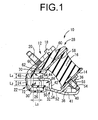
- FIGS. 1 through 3 illustrate an engine mount 10 as an embodiment of the invention.
- an upper fixture 12 serving as the upper mounting plate fixture and a lower fixture 14 serving as the lower mounting plate fixture are disposed at a certain distance from each other, and are joined together by a rubber elastic body 16.
- the vertical direction as a rule refers to the up and down or vertical direction in FIG 1.
- the upper fixture 12 is in the form of a thick, generally rectangular flat plate, and is tilted at a certain angle of incline relative to the horizontal direction (left and right in FIG. 1).
- a protrusion 18 with a generally columnar shape of small diameter is provided at one end surface in the thicknesswise direction (left upward slant in FIG. 1) near one end in the widthwise direction (right upward slant in FIG. 1) of the upper fixture 12.
- a fixing bolt 20 integrally formed in a protruding manner near the other end in the widthwise direction (left downward slant in FIG. 1) at the same end surface.
- the fixing bolt 20 is provided facing inward in the direction in which the upper fixture 12 is inclined (left in FIG. 1).
- An upper stopper 22 is also integrally formed at the other end in the widthwise direction (left downward slant in FIG. 1) of the upper fixture 12.
- the upper stopper 22 has a generally L-shaped cross section, and comprises a downward facing protrusion 24 and a first contact component 26.
- the downward facing protrusion 24 is in the form of a generally rectangular flat plate extending a certain length vertically downward (downward in FIG. 1) from the bottom end edge of the upper fixture 12.
- the downward distal end of the downward facing protrusion 24 is bent inwardly to form the shape of an L, whereby the first contact component 26 is integrally formed with the distal end of the downward facing protrusion 24.
- the first contact component 26 is in the form of a generally rectangular flat plate, and extends generally horizontally to one side in the horizontal direction (right in FIG. 1). In this embodiment in particular, the first contact component 26 is located generally vertically below the fixing bolt 20 in the upper fixture 12.
- the lower fixture 14 is disposed a certain distance apart from the upper fixture 12.
- the lower fixture 14 is in the form of a generally rectangular flat plate, and,is tilted at generally the same angle of incline as the upper fixture 12 relative to the horizontal direction (left and right in FIG. 1).
- the upper fixture 12 and lower fixture 14 are thus inclined in the same direction (right slanting direction in FIG. 1), so that they face each other at a distance apart from each other in the direction orthogonal to the incline direction (left slanting direction in FIG. 1).
- the rubber elastic body 16 is disposed in the plane between the upper fixture 12 and lower fixture 14 facing each other.
- the rubber elastic body 16 is in the form of a generally rectangular block, where one end surface in the axial direction is bonded by vulcanization to the surface of the upper fixture 12 facing the lower fixture 14, and the other end surface in the axial direction is bonded by vulcanization to the surface of the lower fixture 14 facing the upper fixture 12.
- the rubber elastic body 16 is in the form of an integrally vulcanized product 28 equipped with an upper fixture 12 or lower fixture 14.
- the center axis extending in the longitudinal direction (left slanting direction in FIG.
- a cushioning rubber layer 30 is also deposited on the upper stopper 22 consisting of the downward facing protrusion 24 and the first contact component 26.
- the cushioning rubber layer 30 is integrally formed with the rubber elastic body 16, and is deposited to a uniform thickness along generally the entire upper stopper 22.
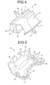
- a lower bracket 32 is attached as a separate fixture forming the lower stopper to the lower fixture 14.
- the lower bracket 32 comprises a floor wall 34 which is generally rectangular when viewed flat.
- a fixing plate 36 is also integrally formed at one end in the lateral widthwise direction (right downward slanting direction in FIG. 5) of the floor wall 34.
- the fixing plate 36 is in the form of a generally rectangular plate, and rises upward at a certain angle of inclination from the floor wall 34, both edges in the widthwise direction being integrally formed with the center in the widthwise direction of the floor wall 34 via side walls 38 and 38 which are generally triangular when viewed from the side.
- Each support 40 is in the form of generally rectangular flat plates with ribs integrally formed at the outer peripheral edges, and have a positioning hole 41, that is generally rectangular when viewed flat, in the center.
- a lower bracket 32 is attached as a separate fixture forming the lower stopper to the lower fixture 14.
- the lower bracket 32 comprises a floor wall 34 which is generally rectangular when viewed flat.
- a fixing plate 36 is also integrally formed at one end in the lateral widthwise direction (right downward slanting direction in FIG. 5) of the floor wall 34.
- the fixing plate 36 is in the form of a generally rectangular plate, and rises upward at a certain angle of inclination from view for wall 34, both edges in the widthwise direction being integrally formed with the center in the widthwise direction of the floor wall 34 via side walls 38 and 38 which are generally triangular when viewed from the side.
- the supports 40 are in the form of generally rectangular flat plates with ribs integrally formed at the outer peripheral edges, and have a positioning hole 41, that is generally rectangular when viewed flat, in the center.
- An upward facing protrusion 42 is also integrally formed at the other end in the lateral widthwise direction (left upward slanting direction in FIG. 5) of the floor wall 34.
- the upward facing protrusion 42 is in the form of a generally rectangular flat plate extending a certain length along the widthwise direction in the center in the widthwise direction (right slanting direction in FIG. 5) of the floor wall 34, and protrudes upward at a certain angle of inclination relative to the floor wall 34.
- the upward distal end of the upward facing protrusion 42 is bent to form the shape of an L, whereby a second contact component 44 is integrally formed with the distal end of the upward facing protrusion 42.
- the second contact component 44 is in the form of a generally rectangular flat plate, and extends horizontally in the direction orthogonal to the upward facing protrusion 42.
- Both ends in the widthwise direction (right slanting direction in FIG. 5) of the second contact component 44 also protrude a certain length in the outward protruding direction past the protruding end 46 provided at the distal end in the protruding direction (left slanting direction in FIG. 5) of the second contact component 44.
- Widthwise contact components 48 extending a certain length from the protruding end 46 toward the outward protruding direction are thus integrally provided on both sides in the widthwise direction of the protruding end 46.
- the center of one end in the lateral widthwise direction (left upward slant in FIG. 5) in the second contact component 44 is opened in a concave form toward the outward protruding direction by means of the protruding end 46 and the pair of widthwise contact components 48 and 48.
- integralally formed at both ends in the widthwise direction of the upward facing protrusion 42 are vertical walls 50 such that the two ends extend outward along the plane between the second contact component 44 and the floor wall 34 facing each other.
- the floor wall 34, upward facing protrusion 42, and second contact component 44 are thus connected by the pair of vertical walls 50 and 50, while the upward facing protrusion 42, second contact component 44, and pair of vertical walls 50 and 50 form a generally pocket-shaped structure overall that opens downward.
- Fixing holes 52 are also provided as bolt fixing positions on both sides in the widthwise direction of the second contact component 44 in the floor wall 34 of the lower bracket 32.
- a retainer fixture 58 is also embedded in the integrally vulcanized product 28.
- the retainer fixture 58 is in the form of a generally rectangular flat plate, and is tilted at a certain distance so as to extend generally parallel to the upper fixture 12 in the plane between the upper fixture 12 and lower fixture 14 facing each other.
- the retainer fixture 58 is also fixed by means of bonding or the like to the upper fixture 12 via a plurality of bonding tabs 60 extending in the direction in which the upper fixture 12 and retainer fixture 58 face each other.
- the retainer 58 is integrally formed by vulcanization molding with the rubber elastic body 16 along with the upper fixture 12 or lower fixture 14 so as to be embedded in the rubber elastic body 16 in the integrally vulcanized product 28.
- the end at the bottom in the direction in which the retainer fixture 58 is tilted is bent in the generally parallel extending direction (left and right in FIG. 1), and a third contact component 62 is integrally formed with the end.
- the third contact component 62 is in the form of a generally rectangular flat plate, and is formed so as to spread out in the generally horizontal direction.
- the third contact component 62 is interposed extending generally parallel to the first contact component 26 in the plane between the fixing bolt 20 in the upper fixture 12 and the first contact component 26 in the upper stopper 22 facing each other. In other words, the third contact component 62 is positioned generally vertically under the fixing position of the fixing bolt 20 in the upper fixture 12.
- a cushioning rubber 64 integrally formed with the rubber elastic body 16 is deposited in the plane where the third contact component 62 faces the first contact component 26.
- the fixing plate 36 of the lower bracket 32 is closely placed on and securely fixed to the lower fixture 14 of the integrally vulcanized molded product 28, by screwing a fixing nut 56 onto an mounting bolt 54 that is fixed to generally the middle of the lower fixture 14 and extending through the fixing plate 36.
- the engine mount 10 is thus constructed.
- the pair of fixing holes 52, 52 have also been provided on both sides in the widthwise direction of the second contact component 44 in the floor wall 34 of the lower bracket 32, allowing the lower bracket 32 to be positioned nearer to the second contact component 44 than the mounting bolt 54 fixed to the lower fixture 14.
- the downward facing protrusion 24 of the upper stopper 22 is between the pair of widthwise direction contact components 48, 48 in the lower bracket 32, and the first contact component 26 in the upper stopper 22 is located at a certain distance below the second contact component 44 of the lower bracket 32 via the cushioning rubber layer 30 deposited on the first contact component 26. That is, the first contact component 26 and second contact component 44 are positioned facing each other at a certain distance from each other in the vertical direction.
- a stopper mechanisms 66 in the rebound direction consisting of the first contact component 26, second contact component 44, and cushioning rubber layer 30 is thus provided in the engine mount 10.
- FIGS. 6 and 7 show that part of the cushioning rubber layer 30 is in contact with the second contact component 44 before the engine mount 10 is mounted on a vehicle, that is, when the static load of a power unit 68 described below is not being applied.
- the second contact component 44 of the lower bracket 32 and the third contact component 62 of the retainer fixture 58 are positioned facing each other apart from each other in the vertical direction via the cushioning rubber 64 deposited on the third .contact component 62.
- a stopper mechanism 70 in the bound direction consisting of the second contact component 44, third contact component 62, and cushioning rubber 64 is thus provided in the engine mount 10.
- the downward facing protrusion 24 in the upper stopper 22 and the protruding end 46 of the second contact component 44 are also positioned facing each other at a distance from each other in the lateral direction (left and right in FIGS. 1 and 6) of the mount orthogonal to the widthwise direction, via the cushioning rubber layer 30 deposited on the rubber elastic body 16 side of the surface of the downward protrusion 24.
- a lateral stopper mechanism 72 comprising the downward facing protrusion 24, the second contact component 44 (protruding end 46), and the cushioning rubber layer 30 is thus provided in the engine mount 10.
- Both ends in the widthwise direction of the downward facing protrusion 24 in the upper stopper 22 are also positioned apart from each other at a certain distance L1 in the widthwise direction (up and down in FIG. 7) relative to the widthwise contact components 48 in the lower bracket 32 via the cushioning rubber layer 30 deposited on the downward facing protrusion 24.
- the downward facing protrusion 24 on which the cushioning rubber layer 30 has been deposited is interposed at a certain interval 2L1 in the plane between the pair of lateral contact components 48, 48 facing each other.
- one of the plurality of elastic main axes of the rubber elastic body 16 extends in the direction in which the upper fixture 12 and lower fixture 14 face each other, that is, above the upper fixture 12 or lower fixture 14, which is the direction in which the major vibration load relative to the rubber elastic body 16 is input.
- a pair of engine mounts 10 constructed in the manner described above are mounted between the power unit 68 and a vehicle body 76.
- the power unit 68 equipped with an engine, transmission, and the like has an inertia axis extending generally in the torque roll axial direction through its center of gravity
- a pair of mounting brackets 78, 78 is fixed to the power unit 68 on both side of the inertia axis, projecting generally in the horizontal direction vertically below the' inertia axis.
- the ends of the mounting brackets 78 are slanted downward on the inside of the power unit 68.
- Mounting seat surfaces 80 extending generally horizontally at positions corresponding to the ends of the mounting brackets 78 are formed on the vehicle body 76.
- the upper fixtures 12 of the engine mounts 10 are placed on the ends of the mounting brackets 78 on the power unit 68 side to allow the protrusions 18 of the upper fixtures 12 at the engine mounts 10 to be engaged with the positioning holes formed at certain positions at the ends, and the fixing bolts 20 of the upper fixtures 12 are passed through and screwed into fixing nuts 82.
- the lower brackets 32 of the engine mounts 10 are placed on the mounting seat surfaces 80 on the body 76 side to allow the protrusions at the certain positions to be engaged at the positioning holes 41 of the lower brackets 32, and fixing bolts 84 are inserted through the fixing holes 52 of the lower brackets 32 and screwed into fixing nuts 86.
- the pair of engine mounts 10, 10 are thus disposed on both sides of the torque roll axis of the power unit 68, and are mounted between the power unit 68 and vehicle body 76, with the elastic main axis of the rubber elastic body 16, which extends in the direction in which the upper fixture 12 and lower fixture 14 face each other, being tilted upward on the inside of the power unit 68.
- the support load of the power unit 68 is exerted on the engine mounts 10, so that the rubber elastic body 16 in the state illustrated in FIG. 1 is the elastically deformed from the state illustrated in FIG. 6. That is, in the absence of a vibration load, the second contact component 44 and the first contact component 26 coated with the cushioning rubber layer 30 in the stopper mechanism 66 in the rebound direction are positioned facing each other at a certain distance L2 apart from each other in the vertical direction (up and down in FIGS. and 1 and 8) of the vehicle.
- the second contact component 44 and the third contact component 62 coated with the cushioning rubber 64 in the stopper mechanism 70 in the bound direction are positioned facing each other at a certain distance L4 apart from each other in the vertical direction of the vehicle.
- the protruding end 46 of the second contact component 44 and the downward facing protrusion 24 coated with the cushioning rubber layer 30 in the stopper mechanism 72 in the lateral direction are positioned facing each other at a certain distance L3 apart from each other in the lateral direction (left and right in FIGS. 1 and 8) of the vehicle.
- the lateral contact components 48 of the second contact component 44 and one each of the two widthwise ends of the downward facing protrusion 24 coated with the cushioning rubber layer 30 in the stopper mechanism 74 in the widthwise direction are positioned facing each other at a certain distance L1 apart from each other in the forward and backward direction (up and down in FIG. 7) of the vehicle.
- the rebound, bound, lateral, and widthwise stopper mechanisms 66, 70, 72, and 74 are all positioned vertically below the mounting position of the fixing bolts 20 as the bolt fixing positions relative to the power unit 68.
- the fixing bolts 20 are also located in a position deviating more toward the inside of the power unit than the elastic main axis of the rubber elastic body 16 on the upper fixture 12, so that the upper stopper 22 is bolted to the power unit 68 at a location deviating more toward the inside of the power unit 68 than the location of the elastic main axis.
- the pair of fixing holes 52, 52 in the lower brackets 32 are positioned nearer the second contact component 44 than the mounting bolt 54 for fixing the lower fixture 14 and lower brackets 32, so that the lower brackets 32 are bolted to the vehicle body 76 at a position deviating more toward the inside of the power unit 68 than the elastic main axis of the rubber elastic body 16 in the lower fixture 14.
- the engine mount 10 with this type of structure is thus equipped with rebound, bound, lateral, and widthwise stopper mechanisms 66, 70, 72, and 74, so that when a certain vibration load in each direction is input between the power unit 68 and the vehicle body 76, that is, between the upper fixture 12 and the lower fixture 14 (lower bracket 32), the pairs of contact components in the stopper mechanisms corresponding to the directions in which the vibration is input come into contact with each other, thereby controlling the relative displacement between the upper fixture 12 and lower fixture 14 in the direction in which the vibration is input.
- the pairs of contact components in the various stopper mechanisms come into contact with each other, the impact on the pairs of contact components is absorbed based on the elastic displacement of the cushioning rubber 64 or cushioning rubber layer 30 between the contact components.
- the stopper mechanism 66 in the rebound direction or the stopper mechanism 70 in the bound direction is positioned generally vertically below the mounting position of the fixing bolt 20 by which the upper stopper 22 is fixed to the power unit 68.
- the fixing bolt 20 is positioned on the line of action of the force of contact in the rebound direction (up and down in FIG. 1) between the second contact component 44 and the first contact component 26 in the rebound stopper mechanism 66 and on the line of action of the force of contact in the bound direction (up and down in FIG. 1) between the third contact component 62 and the second contact component 44 in the bound stopper mechanism 70.
- the areas where the power unit 68 and mounts 10 are fixed are located on the line of action of the force of contact in the direction in which vibration is input between the two contact components of the rebound stopper mechanism 66 and the bound stopper mechanisms 70, to efficiently eliminate problems in preserving the rigidity of the fixing areas which can occur as a result of the moment produced in each direction at the fixing areas due to the plurality of stopper mechanisms corresponding to each direction in which vibration is input. It is thus possible to ensure better withstand load.
- the rebound, bound, lateral, and widthwise stopper mechanisms 66, 70, 72, and 74 are also positioned concentrating on locations deviating further toward the inside of the power unit 68 than the elastic main axis of the rubber elastic body 16 of the lower fixture 14, so that the overall shape is more compact, resulting in more efficient use of space on the vehicle body.
- the lower brackets 32 are bolted to the mounting seating surfaces 80 of the vehicle body 76 at a position deviating more toward the inside of the power unit 68 than the position of the elastic main axis of the rubber elastic body 16 on the lower fixture 14, so that the contact force of the pairs of contact components in the rebound, bound, lateral, and widthwise stopper mechanisms 66, 70, 72, and 74 is efficiently transmitted to the fixing areas, with more effectively suppressed moment around the fixing areas when the pairs of contact components come into contact with each other.
- the upper fixture 12 and lower fixture 14 (lower bracket 32) are fixed relative to the power unit 68 and vehicle body 76 at positions near the stopper mechanisms, resulting in greater support rigidity.
- the natural frequency of the upper fixture 12 and lower fixture 14 can thus be set to a sufficiently high frequency spectrum, to attenuate or avoid any worsening vibration as a result of resonance and thus achieve better vibration-proof effects.
- a cushioning rubber layer 30 is formed along the entire first contact component 26 in the upper stopper 22.
- the resulting uniform cushioning rubber on the rebound, lateral, and widthwise stopper mechanisms 66, 72, and 74 is thus easier to manufacture.
- the lower fixture and lower bracket were separately formed in the above embodiment, but the may be integrally formed so that the lower stopper is integrally provided on the lower fixture.
- the lower bracket is also not limited to the one shown in the embodiment. Specifically, a lower bracket 88 can be used, wherein as illustrated in FIG. 9, for example, the fixing holes 52 are provided in the floor wall 34 on both sides in the lateral direction of the second contact component 44, and are disposed on generally the same line 10-10 in the widthwise direction as the second contact component 44. Parts and areas of the lower bracket 88 in this specific example having substantially the same structure as the above embodiment are indicated by the same numerals in FIG. 9 and redundant explanations for those parts will be omitted.
- the upper stopper may also be formed separately from the upper fixture, and may be placed closely on the external surface of the upper fixture and fixed with a bolt or the like.
- a pair of engine mounts are disposed on the automobile on both sides of the torque roll axis of the power unit, but of course one or a plurality of mounts can be set up in appropriate locations.
- the present invention is applied to a specific example of a solid type of engine mount in the invention in which the power unit and the vehicle body are elastically joined by a rubber elastic body installed between the power unit and vehicle body, but the invention is not limited to the illustrated embodiment.
- the present invention is similarly applicable to fluid-filled type engine mounts and various other types of engine mounts, as well.
Abstract
Description
- The disclosure of Japanese Patent Application No. 2004-036202 filed on February 13, 2004 including the specification, drawings and abstract is incorporated herein by reference in its entirety.
- The present invention relates to an engine mount that is installed between a power unit and vehicle body to provide vibration isolating support of the power unit against the vehicle body, and more particular to an engine mount with a novel structure comprising a stopper mechanism to limit an amount of relative displacement of the power unit against the vehicle body in a cushion-wise fashion.
- A plurality of engine mounts have conventionally been installed between automobile vehicle bodies and their power units to allow the power units to be supported in a vibration-damping fashion relative to the vehicle bodies. Such engine mounts are generally composed of an upper mounting fixture and a lower mounting fixture which are disposed apart from each other and joined by a rubber elastic body. As disclosed in JP-A-7-89356, for example, they are set up at the bottom on either side of the torque roll axis of the power unit to support the power unit from below on both sides in the lateral direction.
- The spring properties of the engine mounts should be relaxed enough to achieve good vibration damping when such engine mounts are used for the vibration-damping support mechanisms for power units in relation to vehicle bodies. However, it is necessary to control significant displacement of the power unit relative to the vehicle body in instances of substantial vibration load. A stopper mechanism for cushioning relative displacement has thus often been provided on the upper and lower mounting fixtures attached to either the vehicle body or power unit in conventional engine mounts.
- Such stopper mechanisms are generally constructed by forming contact protrusions that protrude outward from the upper and lower mounting fixtures toward each other, with the contact protrusions disposed apart at a certain interval in the vibration input direction on either side of cushioning rubber.
- However, the pair of engine mounts mounted so as to support the power unit at an incline from below on either side of the axis as described above have suffered from the following avoidable problem. Namely, because of the required power unit support properties, as noted in the aforesaid JP-A-7-89356, the mount center axis, which is the elastic main axis extending in the direction in which the upper and lower mounting fixtures face each other, is tilted upward on the inside of the power unit. Therefore, the point of contact at the contact protrusions forming the stopper mechanism is considerably outside the horizontal direction from the upper or lower mounting fixtures.
- That is, when the stopper mechanism is formed by the protruding formation of the contact protrusions slanting inwardly from the upper and lower mounting fixtures as indicated in FIGS. 5 and 6 of JP-A-7-89356, the result is a greater distance in the horizontal direction from the point where the lower mounting fixture is fixed to the vehicle body to the point of contact of the contact protrusions. When vertical stopper load is exerted on the contact protrusions, substantial moment acts on the point where the lower mounting fixture is fixed to the vehicle body, making it difficult to obtain satisfactory strength or withstand load capability. When, on the other hand, the stopper is formed by the protruding formation of contact protrusions slanting outwardly from the upper and lower mounting fixtures as indicated in FIGS. 1 and 2 in JP-A-7-89356, the result is a greater distance in the horizontal direction from the point where the upper mounting fixture is fixed to the power unit to the point of contact of the contact protrusions. When vertical stopper load is exerted on the contact protrusions, substantial moment acts on the point where the upper mounting fixture is fixed to the power unit, making it difficult to obtain satisfactory strength or withstand load capability.
- In the stopper mechanism for the power unit shown in either FIGS. 1 and 2 or 5 and 6 in JP-A-7-89356, the contact protrusion of the upper mounting fixture that is fixed to the power unit is in the shape of a large pocket which not only is wrapped around so that the contact protrusion on the lower mounting fixture is encompassed outwardly from below, but the walls are integrally formed on both the left and right sides. The resulting increase in the mass of the upper mounting fixture results in a lower natural frequency, with the risk of worsening vibration as a result of resonance in the upper mounting fixture in the low frequency range which tends to cause problems in preventing vehicle vibration.
- It is therefore one object of this invention to provide an engine mount of novel structure capable of providing a stopper mechanism for limiting an amount of relative displacement of the power unit against the vehicle body, while assuring its high withstand load capability with efficiency.
- The above and/or optional objects of this invention may be attained according to at least one of the following modes of the invention. Each of these modes of the invention is numbered like the appended claims and depending from the other mode or modes, where appropriate, to indicate possible combinations of elements or technical features of the invention. It is to be understood that the principle of the invention is not limited to these modes of the invention and combinations of the technical features, but may otherwise be recognized based on the teachings of the present invention disclosed in the entire specification and drawings or that may be recognized by those skilled in the art in the light of the present disclosure in its entirety.
- A first mode of the present invention provides an engine mount comprising: An engine mount comprising: (a) an upper mounting plate fixture fixable to a power unit; (b) a lower mounting plate fixture disposed facing to the upper mounting plate fixture at a distance from each other, and fixable to a vehicle body; (c) a rubber elastic body disposed between and elastically connecting the upper and lower mounting plate fixtures, (d) the engine mount adapted to be disposed on either side of a torque roll axis of the power unit with the upper and lower mounting plate fixtures respectively fixed to the power unit and vehicle body so that an elastic main axis of the rubber elastic body is disposed at an incline slanting upward toward an inside of the power unit; (e) an upper stopper formed by being integrally formed with the upper mounting plate fixture or by fixing a separate fixture to the upper mounting plate fixture such that a downward facing protrusion is provided protruding downward on a side of the power unit from the upper mounting plate fixture, and a distal end of the downward facing protrusion is bent into an L-shape, so as to provide a first contact component extending generally horizontally toward the rubber elastic body; (f) a lower stopper formed by being integrally formed with the lower mounting plate fixture or by fixing a separate fixture to the lower mounting plate fixture such that an upward facing protrusion is provided protruding upward on the side of the power unit from the lower mounting plate fixture, and a distal end of the upward facing protrusion is bent into an L-shape, so as to provide a second contact component extending generally horizontally toward a side opposite the rubber elastic body, whereby the first contact component is thrust into the bottom of the second contact component so that the first and second contact components are positioned facing each other at a distance from each other generally in a vertical direction; and (g) a cushioning rubber formed on at least one of the first and second contact components to form a stopper mechanism in a rebound direction, wherein the upper stopper is bolted to the power unit at a position deviating more toward the inside of the power unit than a position of the elastic main axis of the rubber elastic body on the upper mounting plate fixture so that the stopper mechanism in the rebound direction is positioned generally vertically below the position where the upper stopper is bolted to the power unit, and wherein the lower stopper is bolted to the vehicle body at a position deviating more toward the inside of the power unit than the position of the elastic main axis of the rubber elastic body on the lower mounting plate fixture.
- In engine mounts constructed according to this mode, the stopper mechanism in the rebound direction is positioned generally vertically below the position where the upper stopper is bolted to the power unit. When the stopper mechanism in the rebound direction is activated, the position where the upper stopper is bolted to the power unit is located on the line of action of the force of contact in the rebound direction between the first and second contact components. With this arrangement, the moment produced relative to the bolt fixing position of the upper stopper as a result of the contact force in the rebound direction is thus effectively suppressed, ensuring better withstand load capability in the bolt fixing position and the stopper mechanism.
- In this mode, moreover, the lower stopper is bolted to the vehicle body at a position deviating more toward the inside of the power unit than the position of the elastic main axis of the rubber elastic body on the lower mounting plate fixture. With this arrangement, the contact force between the first and second contact components when the stopper mechanism is activated is efficiently transmitted from the lower stopper to the vehicle body, with more attenuated moment acting on the areas where the lower stopper is fixed to the vehicle body, as well as greater support strength of the lower stopper by the vehicle body and more advantageous withstand load capability in the lower stopper. Meant by the elastic main axis in this mode is the elastic main axis of the mount extending generally facing the upper and lower mounting plate fixtures.
- The engine mount of this mode therefore ensures better withstand load capability at the positions where the lower stopper is fixed to the vehicle body as well as in the positions where the upper stopper is bolted to the power unit, allowing a greater withstand load capability to be effectively achieved in the stopper mechanisms.
- In this mode, the upper stopper and lower stopper are fixed to the power unit and vehicle body, respectively at positions near the first and second contact components, resulting in greater support rigidity in the upper and lower stoppers. This makes it possible to set the natural frequency of the upper and lower stoppers or the upper and lower mounting plate fixtures to a sufficiently high frequency band, to thereby attenuate or avoid any worsening vibration as a result of resonance and thus achieve better vibration damping performance.
- A second mode of the invention provides an engine mount according to the aforesaid first mode, wherein the upward facing protrusion in the lower stopper is bent toward the inside of the power unit on both sides in a widthwise direction of the first contact component in the upper stopper, so as to integrally form vertical walls joining the upward facing protrusion in the lower stopper with both edges of the second contact component in a widthwise direction, providing a generally pocket-shaped structure opening downward formed overall by the upward facing protrusion, second contact component, and the vertical walls on the both sides.
- In this mode, the lower stopper is generally in the form of a pocket or pouch comprising the second contact component and the upward facing protrusion, allowing the rigidity of the lower stopper to be improved and, as a result, the withstand load capability of the stopper mechanism to be even more advantageously improved. In this mode in particular, the pocket structure is formed by the lower stopper fixed to the vehicle body, which is subject to vibration, not the upper stopper fixed direction to the power unit, which is the source of the vibration. It is thus possible to suppress worsening vibration caused by a decrease in the natural frequency with increased weight.
- A third mode of the invention is an engine mount according to the aforesaid first or second mode, wherein the second contact component in the lower stopper is located in a position apart from and facing a surface of the downward facing protrusion of the upper stopper on a side of the rubber elastic body, at a protruding end surface thereof, and a cushioning rubber is formed on at least one of the surfaces facing each other, forming a lateral stopper mechanism; and the second contact component in the lower stopper protrudes toward the side opposite the rubber elastic body on both sides in the later direction of the downward facing protrusion in the upper stopper, integrally forming a pair of contact components in the widthwise direction located apart from and facing outward in the widthwise direction relative to both end surfaces in the widthwise direction of the downward facing protrusion in the upper stopper, a cushioning rubber being formed on at least one of the facing surfaces so as to form a stopper mechanism in the widthwise direction.
- In this mode, the protruding distal end component (surface) of the second contact component and a component (surface) of the downward facing protrusion on the rubber elastic body side are used to provide a stopper mechanism in the lateral direction, making it possible to produce a stopper mechanism, without increasing special parts, in which the relative displacement of the power unit in the axis-perpendicular direction to the vehicle body is limited in a cushion-wise fashion, in the horizontal direction orthogonal to the power unit torque roll axis by means of the left and right pair of engine mounts.
- The stopper mechanism in the widthwise direction formed in this mode also comprises widthwise contact components integrally formed with the second contact component and both ends in the widthwise direction of the downward facing component, making it possible to produce a stopper mechanism, without increasing special parts, in which the relative displacement of the power unit in the axial direction relative to the vehicle body, is limited in a cushion-wise fashion in the horizontal direction generally along the torque roll axis of the power unit.
- That is, in this mode, the lateral stopper mechanism and widthwise stopper mechanism can involve the combined use of the second contact component and downward facing protrusion, in addition to which the rebound stopper mechanism in the first mode of the invention comprises the second contact component and downward facing protrusion equipped with the first contact component. With this arrangement, stopper mechanisms corresponding to each vibrating direction can be obtained with a simpler and more compact structure.
- A fourth mode of the invention is an engine mount according to any one of the aforesaid first through third modes, wherein a third contact component is formed in the upper mounting plate fixture at a distance facing, from above, the second contact component in the lower stopper, and a cushioning rubber is formed on at least one facing surface of the second contact component or third contact component, forming a stopper mechanism in a bound direction.
- In this mode, a stopper mechanism that cushions the relative displacement of the power unit in the bound direction of the power unit relative to the vehicle body comprises the second contact component that is also used in the rebound stopper mechanism, resulting in easier manufacture with fewer components.
- In addition, the stopper mechanism in the bound direction, which comprises the second contact component and the third contact component positioned apart from and facing, from above, the second contact component, is positioned facing in generally the direction vertical to the bound stopper mechanism on both sides of the second contact component so that it is vertically below the position where the upper stopper is bolted to the power unit. Moment around the bolt fixing position is thus suppressed in the same manner as with the rebound stopper mechanism when the second and third contact components come into contact with each other, affording better withstand load capability.
- In this mode, the bound direction refers to the downward vertical direction, which is where the weight of the power unit acts on the vehicle body. The third contact component may be integrally formed by curving or bending the upper mounting plate fixture, for example, but may also be formed by securing a separate fixture to the upper mounting plate fixture by welding or the like.
- The cushioning rubber used in the above stopper mechanisms in the rebound, lateral, or widthwise directions or the like in the engine mount in this mode is integrally deposited on the downward facing protrusion comprising the first contact component in the upper stopper. This makes manufacturing easier.
- A fourth mode of the invention is an engine mount according to any one of the aforesaid first through fourth modes, wherein the upper mounting plate fixture is extended toward the inside of the power unit so that the upper stopper is integrally formed with the upper mounting plate fixture; the bolt fixing the upper mounting plate fixture to the power unit is set up deviating more toward the inside of the power unit than the elastic main axis of the rubber elastic body, whereas the lower stopper is formed by bolting a separate fixture to the lower mounting plate fixture; and the lower stopper is bolted to the vehicle body at a location nearer the second contact component than the position where the lower mounting plate fixture is bolted in the lower stopper.
- In this mode, the positions where the upper stopper is bolted to the power unit and the lower stopper is bolted to the vehicle body can be even closer to the rebound stopper mechanism. This will more effectively suppress moment produced where the upper and lower stoppers are bolted, affording even better withstand load in the upper and lower stoppers.
- A sixth mode of the invention is an engine mount according to any one of the aforesaid first through fifth modes, wherein the lower stopper is bolted at a plurality portions to the vehicle body and the plurality of portions are on both sides of the second contact component in the widthwise direction.
- In this mode, greater bolting strength to the vehicle body is achieved at the second contact component formed on the lower stopper, affording even better rigidity and withstand load capability in the lower stopper.
- In the sixth mode, the shape, size, number, or the like of the position where the lower stopper is bolted to the vehicle body are not limited. One or more bolting positions may be provided on both sides of the second contact component.
- A seventh mode of the invention is an engine mount according to the aforesaid sixth mode, wherein the positions where the lower stopper is bolted to the vehicle body are disposed on generally a same line in the widthwise direction of the second contact component.
- In this mode, the position where the lower stopper is bolted to the vehicle body is suitably closer to the rebound stopper mechanism. When load is exerted in the rebound direction, for example, the load input at the bolt positions is efficiently distributed, resulting in even better withstand load.
- In this mode, at least two bolt fixing positions, for example, may be provided on either side of the second contact component on a line extending in the widthwise direction of the second contact component, that is, may be disposed on generally the same line in the widthwise direction as the second contact component, or a suitable number of bolting positions may be provided on both sides in the widthwise direction of the second contact component on generally the same line in the widthwise direction as the second contact component. A plurality of lines extending in the widthwise direction of the second contact component can also be provided separately at right angles to the widthwise direction, so that a suitable number of bolt fixing positions are disposed on a plurality of lines.
- As will be evident from the preceding description, the engine mount of construction according to the present invention is able to provide stopper mechanisms limiting relative displacement between the upper and lower stoppers in the rebound direction wherein the action of moment at the positions where the power unit and vehicle body are fixed can be effectively suppressed, thereby ensuring better withstand load capability.
- The forgoing and/or other objects features and advantages of the invention will become more apparent from the following description of a preferred embodiment with reference to the accompanying drawings in which like reference numerals designate like elements and wherein:
- FIG. 1 is an elevational view in vertical cross section of an engine mount according to a first embodiment of the present invention, which is mounted on an automotive vehicle;
- FIG. 2 is a perspective schematic view of the engine mount of FIG. 1 as seen from a diagonally upper portion;
- FIG. 3 is a perspective schematic view of the engine mount of FIG. 1 as seen from a diagonally lower portion;
- FIG. 4 is a perspective schematic view of an integrally vulcanized product of the engine mount of FIG. 1 as seen from a diagonally upper portion;
- FIG. 5 is a perspective schematic view of a lower bracket of the engine mount of FIG. 1 as seen from a diagonally upper portion;
- FIG. 6 is an elevational view in vertical cross section of the engine mount of FIG. 1 in a state prior to being mounted on the vehicle, taken along line 6-6 of FIG. 7;
- FIG. 7 is a top plane view of the engine mount of FIG. 6;
- FIG. 8 is a schematic view showing a pair of engine mount of FIG. 1 installed on the vehicle; and
- FIG. 9 is a top plane view of an example of a lower bracket used in the engine mount of FIG. 1.
-
- Embodiments of the invention will be described in order to provide a further understanding of the invention. FIGS. 1 through 3 illustrate an
engine mount 10 as an embodiment of the invention. In the structure of theengine mount 10, anupper fixture 12 serving as the upper mounting plate fixture and alower fixture 14 serving as the lower mounting plate fixture are disposed at a certain distance from each other, and are joined together by a rubberelastic body 16. In the following description, the vertical direction as a rule refers to the up and down or vertical direction in FIG 1. - More specifically, the
upper fixture 12 is in the form of a thick, generally rectangular flat plate, and is tilted at a certain angle of incline relative to the horizontal direction (left and right in FIG. 1). Aprotrusion 18 with a generally columnar shape of small diameter is provided at one end surface in the thicknesswise direction (left upward slant in FIG. 1) near one end in the widthwise direction (right upward slant in FIG. 1) of theupper fixture 12. In addition, a fixingbolt 20 integrally formed in a protruding manner near the other end in the widthwise direction (left downward slant in FIG. 1) at the same end surface. In other words, the fixingbolt 20 is provided facing inward in the direction in which theupper fixture 12 is inclined (left in FIG. 1). - An
upper stopper 22 is also integrally formed at the other end in the widthwise direction (left downward slant in FIG. 1) of theupper fixture 12. Theupper stopper 22 has a generally L-shaped cross section, and comprises a downward facingprotrusion 24 and afirst contact component 26. The downward facingprotrusion 24 is in the form of a generally rectangular flat plate extending a certain length vertically downward (downward in FIG. 1) from the bottom end edge of theupper fixture 12. The downward distal end of the downward facingprotrusion 24 is bent inwardly to form the shape of an L, whereby thefirst contact component 26 is integrally formed with the distal end of the downward facingprotrusion 24. Thefirst contact component 26 is in the form of a generally rectangular flat plate, and extends generally horizontally to one side in the horizontal direction (right in FIG. 1). In this embodiment in particular, thefirst contact component 26 is located generally vertically below the fixingbolt 20 in theupper fixture 12. - The
lower fixture 14 is disposed a certain distance apart from theupper fixture 12. Thelower fixture 14 is in the form of a generally rectangular flat plate, and,is tilted at generally the same angle of incline as theupper fixture 12 relative to the horizontal direction (left and right in FIG. 1). Theupper fixture 12 andlower fixture 14 are thus inclined in the same direction (right slanting direction in FIG. 1), so that they face each other at a distance apart from each other in the direction orthogonal to the incline direction (left slanting direction in FIG. 1). - The rubber
elastic body 16 is disposed in the plane between theupper fixture 12 andlower fixture 14 facing each other. The rubberelastic body 16 is in the form of a generally rectangular block, where one end surface in the axial direction is bonded by vulcanization to the surface of theupper fixture 12 facing thelower fixture 14, and the other end surface in the axial direction is bonded by vulcanization to the surface of thelower fixture 14 facing theupper fixture 12. Thus, as illustrated in FIG. 4, the rubberelastic body 16 is in the form of an integrally vulcanizedproduct 28 equipped with anupper fixture 12 orlower fixture 14. In this embodiment in particular, the center axis extending in the longitudinal direction (left slanting direction in FIG. 1) of the rubberelastic body 16 extends generally parallel to the direction in which the twofixtures elastic body 16 is disposed at a certain angle of incline from thelower fixture 14 toward theupper fixture 12. It will thus be evident that thefirst contact component 26 integrally formed with the L-shaped distal end of the downward facingcomponent 24 extends generally parallel toward the rubberelastic body 16. - A
cushioning rubber layer 30 is also deposited on theupper stopper 22 consisting of the downward facingprotrusion 24 and thefirst contact component 26. Thecushioning rubber layer 30 is integrally formed with the rubberelastic body 16, and is deposited to a uniform thickness along generally the entireupper stopper 22. - A
lower bracket 32 is attached as a separate fixture forming the lower stopper to thelower fixture 14. As illustrated in FIG. 5, thelower bracket 32 comprises afloor wall 34 which is generally rectangular when viewed flat. A fixingplate 36 is also integrally formed at one end in the lateral widthwise direction (right downward slanting direction in FIG. 5) of thefloor wall 34. The fixingplate 36 is in the form of a generally rectangular plate, and rises upward at a certain angle of inclination from thefloor wall 34, both edges in the widthwise direction being integrally formed with the center in the widthwise direction of thefloor wall 34 viaside walls plate 36 in thefloor wall 34, there are formed a pair ofsupports side walls 38. Eachsupport 40 is in the form of generally rectangular flat plates with ribs integrally formed at the outer peripheral edges, and have apositioning hole 41, that is generally rectangular when viewed flat, in the center. - A
lower bracket 32 is attached as a separate fixture forming the lower stopper to thelower fixture 14. As illustrated in FIG. 5, thelower bracket 32 comprises afloor wall 34 which is generally rectangular when viewed flat. A fixingplate 36 is also integrally formed at one end in the lateral widthwise direction (right downward slanting direction in FIG. 5) of thefloor wall 34. The fixingplate 36 is in the form of a generally rectangular plate, and rises upward at a certain angle of inclination from view forwall 34, both edges in the widthwise direction being integrally formed with the center in the widthwise direction of thefloor wall 34 viaside walls plate 36 in thefloor wall 34 are formed a pair ofsupports side walls 38. The supports 40 are in the form of generally rectangular flat plates with ribs integrally formed at the outer peripheral edges, and have apositioning hole 41, that is generally rectangular when viewed flat, in the center. - An upward facing
protrusion 42 is also integrally formed at the other end in the lateral widthwise direction (left upward slanting direction in FIG. 5) of thefloor wall 34. The upward facingprotrusion 42 is in the form of a generally rectangular flat plate extending a certain length along the widthwise direction in the center in the widthwise direction (right slanting direction in FIG. 5) of thefloor wall 34, and protrudes upward at a certain angle of inclination relative to thefloor wall 34. The upward distal end of the upward facingprotrusion 42 is bent to form the shape of an L, whereby asecond contact component 44 is integrally formed with the distal end of the upward facingprotrusion 42. Thesecond contact component 44 is in the form of a generally rectangular flat plate, and extends horizontally in the direction orthogonal to the upward facingprotrusion 42. - Both ends in the widthwise direction (right slanting direction in FIG. 5) of the
second contact component 44 also protrude a certain length in the outward protruding direction past the protrudingend 46 provided at the distal end in the protruding direction (left slanting direction in FIG. 5) of thesecond contact component 44.Widthwise contact components 48 extending a certain length from the protrudingend 46 toward the outward protruding direction are thus integrally provided on both sides in the widthwise direction of theprotruding end 46. In other words, the center of one end in the lateral widthwise direction (left upward slant in FIG. 5) in thesecond contact component 44 is opened in a concave form toward the outward protruding direction by means of theprotruding end 46 and the pair ofwidthwise contact components - Integrally formed at both ends in the widthwise direction of the upward facing
protrusion 42 arevertical walls 50 such that the two ends extend outward along the plane between thesecond contact component 44 and thefloor wall 34 facing each other. Thefloor wall 34, upward facingprotrusion 42, andsecond contact component 44 are thus connected by the pair ofvertical walls protrusion 42,second contact component 44, and pair ofvertical walls - Fixing
holes 52 are also provided as bolt fixing positions on both sides in the widthwise direction of thesecond contact component 44 in thefloor wall 34 of thelower bracket 32. - A
retainer fixture 58 is also embedded in the integrally vulcanizedproduct 28. Theretainer fixture 58 is in the form of a generally rectangular flat plate, and is tilted at a certain distance so as to extend generally parallel to theupper fixture 12 in the plane between theupper fixture 12 andlower fixture 14 facing each other. Theretainer fixture 58 is also fixed by means of bonding or the like to theupper fixture 12 via a plurality ofbonding tabs 60 extending in the direction in which theupper fixture 12 andretainer fixture 58 face each other. Theretainer 58 is integrally formed by vulcanization molding with the rubberelastic body 16 along with theupper fixture 12 orlower fixture 14 so as to be embedded in the rubberelastic body 16 in the integrally vulcanizedproduct 28. - In this embodiment, the end at the bottom in the direction in which the
retainer fixture 58 is tilted (left downward slant in FIG. 1) is bent in the generally parallel extending direction (left and right in FIG. 1), and athird contact component 62 is integrally formed with the end. Thethird contact component 62 is in the form of a generally rectangular flat plate, and is formed so as to spread out in the generally horizontal direction. Thethird contact component 62 is interposed extending generally parallel to thefirst contact component 26 in the plane between the fixingbolt 20 in theupper fixture 12 and thefirst contact component 26 in theupper stopper 22 facing each other. In other words, thethird contact component 62 is positioned generally vertically under the fixing position of the fixingbolt 20 in theupper fixture 12. A cushioningrubber 64 integrally formed with the rubberelastic body 16 is deposited in the plane where thethird contact component 62 faces thefirst contact component 26. - The fixing
plate 36 of thelower bracket 32 is closely placed on and securely fixed to thelower fixture 14 of the integrally vulcanized moldedproduct 28, by screwing a fixingnut 56 onto an mountingbolt 54 that is fixed to generally the middle of thelower fixture 14 and extending through the fixingplate 36. Theengine mount 10 is thus constructed. The pair of fixingholes second contact component 44 in thefloor wall 34 of thelower bracket 32, allowing thelower bracket 32 to be positioned nearer to thesecond contact component 44 than the mountingbolt 54 fixed to thelower fixture 14. - In this
engine mount 10 in particular, the downward facingprotrusion 24 of theupper stopper 22 is between the pair of widthwisedirection contact components lower bracket 32, and thefirst contact component 26 in theupper stopper 22 is located at a certain distance below thesecond contact component 44 of thelower bracket 32 via thecushioning rubber layer 30 deposited on thefirst contact component 26. That is, thefirst contact component 26 andsecond contact component 44 are positioned facing each other at a certain distance from each other in the vertical direction. Thus, astopper mechanisms 66 in the rebound direction consisting of thefirst contact component 26,second contact component 44, andcushioning rubber layer 30 is thus provided in theengine mount 10. FIGS. 6 and 7 show that part of thecushioning rubber layer 30 is in contact with thesecond contact component 44 before theengine mount 10 is mounted on a vehicle, that is, when the static load of apower unit 68 described below is not being applied. - The
second contact component 44 of thelower bracket 32 and thethird contact component 62 of theretainer fixture 58 are positioned facing each other apart from each other in the vertical direction via thecushioning rubber 64 deposited on the third .contact component 62. Thus, astopper mechanism 70 in the bound direction consisting of thesecond contact component 44,third contact component 62, and cushioningrubber 64 is thus provided in theengine mount 10. - The downward facing
protrusion 24 in theupper stopper 22 and theprotruding end 46 of thesecond contact component 44 are also positioned facing each other at a distance from each other in the lateral direction (left and right in FIGS. 1 and 6) of the mount orthogonal to the widthwise direction, via thecushioning rubber layer 30 deposited on the rubberelastic body 16 side of the surface of thedownward protrusion 24. Thus, alateral stopper mechanism 72 comprising the downward facingprotrusion 24, the second contact component 44 (protruding end 46), and thecushioning rubber layer 30 is thus provided in theengine mount 10. - Both ends in the widthwise direction of the downward facing
protrusion 24 in theupper stopper 22 are also positioned apart from each other at a certain distance L1 in the widthwise direction (up and down in FIG. 7) relative to thewidthwise contact components 48 in thelower bracket 32 via thecushioning rubber layer 30 deposited on the downward facingprotrusion 24. In other words, the downward facingprotrusion 24 on which thecushioning rubber layer 30 has been deposited is interposed at a certain interval 2L1 in the plane between the pair oflateral contact components stopper mechanism 74 in the widthwise direction comprising the downward facingprotrusion 24, the pair ofwidthwise contact components cushioning rubber layer 30 is thus provided in theengine mount 10. - In the
engine mount 10 in this embodiment, one of the plurality of elastic main axes of the rubberelastic body 16 extends in the direction in which theupper fixture 12 andlower fixture 14 face each other, that is, above theupper fixture 12 orlower fixture 14, which is the direction in which the major vibration load relative to the rubberelastic body 16 is input. - As illustrated in FIG. 8, a pair of engine mounts 10 constructed in the manner described above are mounted between the
power unit 68 and avehicle body 76. Namely, while thepower unit 68 equipped with an engine, transmission, and the like has an inertia axis extending generally in the torque roll axial direction through its center of gravity, a pair of mountingbrackets power unit 68 on both side of the inertia axis, projecting generally in the horizontal direction vertically below the' inertia axis. The ends of the mountingbrackets 78 are slanted downward on the inside of thepower unit 68. Mounting seat surfaces 80 extending generally horizontally at positions corresponding to the ends of the mountingbrackets 78 are formed on thevehicle body 76. Theupper fixtures 12 of the engine mounts 10 are placed on the ends of the mountingbrackets 78 on thepower unit 68 side to allow theprotrusions 18 of theupper fixtures 12 at the engine mounts 10 to be engaged with the positioning holes formed at certain positions at the ends, and the fixingbolts 20 of theupper fixtures 12 are passed through and screwed into fixing nuts 82. Thelower brackets 32 of the engine mounts 10 are placed on the mounting seat surfaces 80 on thebody 76 side to allow the protrusions at the certain positions to be engaged at the positioning holes 41 of thelower brackets 32, and fixingbolts 84 are inserted through the fixing holes 52 of thelower brackets 32 and screwed into fixing nuts 86. The pair of engine mounts 10, 10 are thus disposed on both sides of the torque roll axis of thepower unit 68, and are mounted between thepower unit 68 andvehicle body 76, with the elastic main axis of the rubberelastic body 16, which extends in the direction in which theupper fixture 12 andlower fixture 14 face each other, being tilted upward on the inside of thepower unit 68. - With the engine mounts 10 mounted in this way, the support load of the
power unit 68 is exerted on the engine mounts 10, so that the rubberelastic body 16 in the state illustrated in FIG. 1 is the elastically deformed from the state illustrated in FIG. 6. That is, in the absence of a vibration load, thesecond contact component 44 and thefirst contact component 26 coated with thecushioning rubber layer 30 in thestopper mechanism 66 in the rebound direction are positioned facing each other at a certain distance L2 apart from each other in the vertical direction (up and down in FIGS. and 1 and 8) of the vehicle. - The
second contact component 44 and thethird contact component 62 coated with the cushioningrubber 64 in thestopper mechanism 70 in the bound direction are positioned facing each other at a certain distance L4 apart from each other in the vertical direction of the vehicle. The protrudingend 46 of thesecond contact component 44 and the downward facingprotrusion 24 coated with thecushioning rubber layer 30 in thestopper mechanism 72 in the lateral direction are positioned facing each other at a certain distance L3 apart from each other in the lateral direction (left and right in FIGS. 1 and 8) of the vehicle. Thelateral contact components 48 of thesecond contact component 44 and one each of the two widthwise ends of the downward facingprotrusion 24 coated with thecushioning rubber layer 30 in thestopper mechanism 74 in the widthwise direction are positioned facing each other at a certain distance L1 apart from each other in the forward and backward direction (up and down in FIG. 7) of the vehicle. - When mounted, the rebound, bound, lateral, and widthwise
stopper mechanisms bolts 20 as the bolt fixing positions relative to thepower unit 68. The fixingbolts 20 are also located in a position deviating more toward the inside of the power unit than the elastic main axis of the rubberelastic body 16 on theupper fixture 12, so that theupper stopper 22 is bolted to thepower unit 68 at a location deviating more toward the inside of thepower unit 68 than the location of the elastic main axis. - In this embodiment, as noted above, the pair of fixing
holes lower brackets 32 are positioned nearer thesecond contact component 44 than the mountingbolt 54 for fixing thelower fixture 14 andlower brackets 32, so that thelower brackets 32 are bolted to thevehicle body 76 at a position deviating more toward the inside of thepower unit 68 than the elastic main axis of the rubberelastic body 16 in thelower fixture 14. - The
engine mount 10 with this type of structure is thus equipped with rebound, bound, lateral, and widthwisestopper mechanisms power unit 68 and thevehicle body 76, that is, between theupper fixture 12 and the lower fixture 14 (lower bracket 32), the pairs of contact components in the stopper mechanisms corresponding to the directions in which the vibration is input come into contact with each other, thereby controlling the relative displacement between theupper fixture 12 andlower fixture 14 in the direction in which the vibration is input. When the pairs of contact components in the various stopper mechanisms come into contact with each other, the impact on the pairs of contact components is absorbed based on the elastic displacement of the cushioningrubber 64 orcushioning rubber layer 30 between the contact components. - In this embodiment, the
stopper mechanism 66 in the rebound direction or thestopper mechanism 70 in the bound direction is positioned generally vertically below the mounting position of the fixingbolt 20 by which theupper stopper 22 is fixed to thepower unit 68. Thus, the fixingbolt 20 is positioned on the line of action of the force of contact in the rebound direction (up and down in FIG. 1) between thesecond contact component 44 and thefirst contact component 26 in therebound stopper mechanism 66 and on the line of action of the force of contact in the bound direction (up and down in FIG. 1) between thethird contact component 62 and thesecond contact component 44 in the boundstopper mechanism 70. When the pairs of contact components in thestopper mechanisms upper stopper 22 relative to thepower unit 68 is effectively suppressed. - That is, in this embodiment, the areas where the
power unit 68 and mounts 10 are fixed are located on the line of action of the force of contact in the direction in which vibration is input between the two contact components of therebound stopper mechanism 66 and thebound stopper mechanisms 70, to efficiently eliminate problems in preserving the rigidity of the fixing areas which can occur as a result of the moment produced in each direction at the fixing areas due to the plurality of stopper mechanisms corresponding to each direction in which vibration is input. It is thus possible to ensure better withstand load. - The rebound, bound, lateral, and widthwise
stopper mechanisms power unit 68 than the elastic main axis of the rubberelastic body 16 of thelower fixture 14, so that the overall shape is more compact, resulting in more efficient use of space on the vehicle body. - In this embodiment, the
lower brackets 32 are bolted to the mounting seating surfaces 80 of thevehicle body 76 at a position deviating more toward the inside of thepower unit 68 than the position of the elastic main axis of the rubberelastic body 16 on thelower fixture 14, so that the contact force of the pairs of contact components in the rebound, bound, lateral, and widthwisestopper mechanisms - In this embodiment, the
upper fixture 12 and lower fixture 14 (lower bracket 32) are fixed relative to thepower unit 68 andvehicle body 76 at positions near the stopper mechanisms, resulting in greater support rigidity. The natural frequency of theupper fixture 12 andlower fixture 14 can thus be set to a sufficiently high frequency spectrum, to attenuate or avoid any worsening vibration as a result of resonance and thus achieve better vibration-proof effects. - In this embodiment, a
cushioning rubber layer 30 is formed along the entirefirst contact component 26 in theupper stopper 22. The resulting uniform cushioning rubber on the rebound, lateral, and widthwisestopper mechanisms - While the presently preferred embodiment of this invention have been described in detail, for illustrative purpose only, it is to be understood that the present invention is not limited to the details of the illustrated embodiments, but may be otherwise embodied with various other changes, modifications and improvements, which may occur to those skilled in the art, without departing from the spirit and scope of the invention defined in the following claims.
- For example, the lower fixture and lower bracket were separately formed in the above embodiment, but the may be integrally formed so that the lower stopper is integrally provided on the lower fixture.
- The lower bracket is also not limited to the one shown in the embodiment. Specifically, a
lower bracket 88 can be used, wherein as illustrated in FIG. 9, for example, the fixing holes 52 are provided in thefloor wall 34 on both sides in the lateral direction of thesecond contact component 44, and are disposed on generally the same line 10-10 in the widthwise direction as thesecond contact component 44. Parts and areas of thelower bracket 88 in this specific example having substantially the same structure as the above embodiment are indicated by the same numerals in FIG. 9 and redundant explanations for those parts will be omitted. - The upper stopper may also be formed separately from the upper fixture, and may be placed closely on the external surface of the upper fixture and fixed with a bolt or the like.
- Since integrally forming both the upper stopper with the upper fixture and the lower bracket with the lower fixture will make the vulcanization mold structure for the rubber elastic body more complicated and will make the mold more complicated to open and close, it is thus more desirable to form at least one of these sets separately.
- In the above embodiment, a pair of engine mounts are disposed on the automobile on both sides of the torque roll axis of the power unit, but of course one or a plurality of mounts can be set up in appropriate locations.
- While the present invention is applied to a specific example of a solid type of engine mount in the invention in which the power unit and the vehicle body are elastically joined by a rubber elastic body installed between the power unit and vehicle body, but the invention is not limited to the illustrated embodiment. The present invention is similarly applicable to fluid-filled type engine mounts and various other types of engine mounts, as well.
Claims (8)
- An engine mount (10) comprising:wherein the upper stopper (22) is bolted to the power unit at a position deviating more toward the inside of the power unit than a position of the elastic main axis of the rubber elastic body (16) on the upper mounting plate fixture (12) so that the stopper mechanism in the rebound direction is positioned generally vertically below the position where the upper stopper (22) is bolted to the power unit, andan upper mounting plate fixture (12) fixable to a power unit;a lower mounting plate fixture (14) disposed facing to the upper mounting plate fixture (12) at a distance from each other, and fixable to a vehicle body;a rubber elastic body (16) disposed between and elastically connecting the upper and lower mounting plate fixtures (12, 14),the engine mount (10) adapted to be disposed on either side of a torque roll axis of the power unit with the upper and lower mounting plate fixtures respectively fixed to the power unit and vehicle body so that an elastic main axis of the rubber elastic body (16) is disposed at an incline slanting upward toward an inside of the power unit;an upper stopper (22) formed by being integrally formed with the upper mounting plate fixture (12) or by fixing a separate fixture to the upper mounting plate fixture (12) such that a downward facing protrusion (24) is provided protruding downward on a side of the power unit from the upper mounting plate fixture (12), and a distal end of the downward facing protrusion (24) is bent into an L-shape, so as to provide a first contact component (26) extending generally horizontally toward the rubber elastic body;a lower stopper (32) formed by being integrally formed with the lower mounting plate fixture (14) or by fixing a separate fixture to the lower mounting plate fixture (14) such that an upward facing protrusion (42) is provided protruding upward on the side of the power unit from the lower mounting plate fixture (14), and a distal end of the upward facing protrusion is bent into an L-shape, so as to provide a second contact component (44) extending generally horizontally toward a side opposite the rubber elastic body, whereby the first contact component (26) is thrust into the bottom of the second contact component (44) so that the first and second contact components (26, 44) are positioned facing each other at a distance from each other generally in a vertical direction; anda cushioning rubber (30) formed on at least one of the first and second contact components to form a stopper mechanism (66) in a rebound direction,
wherein the lower stopper (32) is bolted to the vehicle body at a position deviating more toward the inside of the power unit than the position of the elastic main axis of the rubber elastic body (16) on the lower mounting plate fixture (14). - An engine mount (10) according to claim 1, wherein the upward facing protrusion (42) in the lower stopper (32) is bent toward the inside of the power unit on both sides in a widthwise direction of the first contact component (26) in the upper stopper (22), so as to integrally form vertical walls (50) joining the upward facing protrusion (42) in the lower stopper with both edges of the second contact component (44) in a widthwise direction, providing a generally pocket-shaped structure opening downward formed overall by the upward facing protrusion (42), second contact component (44), and the vertical walls (50) on the both sides.
- An engine mount (10) according to claim 1 or 2, wherein the second contact component (44) in the lower stopper (32) is located in a position apart from and facing a surface of the downward facing protrusion (24) of the upper stopper (22) on a side of the rubber elastic body (16), at a protruding end surface (46) thereof, and a cushioning rubber (30) is formed on at least one of the surfaces facing each other, forming a lateral stopper mechanism (72); and the second contact component (44) in the lower stopper (32) protrudes toward the side opposite the rubber elastic body (16) on both sides in the later direction of the downward facing protrusion (24) in the upper stopper (22), integrally forming a pair of contact components (48) in the widthwise direction located apart from and facing outward in the widthwise direction relative to both end surfaces in the widthwise direction of the downward facing protrusion (24) in the upper stopper (22), a cushioning rubber (30) being formed on at least one of the facing surfaces so as to form a stopper mechanism (48) in the widthwise direction.
- An engine mount (10) according to any one of claims 1-3, wherein a third contact component (62) is formed in the upper mounting plate fixture (12) at a distance facing, from above, the second contact component (44) in the lower stopper (32), and a cushioning rubber (64) is formed on at least one facing surface of the second contact component (44) or third contact component (62), forming a stopper mechanism (70) in a bound direction.
- An engine mount (10) according to claim 4, wherein the third contact component (62) is formed by utilizing a retainer fixture (58) of generally rectangular flat plate that is embedded within the rubber elastic body (16) and tilted at a certain distance so as to extend generally parallel to the upper mounting plate fixture (12) in a plane between the upper and lower mounting plate fixtures (12, 14) facing each other, the retainer fixture (58) being fixed to the upper mounting plate fixture (12).
- An engine mount (10) according to any one of claims 1-5, wherein the upper mounting plate fixture (12) is extended toward the inside of the power unit so that the upper stopper (22) is integrally formed with the upper mounting plate fixture (12); a bolt (20) fixing the upper mounting plate fixture (12) to the power unit is set up deviating more toward the inside of the power unit than the elastic main axis of the rubber elastic body (16), whereas the lower stopper (32) is formed by bolting a separate fixture (32) to the lower mounting plate fixture (14); and the lower stopper (32) is bolted to the vehicle body at a location nearer the second contact component than the position where the lower mounting plate fixture is bolted in the lower stopper.
- An engine mount (10) according to any one of claims 1-6, wherein the lower stopper (32) is bolted at a plurality portions (52) to the vehicle body and the plurality of portions (52) are on both sides of the second contact component (44) in the widthwise direction.
- An engine mount (10) according to claim 7, wherein the positions (44) where the lower stopper (32) is bolted to the vehicle body are disposed on generally a same line in the widthwise direction of the second contact component (44).
Applications Claiming Priority (2)
| Application Number | Priority Date | Filing Date | Title |
|---|---|---|---|
| JP2004036202 | 2004-02-13 | ||
| JP2004036202A JP4270502B2 (en) | 2004-02-13 | 2004-02-13 | Engine mount |
Publications (3)
| Publication Number | Publication Date |
|---|---|
| EP1564054A2 true EP1564054A2 (en) | 2005-08-17 |
| EP1564054A3 EP1564054A3 (en) | 2006-07-12 |
| EP1564054B1 EP1564054B1 (en) | 2008-03-26 |
Family
ID=34697917
Family Applications (1)
| Application Number | Title | Priority Date | Filing Date |
|---|---|---|---|
| EP05250811A Active EP1564054B1 (en) | 2004-02-13 | 2005-02-11 | Engine mount |
Country Status (5)
| Country | Link |
|---|---|
| US (1) | US7182306B2 (en) |
| EP (1) | EP1564054B1 (en) |
| JP (1) | JP4270502B2 (en) |
| CN (1) | CN100394063C (en) |
| DE (1) | DE602005005528T2 (en) |
Cited By (1)
| Publication number | Priority date | Publication date | Assignee | Title |
|---|---|---|---|---|
| CN102887055A (en) * | 2012-09-28 | 2013-01-23 | 隆鑫通用动力股份有限公司 | Suspension piece |
Families Citing this family (20)
| Publication number | Priority date | Publication date | Assignee | Title |
|---|---|---|---|---|
| JP2006046361A (en) * | 2004-07-30 | 2006-02-16 | Tokai Rubber Ind Ltd | Engine mount |
| FR2895052B1 (en) | 2005-12-21 | 2012-06-15 | Eads Astrium Sas | MODULAR DEVICE FOR MULTI-AXIS ISOLATION OF VIBRATION AND SHOCK, BASED ON ELASOMER. |
| US8800967B2 (en) * | 2009-03-23 | 2014-08-12 | Southwire Company, Llc | Integrated systems facilitating wire and cable installations |
| US20090212185A1 (en) * | 2008-02-21 | 2009-08-27 | Jon Horgas | Motor mount for a vehicle |
| JP5190001B2 (en) * | 2009-02-13 | 2013-04-24 | 東洋ゴム工業株式会社 | Vibration isolator and vehicle |
| CA2758502C (en) * | 2010-11-16 | 2018-09-25 | Magna International Inc. | Bracket - active grille and actuator |
| CN102478041B (en) * | 2010-11-23 | 2013-09-25 | 沈阳黎明航空发动机(集团)有限责任公司 | Engine fastener welded by lasers and preparation method thereof |
| US9027908B1 (en) | 2011-09-01 | 2015-05-12 | Southwire Company, Llc | Field-installable pulling eye |
| US20130175743A1 (en) * | 2012-01-10 | 2013-07-11 | Aaron T. Gibbs | Scraper blade cushion |
| CN102642500A (en) * | 2012-05-10 | 2012-08-22 | 内蒙古第一机械集团有限公司 | Integrated electrical device having shockproof function |
| CN102963242A (en) * | 2012-11-27 | 2013-03-13 | 芜湖市顺昌汽车配件有限公司 | Device for fixing automobile engine support |
| CN103104644B (en) * | 2013-02-27 | 2015-09-09 | 株洲时代新材料科技股份有限公司 | A kind of for bullet train height springrate ratio rubber shock absorber |
| CN103568809B (en) * | 2013-10-31 | 2016-06-08 | 东风商用车有限公司 | A kind of limit-type engine mounting assembly of bracket |
| DE102015122226B4 (en) * | 2015-12-18 | 2022-05-19 | Vibracoustic Se | Engine mount pendulum support device |
| KR102496490B1 (en) * | 2016-12-12 | 2023-02-03 | 현대자동차주식회사 | Engine Mount And Method for Manufacturing The Same |
| JP6939454B2 (en) * | 2017-11-15 | 2021-09-22 | トヨタ自動車株式会社 | Engine mounting structure |
| CN108757796A (en) * | 2018-06-13 | 2018-11-06 | 株洲时代新材料科技股份有限公司 | A kind of method and locomotive rubber metal pad improving locomotive rubber metal pad anti-fatigue performance |
| JP7096120B2 (en) * | 2018-09-27 | 2022-07-05 | 株式会社Subaru | Power unit mount structure |
| DE102018132558A1 (en) * | 2018-12-17 | 2020-06-18 | Bayerische Motoren Werke Aktiengesellschaft | Elastomer bearing for attaching an assembly in the vehicle |
| JP7207081B2 (en) * | 2019-03-28 | 2023-01-18 | 株式会社Soken | Anti-vibration device |
Citations (5)
| Publication number | Priority date | Publication date | Assignee | Title |
|---|---|---|---|---|
| GB1550922A (en) * | 1975-08-26 | 1979-08-22 | Daimler Benz Ag | Resilient engine-mounting arrangement |
| JPS59183142A (en) * | 1983-03-31 | 1984-10-18 | Hino Motors Ltd | Method of manufacturing engine mounting provided with knock pin |
| JP2001165242A (en) * | 1999-12-08 | 2001-06-19 | Toyo Tire & Rubber Co Ltd | Vibration isolator and its stopper fitting |
| JP2002295587A (en) * | 2001-03-30 | 2002-10-09 | Tokai Rubber Ind Ltd | Engine mount |
| JP2003056642A (en) * | 2001-08-20 | 2003-02-26 | Toyo Tire & Rubber Co Ltd | Engine mount |
Family Cites Families (49)
| Publication number | Priority date | Publication date | Assignee | Title |
|---|---|---|---|---|
| JPS53117704A (en) * | 1977-03-23 | 1978-10-14 | Boge Gmbh | Motor bearing device resilient like rubber |
| JPS597138Y2 (en) * | 1979-03-12 | 1984-03-05 | トヨタ自動車株式会社 | Support device for automobile engine body |
| JPS56143835A (en) * | 1980-04-11 | 1981-11-09 | Tokai Rubber Ind Ltd | Vibration damping support |
| IT1131678B (en) * | 1980-07-04 | 1986-06-25 | Gomma Antivibranti Applic | CUSHIONING SUPPORT FOR THE SUSPENSION OF A SWINGING BODY TO A SUPPORT STRUCTURE |
| JPS57191127A (en) * | 1981-05-18 | 1982-11-24 | Nissan Motor Co Ltd | Engine mount filled with fluid |
| JPS608540A (en) * | 1983-06-27 | 1985-01-17 | Nissan Motor Co Ltd | Vibration isolating device |
| DE3474272D1 (en) * | 1983-07-22 | 1988-11-03 | Honda Motor Co Ltd | Fluid-sealed engine mounting |
| JPS60215133A (en) * | 1984-04-11 | 1985-10-28 | Nissan Motor Co Ltd | Fluid power unit mount device |
| JPS6165932A (en) * | 1984-09-05 | 1986-04-04 | Bridgestone Corp | Anti-vibration device |
| DE3433255A1 (en) * | 1984-09-11 | 1986-03-13 | Fa. Carl Freudenberg, 6940 Weinheim | DEVICE FOR THE ELASTIC STORAGE OF A VIBRATING BODY |
| JPS6196229A (en) * | 1984-10-16 | 1986-05-14 | Nissan Motor Co Ltd | Liquid enclosing type vibro-isolating body |
| US4641808A (en) * | 1985-02-22 | 1987-02-10 | Flower Wallace C | Dynamic vibration attenuator utilizing inertial fluid |
| JPH0733857B2 (en) * | 1985-03-30 | 1995-04-12 | スズキ株式会社 | Engine mount device |
| FR2613799B1 (en) * | 1987-04-13 | 1990-12-07 | Peugeot | HYDROELASTIC SUPPORT, IN PARTICULAR FOR THE SUSPENSION OF A VEHICLE ENGINE |
| FR2628496B1 (en) * | 1988-03-08 | 1990-12-21 | Peugeot | ELASTIC CONNECTION WITH HYDRAULIC RIGIDIFICATION |
| US4987679A (en) * | 1988-05-24 | 1991-01-29 | General Motors Corporation | Vehicular powertrain mount assembly |
| US5031873A (en) * | 1988-05-24 | 1991-07-16 | General Motors Corporation | Vehicular powertrain mount assembly |
| US5242146A (en) * | 1988-11-14 | 1993-09-07 | Navistar International Transportation Corp. | Engine mount having improved vibration isolation |
| FR2650355B1 (en) * | 1989-07-28 | 1994-01-28 | Paulstra Gmbh | IMPROVEMENTS ON VIBRATION DAMPING DEVICES |
| JP2884799B2 (en) * | 1991-02-04 | 1999-04-19 | 東海ゴム工業株式会社 | Fluid-filled mounting device |
| JPH0510373A (en) * | 1991-07-08 | 1993-01-19 | Bridgestone Corp | Vibration-proof device |
| GB9222656D0 (en) * | 1992-10-28 | 1992-12-09 | Draftex Ind Ltd | A controllable support element |
| GB9305474D0 (en) * | 1993-03-17 | 1993-05-05 | Jaguar Cars | Gearbox mounting |
| US5427347A (en) * | 1993-04-08 | 1995-06-27 | Lord Corporation | Apparatus for controlling active mounts |
| US5413320A (en) * | 1993-06-17 | 1995-05-09 | Lord Corporation | Fluid mount for devices such as engines |
| JPH0789356A (en) | 1993-09-22 | 1995-04-04 | Toyo Tire & Rubber Co Ltd | Supporting structure for vibration isolating mount for vehicle |
| EP0802856A2 (en) * | 1995-01-13 | 1997-10-29 | Minnesota Mining And Manufacturing Company | Damped laminates with improved fastener force retention, a method of making, and novel tools useful in making |
| US5687948A (en) * | 1995-09-26 | 1997-11-18 | Lord Corporation | Vibration isolation system including a passive tuned vibration absorber |
| US5799923A (en) * | 1995-11-03 | 1998-09-01 | The Evolution Co., Inc. | Motor mount compensator assembly |
| US5897092A (en) * | 1996-01-24 | 1999-04-27 | Toyo Tire & Rubber Co., Ltd. | Liquid enclosing type vibration isolating mount |
| US6189874B1 (en) * | 1997-07-01 | 2001-02-20 | Lord Corporation | X-configuration engine mounting |
| US5944297A (en) * | 1997-07-01 | 1999-08-31 | Lord Corporation | Isolating mount with preloaded elastomeric components |
| US6056279A (en) * | 1998-04-30 | 2000-05-02 | General Motors Corporation | Duo-pumping hydraulic mount |
| US6045328A (en) * | 1998-09-23 | 2000-04-04 | Lord Corporation | Fluid damper including flexible damping plate |
| US6129328A (en) * | 1998-09-24 | 2000-10-10 | Cooper Tire & Rubber Company | Heat resistant engine mount |
| JP3213886B2 (en) | 1999-02-22 | 2001-10-02 | 本田技研工業株式会社 | Engine mount stopper |
| US6270051B1 (en) * | 1999-05-26 | 2001-08-07 | The Standard Products Company | Drive train mount adapter plate and pivot bracket |
| JP3727495B2 (en) | 1999-08-31 | 2005-12-14 | 東海ゴム工業株式会社 | Method of manufacturing a vibration isolator having a stopper mechanism |
| GB0021140D0 (en) * | 1999-11-30 | 2000-10-11 | Kubota Kk | Dynamic dampers, and a damping support apparatus for a vehicle body using the dynamic dampers |
| FR2803002B1 (en) * | 1999-12-22 | 2002-03-08 | Hutchinson | ACTIVE HYDRAULIC ANTI-VIBRATION SUPPORT AND ACTIVE ANTI-VIBRATION SYSTEM COMPRISING SUCH A SUPPORT |
| US6349918B1 (en) * | 1999-12-27 | 2002-02-26 | Donald D. Bunker | Motor mount insert and method of forming same |
| JP3788164B2 (en) * | 2000-02-21 | 2006-06-21 | 東海ゴム工業株式会社 | Fluid filled mount |
| US6450474B1 (en) * | 2000-03-09 | 2002-09-17 | Lord Corporation | X-configuration engine mounting with locking end plates |
| JP2001304329A (en) * | 2000-04-19 | 2001-10-31 | Tokai Rubber Ind Ltd | Fluid-filled active engine mount |
| FR2812362B1 (en) * | 2000-07-28 | 2003-02-07 | Hutchinson | HYDRAULIC ANTIVIBRATORY SUPPORT AND MANUFACTURING METHOD THEREOF |
| GB2367042A (en) * | 2000-09-26 | 2002-03-27 | New Holland Uk Ltd | Radiator mounting |
| US6422545B1 (en) * | 2001-02-09 | 2002-07-23 | Delphi Technologies, Inc. | Vacuum actuated active decoupler mount |
| US6511059B2 (en) * | 2001-05-01 | 2003-01-28 | Paulstra Crc | Antivibration device and mechanical assembly comprising such antivibration device |
| JP3804475B2 (en) * | 2001-06-25 | 2006-08-02 | 日産自動車株式会社 | Anti-vibration support device stopper structure |
-
2004
- 2004-02-13 JP JP2004036202A patent/JP4270502B2/en not_active Expired - Lifetime
-
2005
- 2005-02-07 US US11/050,735 patent/US7182306B2/en active Active
- 2005-02-11 DE DE602005005528T patent/DE602005005528T2/en active Active
- 2005-02-11 EP EP05250811A patent/EP1564054B1/en active Active
- 2005-02-16 CN CNB2005100094298A patent/CN100394063C/en not_active Expired - Fee Related
Patent Citations (5)
| Publication number | Priority date | Publication date | Assignee | Title |
|---|---|---|---|---|
| GB1550922A (en) * | 1975-08-26 | 1979-08-22 | Daimler Benz Ag | Resilient engine-mounting arrangement |
| JPS59183142A (en) * | 1983-03-31 | 1984-10-18 | Hino Motors Ltd | Method of manufacturing engine mounting provided with knock pin |
| JP2001165242A (en) * | 1999-12-08 | 2001-06-19 | Toyo Tire & Rubber Co Ltd | Vibration isolator and its stopper fitting |
| JP2002295587A (en) * | 2001-03-30 | 2002-10-09 | Tokai Rubber Ind Ltd | Engine mount |
| JP2003056642A (en) * | 2001-08-20 | 2003-02-26 | Toyo Tire & Rubber Co Ltd | Engine mount |
Non-Patent Citations (4)
| Title |
|---|
| PATENT ABSTRACTS OF JAPAN vol. 009, no. 042 (M-359), 22 February 1985 (1985-02-22) & JP 59 183142 A (HINO JIDOSHA KOGYO KK), 18 October 1984 (1984-10-18) * |
| PATENT ABSTRACTS OF JAPAN vol. 2000, no. 23, 10 February 2001 (2001-02-10) & JP 2001 165242 A (TOYO TIRE & RUBBER CO LTD), 19 June 2001 (2001-06-19) * |
| PATENT ABSTRACTS OF JAPAN vol. 2003, no. 02, 5 February 2003 (2003-02-05) & JP 2002 295587 A (TOKAI RUBBER IND LTD; HINO MOTORS LTD), 9 October 2002 (2002-10-09) * |
| PATENT ABSTRACTS OF JAPAN vol. 2003, no. 06, 3 June 2003 (2003-06-03) & JP 2003 056642 A (TOYO TIRE & RUBBER CO LTD), 26 February 2003 (2003-02-26) * |
Cited By (2)
| Publication number | Priority date | Publication date | Assignee | Title |
|---|---|---|---|---|
| CN102887055A (en) * | 2012-09-28 | 2013-01-23 | 隆鑫通用动力股份有限公司 | Suspension piece |
| CN102887055B (en) * | 2012-09-28 | 2015-09-23 | 隆鑫通用动力股份有限公司 | Suspender |
Also Published As
| Publication number | Publication date |
|---|---|
| CN100394063C (en) | 2008-06-11 |
| EP1564054B1 (en) | 2008-03-26 |
| CN1654845A (en) | 2005-08-17 |
| US7182306B2 (en) | 2007-02-27 |
| EP1564054A3 (en) | 2006-07-12 |
| JP2005226745A (en) | 2005-08-25 |
| US20050178943A1 (en) | 2005-08-18 |
| DE602005005528T2 (en) | 2009-05-07 |
| JP4270502B2 (en) | 2009-06-03 |
| DE602005005528D1 (en) | 2008-05-08 |
Similar Documents
| Publication | Publication Date | Title |
|---|---|---|
| US7182306B2 (en) | Engine mount | |
| JP5815602B2 (en) | Anti-vibration support structure for engine mount and power unit | |
| KR101738018B1 (en) | Structure of roll-rod for subframe | |
| WO2015012072A1 (en) | Vibration-damping device | |
| US20070000713A1 (en) | Powertrain Mounting System | |
| JPH022737B2 (en) | ||
| JP2003014035A (en) | Vibration damping device | |
| US20070120301A1 (en) | Multi-storage isolator with conical cross section | |
| JP2004003597A (en) | Suspension equipment for anti-vibration | |
| JP2008105654A (en) | Power train mount for vehicle | |
| US20050199775A1 (en) | Vibration isolation support system for vehicle engine and transmission | |
| JP2017101737A (en) | Vibration controller | |
| JP2010180930A (en) | Vibration isolator | |
| JPH08276753A (en) | Power unit rear part mount structure for vehicle | |
| JPH1038026A (en) | Support structure of vibration body | |
| JPS60261729A (en) | Adjustable power mechanism mount | |
| US20070131384A1 (en) | Multi-storage isolator with non-perpendicular rib | |
| JP7348738B2 (en) | Engine mount | |
| JPH1163106A (en) | Vibration control support body | |
| JP2000074145A (en) | Refrigerating device for land transportation | |
| JP2000266123A (en) | Transmission mount device | |
| JP5861877B2 (en) | Vibration isolator | |
| JPH025138Y2 (en) | ||
| JP6985156B2 (en) | Anti-vibration device | |
| JPH0789356A (en) | Supporting structure for vibration isolating mount for vehicle |
Legal Events
| Date | Code | Title | Description |
|---|---|---|---|
| PUAI | Public reference made under article 153(3) epc to a published international application that has entered the european phase |
Free format text: ORIGINAL CODE: 0009012 |
|
| 17P | Request for examination filed |
Effective date: 20050228 |
|
| AK | Designated contracting states |
Kind code of ref document: A2 Designated state(s): AT BE BG CH CY CZ DE DK EE ES FI FR GB GR HU IE IS IT LI LT LU MC NL PL PT RO SE SI SK TR |
|
| AX | Request for extension of the european patent |
Extension state: AL BA HR LV MK YU |
|
| PUAL | Search report despatched |
Free format text: ORIGINAL CODE: 0009013 |
|
| AK | Designated contracting states |
Kind code of ref document: A3 Designated state(s): AT BE BG CH CY CZ DE DK EE ES FI FR GB GR HU IE IS IT LI LT LU MC NL PL PT RO SE SI SK TR |
|
| AX | Request for extension of the european patent |
Extension state: AL BA HR LV MK YU |
|
| AKX | Designation fees paid |
Designated state(s): DE FR GB |
|
| GRAP | Despatch of communication of intention to grant a patent |
Free format text: ORIGINAL CODE: EPIDOSNIGR1 |
|
| GRAS | Grant fee paid |
Free format text: ORIGINAL CODE: EPIDOSNIGR3 |
|
| GRAA | (expected) grant |
Free format text: ORIGINAL CODE: 0009210 |
|
| AK | Designated contracting states |
Kind code of ref document: B1 Designated state(s): DE FR GB |
|
| REG | Reference to a national code |
Ref country code: GB Ref legal event code: FG4D |
|
| REF | Corresponds to: |
Ref document number: 602005005528 Country of ref document: DE Date of ref document: 20080508 Kind code of ref document: P |
|
| ET | Fr: translation filed | ||
| PLBE | No opposition filed within time limit |
Free format text: ORIGINAL CODE: 0009261 |
|
| STAA | Information on the status of an ep patent application or granted ep patent |
Free format text: STATUS: NO OPPOSITION FILED WITHIN TIME LIMIT |
|
| 26N | No opposition filed |
Effective date: 20081230 |
|
| GBPC | Gb: european patent ceased through non-payment of renewal fee |
Effective date: 20090211 |
|
| REG | Reference to a national code |
Ref country code: FR Ref legal event code: ST Effective date: 20091030 |
|
| PG25 | Lapsed in a contracting state [announced via postgrant information from national office to epo] |
Ref country code: FR Free format text: LAPSE BECAUSE OF NON-PAYMENT OF DUE FEES Effective date: 20090302 Ref country code: GB Free format text: LAPSE BECAUSE OF NON-PAYMENT OF DUE FEES Effective date: 20090211 |
|
| REG | Reference to a national code |
Ref country code: DE Ref legal event code: R082 Ref document number: 602005005528 Country of ref document: DE Representative=s name: LOUIS, POEHLAU, LOHRENTZ, DE |
|
| REG | Reference to a national code |
Ref country code: DE Ref legal event code: R081 Ref document number: 602005005528 Country of ref document: DE Owner name: SUMITOMO RIKO COMPANY LIMITED, KOMAKI-SHI, JP Free format text: FORMER OWNER: NISSAN MOTOR CO., LTD., TOKAI RUBBER INDUSTRIES, LTD., , JP Effective date: 20141017 Ref country code: DE Ref legal event code: R082 Ref document number: 602005005528 Country of ref document: DE Representative=s name: LOUIS, POEHLAU, LOHRENTZ, DE Effective date: 20141017 Ref country code: DE Ref legal event code: R081 Ref document number: 602005005528 Country of ref document: DE Owner name: NISSAN MOTOR CO., LTD., YOKOHAMA-SHI, JP Free format text: FORMER OWNER: NISSAN MOTOR CO., LTD., TOKAI RUBBER INDUSTRIES, LTD., , JP Effective date: 20141017 Ref country code: DE Ref legal event code: R081 Ref document number: 602005005528 Country of ref document: DE Owner name: SUMITOMO RIKO COMPANY LIMITED, KOMAKI-SHI, JP Free format text: FORMER OWNERS: NISSAN MOTOR CO., LTD., YOKOHAMA-SHI, KANAGAWA-KEN, JP; TOKAI RUBBER INDUSTRIES, LTD., KOMAKI-SHI, AICHI-KEN, JP Effective date: 20141017 Ref country code: DE Ref legal event code: R081 Ref document number: 602005005528 Country of ref document: DE Owner name: NISSAN MOTOR CO., LTD., YOKOHAMA-SHI, JP Free format text: FORMER OWNERS: NISSAN MOTOR CO., LTD., YOKOHAMA-SHI, KANAGAWA-KEN, JP; TOKAI RUBBER INDUSTRIES, LTD., KOMAKI-SHI, AICHI-KEN, JP Effective date: 20141017 |
|
| PGFP | Annual fee paid to national office [announced via postgrant information from national office to epo] |
Ref country code: DE Payment date: 20221229 Year of fee payment: 19 |