EP1562242A2 - Thin-type secondary battery and method of producing the same, and secondary battery module - Google Patents
Thin-type secondary battery and method of producing the same, and secondary battery module Download PDFInfo
- Publication number
- EP1562242A2 EP1562242A2 EP05000814A EP05000814A EP1562242A2 EP 1562242 A2 EP1562242 A2 EP 1562242A2 EP 05000814 A EP05000814 A EP 05000814A EP 05000814 A EP05000814 A EP 05000814A EP 1562242 A2 EP1562242 A2 EP 1562242A2
- Authority
- EP
- European Patent Office
- Prior art keywords
- separator
- electrolytic solution
- thin
- sheet
- outer wrapper
- Prior art date
- Legal status (The legal status is an assumption and is not a legal conclusion. Google has not performed a legal analysis and makes no representation as to the accuracy of the status listed.)
- Granted
Links
Images


Classifications
-
- H—ELECTRICITY
- H01—ELECTRIC ELEMENTS
- H01M—PROCESSES OR MEANS, e.g. BATTERIES, FOR THE DIRECT CONVERSION OF CHEMICAL ENERGY INTO ELECTRICAL ENERGY
- H01M10/00—Secondary cells; Manufacture thereof
- H01M10/02—Details
-
- H—ELECTRICITY
- H01—ELECTRIC ELEMENTS
- H01M—PROCESSES OR MEANS, e.g. BATTERIES, FOR THE DIRECT CONVERSION OF CHEMICAL ENERGY INTO ELECTRICAL ENERGY
- H01M6/00—Primary cells; Manufacture thereof
- H01M6/40—Printed batteries, e.g. thin film batteries
-
- H—ELECTRICITY
- H01—ELECTRIC ELEMENTS
- H01M—PROCESSES OR MEANS, e.g. BATTERIES, FOR THE DIRECT CONVERSION OF CHEMICAL ENERGY INTO ELECTRICAL ENERGY
- H01M6/00—Primary cells; Manufacture thereof
- H01M6/42—Grouping of primary cells into batteries
- H01M6/46—Grouping of primary cells into batteries of flat cells
-
- H—ELECTRICITY
- H01—ELECTRIC ELEMENTS
- H01M—PROCESSES OR MEANS, e.g. BATTERIES, FOR THE DIRECT CONVERSION OF CHEMICAL ENERGY INTO ELECTRICAL ENERGY
- H01M10/00—Secondary cells; Manufacture thereof
- H01M10/04—Construction or manufacture in general
- H01M10/0436—Small-sized flat cells or batteries for portable equipment
-
- H—ELECTRICITY
- H01—ELECTRIC ELEMENTS
- H01M—PROCESSES OR MEANS, e.g. BATTERIES, FOR THE DIRECT CONVERSION OF CHEMICAL ENERGY INTO ELECTRICAL ENERGY
- H01M10/00—Secondary cells; Manufacture thereof
- H01M10/36—Accumulators not provided for in groups H01M10/05-H01M10/34
- H01M10/38—Construction or manufacture
-
- H—ELECTRICITY
- H01—ELECTRIC ELEMENTS
- H01M—PROCESSES OR MEANS, e.g. BATTERIES, FOR THE DIRECT CONVERSION OF CHEMICAL ENERGY INTO ELECTRICAL ENERGY
- H01M4/00—Electrodes
- H01M4/02—Electrodes composed of, or comprising, active material
-
- H—ELECTRICITY
- H01—ELECTRIC ELEMENTS
- H01M—PROCESSES OR MEANS, e.g. BATTERIES, FOR THE DIRECT CONVERSION OF CHEMICAL ENERGY INTO ELECTRICAL ENERGY
- H01M50/00—Constructional details or processes of manufacture of the non-active parts of electrochemical cells other than fuel cells, e.g. hybrid cells
- H01M50/10—Primary casings; Jackets or wrappings
- H01M50/116—Primary casings; Jackets or wrappings characterised by the material
- H01M50/117—Inorganic material
- H01M50/119—Metals
-
- H—ELECTRICITY
- H01—ELECTRIC ELEMENTS
- H01M—PROCESSES OR MEANS, e.g. BATTERIES, FOR THE DIRECT CONVERSION OF CHEMICAL ENERGY INTO ELECTRICAL ENERGY
- H01M50/00—Constructional details or processes of manufacture of the non-active parts of electrochemical cells other than fuel cells, e.g. hybrid cells
- H01M50/10—Primary casings; Jackets or wrappings
- H01M50/116—Primary casings; Jackets or wrappings characterised by the material
- H01M50/121—Organic material
-
- H—ELECTRICITY
- H01—ELECTRIC ELEMENTS
- H01M—PROCESSES OR MEANS, e.g. BATTERIES, FOR THE DIRECT CONVERSION OF CHEMICAL ENERGY INTO ELECTRICAL ENERGY
- H01M50/00—Constructional details or processes of manufacture of the non-active parts of electrochemical cells other than fuel cells, e.g. hybrid cells
- H01M50/10—Primary casings; Jackets or wrappings
- H01M50/116—Primary casings; Jackets or wrappings characterised by the material
- H01M50/124—Primary casings; Jackets or wrappings characterised by the material having a layered structure
- H01M50/126—Primary casings; Jackets or wrappings characterised by the material having a layered structure comprising three or more layers
- H01M50/129—Primary casings; Jackets or wrappings characterised by the material having a layered structure comprising three or more layers with two or more layers of only organic material
-
- H—ELECTRICITY
- H01—ELECTRIC ELEMENTS
- H01M—PROCESSES OR MEANS, e.g. BATTERIES, FOR THE DIRECT CONVERSION OF CHEMICAL ENERGY INTO ELECTRICAL ENERGY
- H01M50/00—Constructional details or processes of manufacture of the non-active parts of electrochemical cells other than fuel cells, e.g. hybrid cells
- H01M50/10—Primary casings; Jackets or wrappings
- H01M50/131—Primary casings; Jackets or wrappings characterised by physical properties, e.g. gas permeability, size or heat resistance
- H01M50/136—Flexibility or foldability
-
- H—ELECTRICITY
- H01—ELECTRIC ELEMENTS
- H01M—PROCESSES OR MEANS, e.g. BATTERIES, FOR THE DIRECT CONVERSION OF CHEMICAL ENERGY INTO ELECTRICAL ENERGY
- H01M50/00—Constructional details or processes of manufacture of the non-active parts of electrochemical cells other than fuel cells, e.g. hybrid cells
- H01M50/10—Primary casings; Jackets or wrappings
- H01M50/172—Arrangements of electric connectors penetrating the casing
- H01M50/174—Arrangements of electric connectors penetrating the casing adapted for the shape of the cells
- H01M50/178—Arrangements of electric connectors penetrating the casing adapted for the shape of the cells for pouch or flexible bag cells
-
- H—ELECTRICITY
- H01—ELECTRIC ELEMENTS
- H01M—PROCESSES OR MEANS, e.g. BATTERIES, FOR THE DIRECT CONVERSION OF CHEMICAL ENERGY INTO ELECTRICAL ENERGY
- H01M50/00—Constructional details or processes of manufacture of the non-active parts of electrochemical cells other than fuel cells, e.g. hybrid cells
- H01M50/20—Mountings; Secondary casings or frames; Racks, modules or packs; Suspension devices; Shock absorbers; Transport or carrying devices; Holders
- H01M50/204—Racks, modules or packs for multiple batteries or multiple cells
- H01M50/207—Racks, modules or packs for multiple batteries or multiple cells characterised by their shape
- H01M50/211—Racks, modules or packs for multiple batteries or multiple cells characterised by their shape adapted for pouch cells
-
- H—ELECTRICITY
- H01—ELECTRIC ELEMENTS
- H01M—PROCESSES OR MEANS, e.g. BATTERIES, FOR THE DIRECT CONVERSION OF CHEMICAL ENERGY INTO ELECTRICAL ENERGY
- H01M50/00—Constructional details or processes of manufacture of the non-active parts of electrochemical cells other than fuel cells, e.g. hybrid cells
- H01M50/50—Current conducting connections for cells or batteries
- H01M50/543—Terminals
- H01M50/547—Terminals characterised by the disposition of the terminals on the cells
- H01M50/548—Terminals characterised by the disposition of the terminals on the cells on opposite sides of the cell
-
- H—ELECTRICITY
- H01—ELECTRIC ELEMENTS
- H01M—PROCESSES OR MEANS, e.g. BATTERIES, FOR THE DIRECT CONVERSION OF CHEMICAL ENERGY INTO ELECTRICAL ENERGY
- H01M50/00—Constructional details or processes of manufacture of the non-active parts of electrochemical cells other than fuel cells, e.g. hybrid cells
- H01M50/50—Current conducting connections for cells or batteries
- H01M50/543—Terminals
- H01M50/547—Terminals characterised by the disposition of the terminals on the cells
- H01M50/55—Terminals characterised by the disposition of the terminals on the cells on the same side of the cell
-
- H—ELECTRICITY
- H01—ELECTRIC ELEMENTS
- H01M—PROCESSES OR MEANS, e.g. BATTERIES, FOR THE DIRECT CONVERSION OF CHEMICAL ENERGY INTO ELECTRICAL ENERGY
- H01M50/00—Constructional details or processes of manufacture of the non-active parts of electrochemical cells other than fuel cells, e.g. hybrid cells
- H01M50/50—Current conducting connections for cells or batteries
- H01M50/543—Terminals
- H01M50/552—Terminals characterised by their shape
- H01M50/553—Terminals adapted for prismatic, pouch or rectangular cells
- H01M50/557—Plate-shaped terminals
-
- H—ELECTRICITY
- H01—ELECTRIC ELEMENTS
- H01M—PROCESSES OR MEANS, e.g. BATTERIES, FOR THE DIRECT CONVERSION OF CHEMICAL ENERGY INTO ELECTRICAL ENERGY
- H01M4/00—Electrodes
- H01M4/02—Electrodes composed of, or comprising, active material
- H01M2004/024—Insertable electrodes
-
- H—ELECTRICITY
- H01—ELECTRIC ELEMENTS
- H01M—PROCESSES OR MEANS, e.g. BATTERIES, FOR THE DIRECT CONVERSION OF CHEMICAL ENERGY INTO ELECTRICAL ENERGY
- H01M4/00—Electrodes
- H01M4/02—Electrodes composed of, or comprising, active material
- H01M4/36—Selection of substances as active materials, active masses, active liquids
- H01M4/48—Selection of substances as active materials, active masses, active liquids of inorganic oxides or hydroxides
- H01M4/50—Selection of substances as active materials, active masses, active liquids of inorganic oxides or hydroxides of manganese
- H01M4/505—Selection of substances as active materials, active masses, active liquids of inorganic oxides or hydroxides of manganese of mixed oxides or hydroxides containing manganese for inserting or intercalating light metals, e.g. LiMn2O4 or LiMn2OxFy
-
- H—ELECTRICITY
- H01—ELECTRIC ELEMENTS
- H01M—PROCESSES OR MEANS, e.g. BATTERIES, FOR THE DIRECT CONVERSION OF CHEMICAL ENERGY INTO ELECTRICAL ENERGY
- H01M4/00—Electrodes
- H01M4/02—Electrodes composed of, or comprising, active material
- H01M4/36—Selection of substances as active materials, active masses, active liquids
- H01M4/58—Selection of substances as active materials, active masses, active liquids of inorganic compounds other than oxides or hydroxides, e.g. sulfides, selenides, tellurides, halogenides or LiCoFy; of polyanionic structures, e.g. phosphates, silicates or borates
- H01M4/583—Carbonaceous material, e.g. graphite-intercalation compounds or CFx
-
- Y—GENERAL TAGGING OF NEW TECHNOLOGICAL DEVELOPMENTS; GENERAL TAGGING OF CROSS-SECTIONAL TECHNOLOGIES SPANNING OVER SEVERAL SECTIONS OF THE IPC; TECHNICAL SUBJECTS COVERED BY FORMER USPC CROSS-REFERENCE ART COLLECTIONS [XRACs] AND DIGESTS
- Y02—TECHNOLOGIES OR APPLICATIONS FOR MITIGATION OR ADAPTATION AGAINST CLIMATE CHANGE
- Y02E—REDUCTION OF GREENHOUSE GAS [GHG] EMISSIONS, RELATED TO ENERGY GENERATION, TRANSMISSION OR DISTRIBUTION
- Y02E60/00—Enabling technologies; Technologies with a potential or indirect contribution to GHG emissions mitigation
- Y02E60/10—Energy storage using batteries
-
- Y—GENERAL TAGGING OF NEW TECHNOLOGICAL DEVELOPMENTS; GENERAL TAGGING OF CROSS-SECTIONAL TECHNOLOGIES SPANNING OVER SEVERAL SECTIONS OF THE IPC; TECHNICAL SUBJECTS COVERED BY FORMER USPC CROSS-REFERENCE ART COLLECTIONS [XRACs] AND DIGESTS
- Y02—TECHNOLOGIES OR APPLICATIONS FOR MITIGATION OR ADAPTATION AGAINST CLIMATE CHANGE
- Y02P—CLIMATE CHANGE MITIGATION TECHNOLOGIES IN THE PRODUCTION OR PROCESSING OF GOODS
- Y02P70/00—Climate change mitigation technologies in the production process for final industrial or consumer products
- Y02P70/50—Manufacturing or production processes characterised by the final manufactured product
-
- Y—GENERAL TAGGING OF NEW TECHNOLOGICAL DEVELOPMENTS; GENERAL TAGGING OF CROSS-SECTIONAL TECHNOLOGIES SPANNING OVER SEVERAL SECTIONS OF THE IPC; TECHNICAL SUBJECTS COVERED BY FORMER USPC CROSS-REFERENCE ART COLLECTIONS [XRACs] AND DIGESTS
- Y10—TECHNICAL SUBJECTS COVERED BY FORMER USPC
- Y10T—TECHNICAL SUBJECTS COVERED BY FORMER US CLASSIFICATION
- Y10T29/00—Metal working
- Y10T29/49—Method of mechanical manufacture
- Y10T29/49002—Electrical device making
- Y10T29/49108—Electric battery cell making
- Y10T29/4911—Electric battery cell making including sealing
-
- Y—GENERAL TAGGING OF NEW TECHNOLOGICAL DEVELOPMENTS; GENERAL TAGGING OF CROSS-SECTIONAL TECHNOLOGIES SPANNING OVER SEVERAL SECTIONS OF THE IPC; TECHNICAL SUBJECTS COVERED BY FORMER USPC CROSS-REFERENCE ART COLLECTIONS [XRACs] AND DIGESTS
- Y10—TECHNICAL SUBJECTS COVERED BY FORMER USPC
- Y10T—TECHNICAL SUBJECTS COVERED BY FORMER US CLASSIFICATION
- Y10T29/00—Metal working
- Y10T29/49—Method of mechanical manufacture
- Y10T29/49002—Electrical device making
- Y10T29/49108—Electric battery cell making
- Y10T29/49115—Electric battery cell making including coating or impregnating
Definitions
- the present invention relates to a secondary battery preferably used for high capacity applications such as electric automobiles, UPS (uninterruptible power supply), and load leveling of electricity, and to a method of producing the same.
- UPS uninterruptible power supply
- Electric automobiles have attracted attention in recent years for reasons of environmental problems and the like. Further, there is an increasing demand for a high capacity, low cost, maintenance-free, thin-type secondary battery having excellent heat radiation properties for the purposes of securing electricity at times of disasters such as earthquakes, of efficiently using night electricity, and the like.
- a lithium ion secondary battery is excellent in providing high energy density, and there has been proposed a high capacity secondary battery module which has a plurality of lithium ion secondary batteries (unit batteries) connected in series with each other to form a battery pack which is incorporated into a casing to form a module (JP 07-282841 A, for example).
- the high capacity secondary battery module has problems in that: a container main body of the module inevitably has a relatively large block-shaped contour because the container main body must contain a plurality of unit batteries of block shape, which greatly limits the degree of freedom in designing the shape of the container main body; and the container main body inevitably becomes large because the container main body must have partition walls for insulating unit batteries forming a battery pack, which thus increases the weight of the container main body.
- a lightweight thin-type lithium ion secondary battery obtained by forming a bag-like outer wrapper using a laminate film as a battery case and sealing a sheet-like internal electrode pair and an electrolytic solution in the bag-like outer wrapper (republished WO 98/42036, JP 2000-133220 A, and JP 2001-176546 A, for example).
- a very large-size secondary battery requires drastic changes in arrangements of other components for installing the secondary battery and considerably limits an installation space for the secondary battery module. Further, an increased weight of the secondary battery module thus deteriorates fuel efficiency of the automobiles. Therefore, a secondary battery which is as small-size and lightweight as possible and has a high degree of freedom in designing the shape thereof has been demanded.
- a separator subjected to stretch processing is applied to a sheet-like lithium ion secondary battery (unit battery) for forming a battery pack, to thereby form an expected secondary battery which is space-saving, excellent in heat radiation properties,lightweight, and of high capacity, used in a field of electric automobiles and the like, for example.
- the inventors of the present invention have found that wrinkles on a separator greatly affect thickness fluctuation or quality stability of a thin-type secondary battery, and have intensively studied a wrinkle formation mechanism of a sheet-like separator subjected to stretch processing.
- the wrinkles are formed by relaxation shrinkage through heat treatment or the like of the sheet-like separator subjected to stretch processing and by subsequent penetration of an electrolytic solution to be swelled.
- a separator expands greatly in a maximum stretching direction.
- the separator is curved, and tunnel-like linear wrinkles are formed perpendicular to the stretching direction of the separator (Fig. 6).
- the wrinkles formed on the separator grow due to formation of tunnel-like air layers from a side of an edge where an electrolytic solution starts to penetrate as an origin in the same direction (parallel to) as a penetrating direction of the electrolytic solution.
- the layers of air are independent in layers of the separator having the electrolytic solution penetrated, and wrinkles are formed as remained layers of air (Fig. 6). This phenomenon is particularly significant when the penetrating direction of the electrolytic solution and a maximum stretching direction of the separator are perpendicular to each other, or when the separator has electrolytic solution penetration rate anisotropy and a direction of a maximum electrolytic solution penetration rate of the separator and the penetrating direction of the electrolytic solution are substantially parallel to each other.
- Wrinkle formation can be physically suppressed through a method of injecting an electrolytic solution while applying a contact pressure on a sheath of the sheet-like secondary battery, even if the maximum stretching direction of the separator is perpendicular to the penetrating direction of the electrolytic solution.
- a contact pressure is applied to the sheath, an amount of the electrolytic solution is hardly controlled because the electrolytic solution hardly penetrates into a three-way sealed body, the penetration takes time, the electrolytic solution bursts out in four-way sealing, and the like.
- the penetration of the electrolytic solution can be accelerated by maintaining the three-way sealed body in vacuum or under reduced pressure for a certain time period and degassing air therefrom.
- the inventors of the present invention have devised a separator so that the electrolytic solution penetrates into the separator without fixing motion of the separator in a maximum expanding direction and in a state where the maximum expanding direction of the separator and the penetrating direction of the electrolytic solution are substantially parallel to each other, to thereby form a separator without wrinkle formation.
- the inventors of the present invention have applied the separator to a high capacity thin-type secondary battery having excellent heat radiation properties, to thereby complete the present invention.
- an aspect of the present invention relates to a method of producing a thin-type secondary battery including the steps of: sandwiching a sheet-like separator having expansion anisotropy due to penetration of an electrolytic solution, by a sheet-like electrode pair; inserting the separator sandwiched by the electrode pair and injecting the electrolytic solution, into a thin-type outer wrapper having an opened portion; penetrating the electrolytic solution into the separator without fixing motion of the separator in a maximum expanding direction and in a state where the maximum expanding direction of the separator and a penetrating direction of the electrolytic solution are substantially parallel to each other; and sealing the opened portion into a tightly sealed state.
- Another aspect of the present invention relates to a method of producing a thin-type secondary battery, in which the electrolytic solution is penetrated into the separator by aging the separator for 10 to 60 minutes in a state where the maximum expanding direction of the separator is substantially vertical, after insertion of the separator and injection of the electrolytic solution.
- Still another aspect of the present invention relates to a method of producing a thin-type secondary battery, in which the electrolytic solution is penetrated into the separator by inserting the separator sandwiched by the electrode pair into the thin-type outer wrapper and injecting the electrolytic solution into the thin-type outer wrapper without fixing motion of the separator in the maximum expanding direction and in a state where the maximum expanding direction of the separator and the penetrating direction of the electrolytic solution are substantially parallel to each other.
- Yet another aspect of the present invention relates to a method of producing a thin-type secondary battery, in which the electrolytic solution is penetrated into the separator by injecting the electrolytic solution into the thin- type outer wrapper and inserting the separator sandwiched by the electrode pair into the thin-type outer wrapper having the electrolytic solution injected without fixing motion of the separator in the maximum expanding direction and in a state where the maximum expanding direction of the separator and the penetrating direction of the electrolytic solution are substantially parallel to each other.
- Still yet another aspect of the present invention relates to a method of producing a thin-type secondary battery, in which an angle between the maximum expanding direction of the separator and the penetrating direction of the electrolytic solution is 0 to 30° during penetration of the electrolytic solution.
- An aspect of the present invention relates to a method of producing a thin-type secondary battery, in which: the separator is formed of a porous stretched sheet; and a maximum stretching direction of the separator is referred to as the maximum expanding direction.
- Another aspect of the present invention relates to a method of producing a thin-type secondary battery, in which: the separator has electrolytic solution penetration rate anisotropy; and the electrolytic solution is penetrated into the separator in a state where a direction of a maximum electrolytic solution penetration rate of the separator and the penetrating direction of the electrolytic solution are substantially perpendicular to each other.
- Still another aspect of the present invention relates to a method of producing a thin-type secondary battery, in which an angle between the direction of the maximum electrolytic solution penetration rate of the separator and the penetrating direction of the electrolytic solution is 60 to 90° during penetration of the electrolytic solution.
- Yet another aspect of the present invention relates to a method of producing a thin-type secondary battery, in which a plurality of the separators each sandwiched by the electrode pair are laminated and inserted into the thin-type outer wrapper.
- Still yet another aspect of the present invention relates to a method of producing a thin-type secondary battery, in which the thin-type outer wrapper is a flexible sheet-like outer wrapper.
- An aspect of the present invention relates to a method of producing a thin-type secondary battery, in which the sheet-like outer wrapper has a substantially rectangular shape.
- Another aspect of the present invention relates to a method of producing a thin-type secondary battery, in which: the sheet-like outer wrapper has a bag-like shape with one unsealed side; the electrolytic solution is injected to penetrate into the separator; and the unsealed side is sealed into a tightly sealed state.
- Still another aspect of the present invention relates to a method of producing a thin-type secondary battery, in which: the separator sandwiched by the electrode pair is sandwiched by a substantially rectangular sheet-like outer wrapper pair formed of a laminate film; an edge portion of the sheet-like outer wrapper pair is sealed with one side remained unsealed; the electrolytic solution is injected to penetrate into the separator; and the unsealed side is sealed into a tightly sealed state.
- Yet another aspect of the present invention relates to a method of producing a thin-type secondary battery, in which: the electrode pair is connected to a positive electrode terminal and a negative electrode terminal; and the separator sandwiched by the electrode pair is sandwiched by the sheet-like outer wrapper pair with both the terminals pulled out.
- Still yet another aspect of the present invention relates to a method of producing a thin-type secondary battery, in which both the terminals are sandwiched by the sheet-like outer wrapper pair with both the terminals pulled out from one side of the sheet-like outer wrapper pair.
- An aspect of the present invention relates to a method of producing a thin-type secondary battery, in which the one side of the sheet-like outer wrapper pair and the maximum expanding direction of the separator are substantially parallel to each other.
- Another aspect of the present invention relates to a method of producing a thin-type secondary battery, in which the one side of the sheet-like outer wrapper pair and the maximum expanding direction of the separator are substantially perpendicular to each other.
- Still another aspect of the present invention relates to a method of producing a thin-type secondary battery, in which both the terminals are sandwiched by the sheet-like outer wrapper pair with both the terminals pulled out from two corresponding sides of the sheet-like outer wrapper pair.
- Yet another aspect of the present invention relates to a method of producing a thin-type secondary battery, in which the two sides of the sheet-like outer wrapper pair and the maximum expanding direction of the separator are substantially parallel to each other.
- an aspect of the present invention relates to a thin-type secondary battery, including: a sheet-like separator having expansion anisotropy due to penetration of an electrolytic solution and having the electrolytic solution penetrated; a sheet-like electrode pair sandwiching the separator; and a thin-type outer wrapper containing the separator and the electrode pair in a tightly sealed state, in which: the separator is sandwiched between the electrode pair without fixing motion of the separator in a maximum expanding direction; and the maximum expanding direction of the separator and a penetrating direction of the electrolytic solution are substantially parallel to each other during penetration of the electrolytic solution in a production process.
- Another aspect of the present invention relates to a thin-type secondary battery, in which a plurality of the separators each sandwiched by the electrode pair are laminated and contained in the thin-type outer wrapper in a tightly sealed state.
- Still another aspect of the present invention relates to a thin-type secondary battery, in which the thin-type outer wrapper is a flexible sheet-like outer wrapper.
- Yet another aspect of the present invention relates to a thin-type secondary battery, in which the sheet-like outer wrapper has a substantially rectangular shape and is provided with a positive electrode terminal and a negative electrode terminal connected to the electrode pair and pulled out from the sheet-like outer wrapper.
- Still yet another aspect of the present invention relates to a thin-type secondary battery, in which: both the terminals are pulled out from one side of the sheet-like outer wrapper; and the maximum expanding direction of the separator and the one side of the sheet-like outer wrapper are substantially parallel to each other.
- An aspect of the present invention relates to a thin-type secondary battery, in which: both the terminals are pulled out from one side of the sheet-like outer wrapper; and the maximum expanding direction of the separator and the one side of the sheet-like outer wrapper are substantially perpendicular to each other.
- Another aspect of the present invention relates to a thin-type secondary battery, in which: both the terminals are pulled out from two corresponding sides of the sheet-like outer wrapper; and the maximum expanding direction of the separator and the two sides of the sheet-like outer wrapper are substantially parallel to each other.
- Still another aspect of the present invention relates to a thin-type secondary battery, in which both the terminals each have a shape folded back on a line parallel to the side of the sheet-like outer wrapper.
- an aspect of the present invention relates to a secondary battery module, including: a battery pack formed by connecting the thin-type secondary batteries in series and/or parallel with each other; and a casing containing the battery pack.
- a maximum expanding direction of a separator refers to a direction of maximum expansion of a sheet-like separator having expansion anisotropy due to penetration of an electrolytic solution.
- the sheet-like separator usually has reduced surface energy and expands due to penetration of an electrolytic solution.
- the sheet-like separator having expansion anisotropy due to penetration of an electrolytic solution has wrinkles easily formed thereon in a direction perpendicular to the maximum expanding direction.
- a stretched sheet-like separator is subjected to relaxation shrinkage through heat treatment and then expands due to penetration of the electrolytic solution. Wrinkles are easily formed in a direction perpendicular to the maximum expanding direction of the separator (Fig. 6).
- the maximum expanding direction of the separator and the penetrating direction of the electrolytic solution are maintained substantially parallel to each other during penetration of the electrolytic solution into the separator.
- the electrolytic solution penetrates from an edge of the separator so as to be attached to electrodes, and wrinkles are hardly formed on the separator although motion of the separator is not fixed (Fig. 7).
- the penetrating direction of the electrolytic solution is determined by an injection method and an injecting direction of an electrolytic solution.
- the simplest example of battery design and injection method is a method involving: sealing three sides with one side having neither positive electrode terminal nor negative electrode terminal pulled out, remained unsealed; and opening the unsealed side to inject an electrolytic solution. In this case, the electrolytic solution is injected from an opened side of a thin-type outer wrapper (opened side).
- an opened direction of the thin-type outer wrapper and the maximum stretching direction of the separator are adjusted to be substantially parallel to each other (that is, the opened side and the maximum stretching direction of the separator are adjusted to be substantially perpendicular to each other), to thereby bring about a state in which the maximum expanding direction of the separator and the penetrating direction of the electrolytic solution are substantially parallel to each other.
- an opened portion can be narrowed by sealing part of the opened side.
- the production method of the present invention can be realized in production of a sheet-like battery in which a stretching direction of the separator is directed toward a sealed side of the four sides of a rectangular thin-type outer wrapper through a technique of injecting an electrolytic solution by inserting an injector or the like, for example.
- the battery can be designed so that the maximum expanding direction of the separator and the penetrating direction of the electrolytic solution are substantially parallel to each other.
- An injecting position of the electrolytic solution is not particularly limited to a position such as the center or an edge of an opened side of a thin-type secondary battery, designed to seal the opened side of the thin-type outer wrapper of a three-way sealed body at last.
- penetration of the electrolytic solution after injection if the electrolytic solution is injected with the opened portion facing upward, the electrolytic solution penetrates downward.
- the maximum expanding direction of the separator and the penetrating direction of the electrolytic solution may be substantially parallel to each other.
- the stretching direction of the separator is directed toward an opened direction and the electrolytic solution is injected to a bottom side of the thin-type outer wrapper at once so that the electrolytic solution does not touch a laminate consisting of a sheet-like separator and a sheet-like electrode pair
- the maximum expanding direction of the separator and the penetrating direction of the electrolytic solution can be substantially parallel to each other by penetrating the electrolytic solution from the bottom side of the thin-type outer wrapper upward to the opened portion through the principle of capillary phenomenon.
- the motion of the separator in a maximum expanding direction is not fixed during penetration of the electrolytic solution into the separator.
- no jig for fixing the separator is required in an inner structure of the thin-type secondary battery.
- a production facility investment cost can be reduced and a small-size and lightweight thin-type secondary battery having a high degree of freedom in designing the shape thereof can be provided.
- a laminate consisting of a sheet-like separator having expansion anisotropy and a sheet-like electrode pair is formed by sandwiching the sheet-like separator, by the sheet-like electrode pair.
- the laminate may be inserted into a thin-type outer wrapper having an opened portion, and then an electrolytic solution can be injected thereinto.
- the electrolytic solution is penetrated into the separator by: inserting the separator sandwiched by the electrode pair into the thin-type outer wrapper; and injecting the electrolytic solution into the thin-type outer wrapper without fixing motion of the separator in a maximum expanding direction and in a state where the maximum expanding direction of the separator and a penetrating direction of the electrolytic solution are substantially parallel to each other.
- the laminate is inserted into the thin-type outer wrapper having an opened portion, and the resultant is preferably dried in vacuum.
- the electrolytic solution is then injected thereinto.
- the electrolytic solution may be injected into the thin-type outer wrapper, and then the laminate may be injected into the thin-type outer wrapper.
- the electrolytic solution is penetrated into the separator by: injecting the electrolytic solution into the thin-type outer wrapper; and inserting the separator sandwiched by the electrode pair into the thin-type outer wrapper having the electrolytic solution injected without fixing motion of the separator in a maximum expanding direction and in a state where the maximum expanding direction of the separator and a penetrating direction of the electrolytic solution are substantially parallel to each other.
- the electrolytic solution is preferably accumulated at the bottom of a three-way sealed thin-type outer wrapper so that the electrolytic solution penetrates upward through the laminate from the bottom. This is because when the electrolytic solution is poured from the top of the laminate, bubbles are liable to remain in the laminate and penetration is not uniform in some cases.
- the step of penetrating the electrolytic solution into the separator is carried out without fixing motion of the separator in a maximum expanding direction and in a state where the maximum expanding direction of the separator and the penetrating direction of the electrolytic solution are substantially parallel to each other.
- this step (aging) is not carried out or when the step is not sufficient, the electrolytic solution bursts out.
- too long an aging time leads to an opened battery.
- the aging time is preferably 10 to 60 minutes, more preferably 15 to 50 minutes, particularly preferably 20 to 40 minutes, before the opened portion is sealed into a tightly sealed state.
- the progress of penetration of the electrolytic solution in a three-way sealed body without a contact pressure applied may accelerate localized penetration thereof in the laminate.
- entire and sufficient penetration of the electrolytic solution between electrodes and into the separator is preferably carried out after four-way sealing.
- a sheet-like separator and a sheet-like electrode pair preferably form a laminate.
- the laminate can be formed by laminating a sheet-like internal electrode pair through a separator.
- the sheet-like internal electrode pair includes: a sheet-like positive electrode consisting of a sheet-like positive electrode current collector and a positive electrode active material applied on a surface thereof; and a sheet-like negative electrode consisting of a sheet-like negative electrode current collector and a negative electrode active material applied on a surface thereof.
- the thin-type outer wrapper containing the sheet-like internal electrode pair and the electrolytic solution in a tightly sealed state is preferably a flexible bag-like outer wrapper.
- the flexible bag-like outer wrapper preferably has a strength allowing use as a unit battery case for the sheet-like secondary battery and excellent resistance to an electrolytic solution to be contained.
- a specific example thereof is a flexible bag-like outer wrapper formed using a laminate film of a three layer structure having: an inner surface layer made of a thermoplastic resin having excellent resistance to an electrolytic solution and thermocompression bonding properties such as polyethylene, polypropylene, polyethylene terephthalate (PET), polyamide, or ionomer on an inner surface side; a middle layer made of a metal foil having excellent flexibility and strength such as an aluminum foil or a SUS foil in a middle; and an outer surface layer made of an electrically insulated resin having excellent electrical insulation such as a polyamide resin or a polyester resin on an outer surface side.
- a thermoplastic resin having excellent resistance to an electrolytic solution and thermocompression bonding properties such as polyethylene, polypropylene, polyethylene terephthalate (PET), polyamide, or ionomer on an inner surface side
- PET polyethylene terephthalate
- polyamide polyamide
- ionomer ionomer
- middle layer made of a metal foil having excellent flexibility
- the thin-type secondary batteries of the present invention may be connected in series and/or parallel to form a battery pack and the battery pack may be contained in a casing, to thereby form a secondary battery module.
- a positive electrode terminal and a negative electrode are preferably formed as sheets.
- the positive electrode terminal and the negative electrode terminal of each of the secondary batteries may be provided at any position of the thin-type outer wrapper, but in order to form a battery pack by efficiently connecting a plurality of secondary batteries in series, the positive electrode terminal and the negative electrode terminal are preferably provided on the thin-type outer wrapper so as to extend toward opposite directions from each other.
- the secondary batteries forming the battery pack are more preferably formed in substantially the same shape and size.
- the positive electrode terminal and the negative electrode terminal of the thin-type secondary battery of the present invention are formed as sheets, and are usually made of relatively thin aluminum sheets, copper sheets, nickel sheets, or the like each having a thickness of about 50 to 200 ⁇ m.
- a battery laminated pair is formed by vertically laminating the batteries and/or a battery adjacent pair is formed by horizontally positioning the batteries, so that thermal environments of the thin-type secondary batteries are substantially the same with each other.
- a thermal balance in the battery laminated pair as a whole can be maintained although the temperature rises (heat generation) on the side of insertion (dope) and the temperature drops (heat absorption) on the side of separation (de-dope) during charge and discharge of the secondary batteries.
- formation of areas having partly high temperatures are avoided during charge and discharge of the battery pack contained in the casing.
- all the secondary batteries forming a battery pack can be maintained at low temperatures and heat radiation of the battery pack can be more efficiently carried out by heat radiation means such as filling of a resin.
- a battery pack may be formed by: laminating one or more than two thin-type secondary batteries so that the terminals of the same electrode face each other; forming a battery unit by connecting these terminals in parallel with each other; and using the battery unit as a base.
- efficient heat radiation can be maintained by forming a battery unit in which a plurality of thin-type secondary batteries are connected in parallel with each other and forming a battery pack using the battery unit, to thereby allow assembly of a secondary battery module of higher capacity.
- the battery pack formed as described above usually has a cuboid-shaped contour with a thin wall (thin-walled cuboid) and the battery pack of this thin-walled cuboid shape is used as a base.
- a plurality of battery packs may be positioned horizontally and connected in series with each other, or a plurality of battery packs may be treated as a unit (battery pack unit), where the battery pack units are laminated vertically and/or positioned horizontally so that the thermal environments of all battery pack units are the same, to thereby form a larger-size battery pack.
- the number of the thin-type secondary batteries used to form a battery pack or the number of battery laminated pairs to be formed is not particularly limited, and is arbitrarily selected depending on the conditions for designing the secondary battery module such as: a capacity (Ah), energy (Wh), power (W), or the like of the thin-type secondary battery to be used; a required capacity, allowable size and weight, or the like of the secondary battery module to be produced; and a position of an external terminal on the casing for drawing electricity out of the secondary battery module to be produced through the casing to the outside.
- the number of thin-type secondary batteries to be used is an odd number, one of the thin-type secondary batteries is used without forming a battery laminated pair.
- Fig. 1 is a perspective view of a secondary battery according to Embodiment 1 of the present invention.
- Fig. 2 is a left side view of Fig. 1;
- Fig. 3 is a sectional view taken along the line III-III of Fig. 1, for showing an enlarged view of a portion circled by the circle III of Fig. 2;
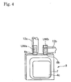
- Fig. 4 is a perspective view showing an electrode connection structure of a secondary battery according to Embodiment 2 of the present invention.
- Fig. 5 is a schematic sectional view of a secondary battery module in which a battery pack consisting of three secondary batteries of Embodiment 2 are contained in a casing;
- Fig. 6 is a schematic diagram showing a state in which tunnel-like wrinkles are formed on a separator in a direction perpendicular to a maximum stretching direction (maximum expanding direction) of the separator when the maximum stretching direction of the separator and a penetrating direction of an electrolytic solution are substantially perpendicular to each other; and
- Fig. 7 is a schematic diagram showing a state in which wrinkles are hardly formed on a separator when a maximum stretching direction of the separator and a penetrating direction of an electrolytic solution are substantially parallel to each other.
- lithium manganate LiMn 2 O 4 positive electrode active material, average particle size of 10 ⁇ m
- acetylene black conductor
- polyvinylidene fluoride binder
- the mixture was applied onto each surface of an aluminum sheet (positive electrode current collector) having a thickness of 15 ⁇ m, at a thickness of about 130 ⁇ m and the resultant was dried, to thereby prepare a sheet-like positive electrode.
- the positive electrode was cut out into a size of 14.3 cm ⁇ 12.9 cm.
- LiPF 6 was dissolved in a concentration of 1 mol/L, to thereby prepare an organic electrolytic solution.
- a commercially available porous stretched polypropylene sheet (UP3025, available from Ube Industries, Ltd.) was used as a separator.
- the separator was cut out into a size of 14.8 cm ⁇ 12.8 cm.
- the separator has expansion anisotropy due to penetration of the nonaqueous electrolytic solution.
- a maximum expanding direction of the separator and a maximum stretching direction of the sheet are substantially parallel to each other, and the directions are also substantially parallel to sides of 14.8 cm.
- the separators (4 sheets), the sheet-like positive electrodes (2 sheets), and the sheet-like negative electrodes (3 sheets) were alternately laminated so that both the outermost layers were the negative electrodes and that the separators were sandwiched by both the positive and negative electrodes, to thereby prepare a laminate consisting of the sheet-like separators and sheet-like electrode pairs.
- Positive electrode terminals were laminated to overlap on each other at a corresponding side
- negative electrode terminals were laminated to overlap on each other at a corresponding side.
- a positive electrode terminal of an aluminum foil of width 3 cm x length 4 cm x thickness 0.15 mm was bonded to the positive electrode through ultrasonic welding in a form pulled out from the side of 14.3 cm of the positive electrode so that the center of the positive electrode terminal was provided at a position of 7.15 cm from edges of the side of the positive electrode.
- a negative electrode terminal of a nickel foil of width 3 cm ⁇ length 4 cm ⁇ thickness 0.15 mm was bonded to the negative electrode through ultrasonic welding in a form pulled out from the side of 14.8 cm of the negative electrode so that the center of the negative electrode terminal was provided at a position of 7.4 cm from edges of the side of the negative electrode.
- a flexible laminate film of a three layer structure having an inner surface layer made of polyethylene on an inner surface side, a middle layer made of an aluminum foil in a middle, and an outer surface layer made of a polyamide resin on an outer surface side was prepared. Two films each obtained by cutting out the film into a size of 17 cm ⁇ 16 cm were collectively used as an outer wrapper pair.
- the laminate and the outer wrapper were laminated into a structure, in which both the inner surface sides of the outer wrapper pair faced each other and both the terminals were pulled out from the two corresponding sides of 17 cm each of the outer wrapper pair. Then, the two sides of 17 cm each were subjected to thermocompression bonding to attach resin layers of the laminate together. Next, one side of the remaining two sides having no terminals pulled out was subjected to thermocompression bonding, to thereby form a bag-like thin-type outer wrapper 4c having the separators sandwiched by the electrode pairs inserted thereinto and a side with an unsealed opened portion. The separators were each sandwiched between the electrode pair at a level in which the separators did not fall and the motion of the separators in a maximum expanding direction was not fixed.
- the thin-type outer wrapper 4c (cell) having the electrode pairs and the separators inserted thereinto was dried at 20 torr and 80°C, for 8 hours in a vacuum dryer because water remained in a secondary battery would adversely affect battery characteristics.
- the outer wrapper was dried in vacuum under heating to simultaneously remove water and prevent oxidation of electrode materials, the copper foil, and the like.
- a predetermined amount of the electrolytic solution was injected into the cell dried in vacuum (Fig. 6).
- the cell was placed in a substantially vertical direction to the maximum expanding direction (maximum stretching direction) of the separators and was left to stand (subjected to aging) for 30 minutes.
- the electrolytic solution was accumulated at the bottom once so that the electrolytic solution penetrated upward in the separators from the bottom. That is, the cell was left to stand so that the maximum expanding direction of the separators and the penetrating direction of the electrolytic solution were substantially parallel to each other.
- defoaming was carried out in a vacuum chamber for removing air bubbles remained in the electrolytic solution.
- the vacuum defoaming required about 5 minutes, and the defoaming step hardly had an effect on wrinkle formation.
- the side of the opened portion was subjected to thermocompression bonding using a vacuum sealer and was sealed into a tightly sealed state, to thereby produce a sheet-like secondary battery 3 of the present invention.
- Fig. 1 shows a perspective view of the sheet-like secondary battery
- Fig. 2 shows a left side view thereof
- Fig. 3 is a sectional view taken along the line III-III of Fig. 1, showing an enlarged view of a portion circled by the circle III of Fig. 2.
- referencenumeral 3 denotes a sheet-like lithium ionsecondarybattery.
- a flexible bag-like outer wrapper 4c contains an internal electrode pair 4a and an electrolytic solution 4b in a tightly sealed state.
- the internal electrode pair 4a is formed by alternately laminating: a sheet-like positive electrode 5b formed by laminating a positive electrode active material on both surfaces of an aluminum positive electrode current collector; and a sheet-like negative electrode 5a formed by laminating a negative electrode active material on both surfaces of a copper negative electrode current collector; through a separator 5c.
- a negative electrode terminal 8a individually connected to the negative electrode 5a of the internal electrode pair 4a passes through the thermocompression bonded portion 7 of the bag-like outer wrapper 4c airtightly, is fixed to the thermocompression bonded portion 7, and projects outward through the thermocompress ion bonded portion 7.
- a pulled out portion is used as an external terminal.
- a positive electrode terminal 8b is individually connected to the positive electrode 5b, and the positive electrode terminal 8b is pulled out from the bag-like outer wrapper 4c airtightly (though not shown).
- Sheet-like bus-bars 12a and 12b made of copper are connected with the positive electrode terminal 8b and the negative electrode terminal 8a, respectively.
- the connection between the negative electrode terminal 8a and the bus-bar 12a and the connection between the positive electrode terminal 8b and the bus-bar 12b are made through ultrasonic welding.
- the positive electrode terminal 8b is made of aluminum as with the positive electrode current collector
- the negative electrode terminal 8a is made of copper or nickel as with the negative electrode current collector. Materials for the terminals are not particularly limited, but electrochemically stable metal materials are desirably used.
- the same material as that used for forming the positive electrode current collector such as aluminum or an aluminum alloy is preferably used as a material for the positive electrode terminal 8b, and at least one of copper and nickel is preferably used as a material for the negative electrode terminal 8a.
- Embodiment 1 employs the terminals 8a and 8b each having a thickness of 150 ⁇ m, but the terminals may be formed into a strip having a thickness of about 50 ⁇ m or more, preferably 100 to 200 ⁇ m, for example.
- the bag-like outer wrapper 4c is formed of a laminate film of a three layer structure having: an inner surface layer 6a made of polyethylene on an inner surface side; a middle layer 6b made of an aluminum foil in a middle; and an outer surface layer 6c made of nylon on an outer surface side.
- the separator 5c may be formed of any material such as a porous film of a single layer or multi layers, nonwoven fabric, or mesh made of polyethylene, polypropylene, or the like as long as the separator has electrical insulation and sufficient strength to ensure close contact with the negative electrode 5a and the positive electrode 5b.
- polypropylene is used from the viewpoints of adhesiveness, safety, and the like.
- a nonaqueous solvent and an electrolytic salt containing lithium used in conventional cells can be used as a solvent and an electrolytic salt used for the electrolytic solution 4b used as an ion conducting material.
- the solvent that can be used include: an ester-based solvent such as ethylene carbonate, propylene carbonate, dimethyl carbonate, diethyl carbonate, or methylethyl carbonate; an ether-based single solvent suchasdimethoxyethane, diethoxyethane, diethyl ether, or dimethyl ether; and a mixed solvent of two kinds of solvents from the same group or from the different groups.
- an ester-based solvent such as ethylene carbonate, propylene carbonate, dimethyl carbonate, diethyl carbonate, or methylethyl carbonate
- an ether-based single solvent suchasdimethoxyethane, diethoxyethane, diethyl ether, or dimethyl ether
- electrolytic salt examples include LiPF 6 , LiAsF 6 , LiClO 4 , LiBF 4 , LiCF 3 SO 3 , LiN(CF 3 SO 2 ) 2 , LiC(CF 3 SO 2 ) 3 , and LiN(C 2 F 5 SO 2 ) 2 .
- LiPF 6 is used.
- the method of producing the sheet-like secondary battery 3 of Embodiment 1 can provide a thin-type secondary battery 3 suitably formed into a module and having no thickness fluctuation, excellent quality stability, and excellent heat radiation properties.
- a high capacity secondary battery can be easily produced, and the secondary battery has advantages of a high degree of freedom in designing the shape thereof and excellent productivity.
- the method of producing the sheet-like secondary battery 3 of Embodiment 1 can provide a high capacity laminated sheet-like secondary battery having excellent heat radiation properties with reduced facility investment cost compared with a secondary battery having the separator 5c fixed under tension in a maximum expanding direction thereof or having the separator 5c fixed by ends such as a wound secondary battery.
- the separators (4 sheets), the sheet-like positive electrodes (2 sheets), and the sheet-like negative electrodes (3 sheets) were alternately laminated in the same manner as in the method of producing the sheet-like secondary battery 3 of Embodiment 1.
- a positive electrode terminal of an aluminum foil of width 3 cm x length 4 cm x thickness 0.15 mm was bonded to the positive electrode through ultrasonic welding in a form pulled out from the side of 14.3 cm of the positive electrode so that the center of the positive electrode terminal was provided at a position of 7.15 cm from edges of the side of the positive electrode.
- a negative electrode terminal of a nickel foil of the same size as that of the positive electrode terminal was bonded to the negative electrode through ultrasonic welding in a form pulled out from the side of 14.8 cm of the negative electrode so that the center of the negative electrode terminal was provided at a position of 7.4 cm from edges of the side of the negative electrode.
- the laminate and the same outer wrapper as that of Embodiment 1 were laminated into a structure in which both the inner surface sides of the outer wrapper pair faced each other, both the terminals were not overlapped on each other, and both the terminals were pulled out from the two corresponding sides of 17 cm each of the outer wrapper pair. Then, the two sides of 17 cm each were subjected to thermocompression bonding to attach resin layers of the laminate together. Next, one side of the remaining two sides having no terminals pulled out was subjected to thermocompression bonding, to thereby form a bag-like thin-type outer wrapper 4c having the separator sandwiched by the electrode pair inserted thereinto and a side with an unsealed opened portion. The separators were each sandwiched between the electrode pair at a level in which the separators did not fall and the motion of the separators in a maximum expanding direction was not fixed.
- Fig. 5 shows a sectional view of the secondary battery module.
- each lithium ion secondary battery (unit battery) forming the battery pack is formed to have a substantially block-shaped contour by alternately laminating a positive electrode having a positive electrode active material applied onto a metal material and a negative electrode having a negative electrode active material applied onto a metal material through a separator.
- the battery pack is formed by connecting two or more of the unit batteries in parallel.
- Unit batteries of the battery pack contained in a container main body (casing) are divided by partition walls provided in the container main body to insulate each unit battery, and are suitable for forming a high capacity secondary battery module.
- the terminal 8a (8b) can efficiently transfer heat of each electrode 4a (4b) to the bus-bar 12a (12b), and the terminal 8a (8b) itself may have a heat radiation effect.
- the secondary battery module of Embodiment 3 has a mode prepared by laminating three sheet-like secondary batteries 3 and connecting them in parallel with each other, for example.
- the number of the sheet-like secondary batteries 3 to be laminated is not limited to three, and may be two, or four or more.
- the connection is not limited to parallel connection, and may be series connection involving connecting the positive electrode and the negative electrode of each sheet-like secondary battery 3 in series, or a combination of series connection and parallel connection.
- the secondary battery module of Embodiment 3 has a simple structure and miniaturization or weight saving thereof is possible. Further, the module can be formed to be thin as required to allow efficient dissipation of heat generated inside the cell to the outside.
- the secondary battery module of Embodiment 3 is expected to be suitably applied to: a relatively small capacity secondary battery used in fields of electrical or electronic devices, communication devices, optical devices, audio equipment, and the like; and a relatively large capacity secondary battery used in fields of electric automobiles and the like, utilizing characteristics of being small-size, lightweight, thin, and having a high degree of freedom in shape.
- the present invention can provide a high capacity thin-type secondary battery suitably formed into a module and having no thickness fluctuation, excellent quality stability, and excellent heat radiation properties.
- the present invention can provide a high capacity thin-type with reduced facility investment cost compared with a secondary battery having the separator fixed under tension in a maximum expanding direction thereof or having the separator fixed by ends such as a wound secondary battery.
Landscapes
- Chemical & Material Sciences (AREA)
- Chemical Kinetics & Catalysis (AREA)
- Electrochemistry (AREA)
- General Chemical & Material Sciences (AREA)
- Engineering & Computer Science (AREA)
- Manufacturing & Machinery (AREA)
- Inorganic Chemistry (AREA)
- Secondary Cells (AREA)
- Cell Separators (AREA)
- Sealing Battery Cases Or Jackets (AREA)
- Connection Of Batteries Or Terminals (AREA)
Abstract
Description
In the accompanying drawings:
Claims (28)
- A method of producing a thin-type secondary battery, comprising the steps of:sandwiching a sheet-like separator having expansion anisotropy due to penetration of an electrolytic solution, by a sheet-like electrode pair;inserting the separator sandwiched by the electrode pair and injecting the electrolytic solution, into a thin-type outer wrapper having an opened portion;penetrating the electrolytic solution into the separator without fixing motion of the separator in a maximum expanding direction and in a state where the maximum expanding direction of the separator and a penetrating direction of the electrolytic solution are substantially parallel to each other; andsealing the opened portion into a tightly sealed state.
- A method of producing a thin-type secondary battery according to claim 1, wherein the electrolytic solution is penetrated into the separator by aging the separator for 10 to 60 minutes in a state where the maximum expanding direction of the separator is substantially vertical, after insertion of the separator and injection of the electrolytic solution.
- A method of producing a thin-type secondary battery according to claim 1 or 2, wherein the electrolytic solution is penetrated into the separator by inserting the separator sandwiched by the electrode pair into the thin-type outer wrapper and injecting the electrolytic solution into the thin-type outer wrapper without fixing motion of the separator in the maximum expanding direction and in a state where the maximum expanding direction of the separator and the penetrating direction of the electrolytic solution are substantially parallel to each other.
- A method according to claim 1, 2 or 3,
wherein the electrolytic solution is penetrated into the separator by injecting the electrolytic solution into the thin-type outer wrapper and inserting the separator sandwiched by the electrode pair into the thin-type outer wrapper having the electrolytic solution injected without fixing motion of the separator in the maximum expanding direction and in a state where the maximum expanding direction of the separator and the penetrating direction of the electrolytic solution are substantially parallel to each other. - A method according to claim 1, 2, 3 or 4,
wherein an angle between the maximum expanding direction of the separator and the penetrating direction of the electrolytic solution is 0 to 30° during penetration of the electrolytic solution. - A method according to any one of claims 1 to 5,
wherein: the separator is formed of a porous stretched sheet; and a maximum stretching direction of the separator is referred to as the maximum expanding direction. - A method according to any one of claims 1 to 6,
wherein: the separator has electrolytic solution penetration rate anisotropy; and the electrolytic solution is penetrated into the separator in a state where a direction of a maximum electrolytic solution penetration rate of the separator and the penetrating direction of the electrolytic solution are substantially perpendicular to each other. - A method of producing a thin-type secondary battery according to claim 7, wherein an angle between the direction of the maximum electrolytic solution penetration rate of the separator and the penetrating direction of the electrolytic solution is 60 to 90° during penetration of the electrolytic solution.
- A method according to any one of claims 1 to 8,
wherein a plurality of the separators each sandwiched by the electrode pair are laminated and inserted into the thin-type outer wrapper. - A method according to any one of claims 1 to 9,
wherein the thin-type outer wrapper comprises a flexible sheet-like outer wrapper. - A method of producing a thin-type secondary battery according to claim 10, wherein the sheet-like outer wrapper has a substantially rectangular shape.
- A method of producing a thin-type secondary battery according to claim 11, wherein: the sheet-like outer wrapper has a bag-like shape with one unsealed side; the electrolytic solution is injected to penetrate into the separator; and the unsealed side is sealed into a tightly sealed state.
- A method of producing a thin-type secondary battery according to claim 11 or 12, wherein: the separator sandwiched by the electrode pair is sandwiched by a substantially rectangular sheet-like outer wrapper pair formed of a laminate film; an edge portion of the sheet-like outer wrapper pair is sealed with one side remained unsealed; the electrolytic solution is injected to penetrate into the separator; and the unsealed side is sealed into a tightly sealed state.
- A method of producing a thin-type secondary battery according to claim 13, wherein: the electrode pair is connected to a positive electrode terminal and a negative electrode terminal; and the separator sandwiched by the electrode pair is sandwiched by the sheet-like outer wrapper pair with both the terminals pulled out.
- A method of producing a thin-type secondary battery according to claim 14, wherein both the terminals are sandwiched by the sheet-like outer wrapper pair with both the terminals pulled out from one side of the sheet-like outer wrapper pair.
- A method of producing a thin-type secondary battery according to claim 15, wherein the one side of the sheet-like outer wrapper pair and the maximum expanding direction of the separator are substantially parallel to each other.
- A method of producing a thin-type secondary battery according to claim 15, wherein the one side of the sheet-like outer wrapper pair and the maximum expanding direction of the separator are substantially perpendicular to each other.
- A method according to claim 14, 15, 16 or 17,
wherein both the terminals are sandwiched by the sheet-like outer wrapper pair with both the terminals pulled out from two corresponding sides of the sheet-like outer wrapper pair. - A method of producing a thin-type secondary battery according to claim 18, wherein the two sides of the sheet-like outer wrapper pair and the maximum expanding direction of the separator are substantially parallel to each other.
- A thin-type secondary battery, comprising:a sheet-like separator having expansion anisotropy due to penetration of an electrolytic solution and having the electrolytic solution penetrated;a sheet-like electrode pair sandwiching the separator; anda thin-type outer wrapper containing the separator and the electrode pair in a tightly sealed state, wherein:the separator is sandwiched between the electrode pair without fixing motion of the separator in a maximum expanding direction; and the maximum expanding direction of the separator and a penetrating direction of the electrolytic solution are substantially parallel to each other during penetration of the electrolytic solution in a production process.
- A thin-type secondary battery according to claim 20, wherein a plurality of the separators each sandwiched by the electrode pair are laminated and contained in the thin-type outer wrapper in a tightly sealed state.
- A battery according to claim 20 or 21,
wherein the thin-type outer wrapper comprises a flexible sheet-like outer wrapper. - A thin-type secondary battery according to claim 22, wherein the sheet-like outer wrapper has a substantially rectangular shape and is provided with a positive electrode terminal and a negative electrode terminal connected to the electrode pair and pulled out from the sheet-like outer wrapper.
- A thin-type secondary battery according to claim 23, wherein: both the terminals are pulled out from one side of the sheet-like outer wrapper; and the maximum expanding direction of the separator and the one side of the sheet-like outer wrapper are substantially parallel to each other.
- A thin-type secondary battery according to claim 24, wherein: both the terminals are pulled out from one side of the sheet-like outer wrapper; and the maximum expanding direction of the separator and the one side of the sheet-like outer wrapper are substantially perpendicular to each other.
- A thin-type secondary battery according to claim 23, wherein: both the terminals are pulled out from two corresponding sides of the sheet-like outer wrapper; and the maximum expanding direction of the separator and the two sides of the sheet-like outer wrapper are substantially parallel to each other.
- A battery according to claim 24, 25 or 26,
wherein both the terminals each have a shape folded back on a line parallel to the side of the sheet-like outer wrapper. - A secondary battery module, comprising: a battery pack formed by connecting the thin-type secondary batteries according to any one of claims 20 to 27 in series and/or parallel with each other; and a casing containing the battery pack.
Applications Claiming Priority (2)
| Application Number | Priority Date | Filing Date | Title |
|---|---|---|---|
| JP2004028564 | 2004-02-04 | ||
| JP2004028564A JP4426861B2 (en) | 2004-02-04 | 2004-02-04 | Thin secondary battery cell, method for manufacturing the same, and secondary battery module |
Publications (3)
| Publication Number | Publication Date |
|---|---|
| EP1562242A2 true EP1562242A2 (en) | 2005-08-10 |
| EP1562242A3 EP1562242A3 (en) | 2010-07-14 |
| EP1562242B1 EP1562242B1 (en) | 2017-10-25 |
Family
ID=34675511
Family Applications (1)
| Application Number | Title | Priority Date | Filing Date |
|---|---|---|---|
| EP05000814.3A Expired - Lifetime EP1562242B1 (en) | 2004-02-04 | 2005-01-17 | Thin-type secondary battery and method of producing the same, and secondary battery module |
Country Status (5)
| Country | Link |
|---|---|
| US (1) | US7914925B2 (en) |
| EP (1) | EP1562242B1 (en) |
| JP (1) | JP4426861B2 (en) |
| KR (1) | KR101144879B1 (en) |
| CN (1) | CN100340027C (en) |
Cited By (2)
| Publication number | Priority date | Publication date | Assignee | Title |
|---|---|---|---|---|
| DE102009006117A1 (en) | 2009-01-26 | 2010-07-29 | Li-Tec Battery Gmbh | Electrochemical energy storage cell |
| DE102009011524A1 (en) | 2009-03-03 | 2010-09-09 | Li-Tec Battery Gmbh | Electric energy storage cell and cell block, electric energy storage device and vehicle with it |
Families Citing this family (20)
| Publication number | Priority date | Publication date | Assignee | Title |
|---|---|---|---|---|
| KR100906253B1 (en) * | 2006-05-01 | 2009-07-07 | 주식회사 엘지화학 | Secondary battery including an electrode terminal having a fracture portion formed when the overcurrent is applied |
| WO2007135790A1 (en) | 2006-05-23 | 2007-11-29 | Incorporated National University Iwate University | Total solid rechargeable battery |
| JP5078282B2 (en) * | 2006-05-31 | 2012-11-21 | 三洋電機株式会社 | Assembled battery |
| KR100876455B1 (en) * | 2006-07-31 | 2008-12-29 | 주식회사 엘지화학 | Pouch type secondary battery with unsealed surplus |
| US8734986B2 (en) * | 2007-07-11 | 2014-05-27 | Nissan Motor Co., Ltd. | Laminate type battery |
| US8835058B2 (en) * | 2010-12-21 | 2014-09-16 | GM Global Technology Operations LLC | Battery separators with variable porosity |
| US9172075B2 (en) | 2010-12-21 | 2015-10-27 | GM Global Technology Operations LLC | Battery separators with variable porosity |
| JP5558338B2 (en) * | 2010-12-27 | 2014-07-23 | 株式会社東芝 | Bonded body, manufacturing method of bonded body, and battery pack |
| JP2013235713A (en) * | 2012-05-09 | 2013-11-21 | Sh Copper Products Corp | Current-collecting copper foil used in lithium ion secondary battery, and lithium ion secondary battery arranged therewith |
| EP2882018B1 (en) * | 2012-07-30 | 2016-12-21 | Nissan Motor Company, Limited | Film member lamination device and method therefor |
| JP2014035954A (en) * | 2012-08-09 | 2014-02-24 | Sanyo Electric Co Ltd | Nonaqueous electrolyte secondary battery |
| US20140370347A1 (en) * | 2013-06-14 | 2014-12-18 | Samsung Sdi Co., Ltd. | Flexible battery |
| DE102014008740A1 (en) | 2014-06-12 | 2015-12-17 | Daimler Ag | Electrochemical energy storage and battery |
| CN106716671B (en) * | 2014-07-31 | 2021-06-18 | 达纳加拿大公司 | Battery cell heat exchanger with graded heat transfer surface |
| CN105720292B (en) * | 2014-12-17 | 2020-07-07 | 精工电子有限公司 | Electrochemical cell and portable device |
| JP6319332B2 (en) * | 2016-01-12 | 2018-05-09 | トヨタ自動車株式会社 | Assembled battery |
| CN108878734B (en) * | 2017-05-12 | 2022-03-22 | 住友化学株式会社 | Insulating porous layer for non-aqueous electrolyte secondary battery |
| KR20190032843A (en) * | 2017-09-20 | 2019-03-28 | 에스케이이노베이션 주식회사 | Battery Module for Secondary Battery and Battery Pack having the Same |
| US20220085449A1 (en) * | 2019-01-18 | 2022-03-17 | Dai Nippon Printing Co., Ltd. | Electricity storage device, electric-powered vehicle, and mehtod of manufacturing an electricity storage device |
| JP7600928B2 (en) | 2021-08-10 | 2024-12-17 | トヨタ自動車株式会社 | Battery manufacturing method |
Family Cites Families (14)
| Publication number | Priority date | Publication date | Assignee | Title |
|---|---|---|---|---|
| JPH07282841A (en) * | 1994-04-05 | 1995-10-27 | Mitsubishi Chem Corp | Lithium ion secondary battery |
| JP3363910B2 (en) * | 1997-03-19 | 2003-01-08 | 旭化成株式会社 | Non-aqueous thin battery |
| JPH11185815A (en) * | 1997-12-16 | 1999-07-09 | Fujitsu Ltd | Battery and method for manufacturing battery |
| JP2000123858A (en) | 1998-10-16 | 2000-04-28 | Japan Storage Battery Co Ltd | Manufacturing method of battery with good airtightness |
| JP2000133244A (en) | 1998-10-26 | 2000-05-12 | Japan Storage Battery Co Ltd | Battery and manufacturing method thereof |
| JP4281129B2 (en) * | 1998-10-28 | 2009-06-17 | 三菱電機株式会社 | Lithium ion secondary battery |
| JP3683144B2 (en) | 1999-12-16 | 2005-08-17 | 日本電気株式会社 | Non-aqueous electrolyte secondary battery with film |
| JP4295908B2 (en) * | 2000-11-06 | 2009-07-15 | 株式会社東芝 | Battery manufacturing apparatus and manufacturing method |
| JP2002298833A (en) * | 2001-03-30 | 2002-10-11 | Shibaura Mechatronics Corp | Manufacturing method of secondary battery and liquid injection method |
| JP2003045495A (en) | 2001-07-27 | 2003-02-14 | Matsushita Electric Ind Co Ltd | Non-aqueous electrolyte secondary battery and method of manufacturing the same |
| JP3965954B2 (en) * | 2001-09-12 | 2007-08-29 | 三菱化学株式会社 | Porous film |
| JP4794099B2 (en) | 2001-09-28 | 2011-10-12 | 東レ東燃機能膜合同会社 | Method for producing polyolefin microporous membrane |
| JP2003109557A (en) * | 2001-09-28 | 2003-04-11 | Mitsubishi Electric Corp | Non-aqueous electrolyte battery and method of manufacturing the same |
| JP3687632B2 (en) * | 2002-06-26 | 2005-08-24 | 日産自動車株式会社 | Thin battery |
-
2004
- 2004-02-04 JP JP2004028564A patent/JP4426861B2/en not_active Expired - Lifetime
-
2005
- 2005-01-17 EP EP05000814.3A patent/EP1562242B1/en not_active Expired - Lifetime
- 2005-01-20 CN CNB2005100043883A patent/CN100340027C/en not_active Expired - Lifetime
- 2005-01-21 US US11/038,141 patent/US7914925B2/en active Active
- 2005-02-03 KR KR1020050009955A patent/KR101144879B1/en not_active Expired - Lifetime
Cited By (4)
| Publication number | Priority date | Publication date | Assignee | Title |
|---|---|---|---|---|
| DE102009006117A1 (en) | 2009-01-26 | 2010-07-29 | Li-Tec Battery Gmbh | Electrochemical energy storage cell |
| WO2010084026A1 (en) | 2009-01-26 | 2010-07-29 | Li-Tec Battery Gmbh | Electrochemical energy storage cell |
| DE102009011524A1 (en) | 2009-03-03 | 2010-09-09 | Li-Tec Battery Gmbh | Electric energy storage cell and cell block, electric energy storage device and vehicle with it |
| WO2010099906A2 (en) | 2009-03-03 | 2010-09-10 | Li-Tech Battery Gmbh | Electrical energy storage cell and cell block, electrical energy storage device and the vehicle comprising the same |
Also Published As
| Publication number | Publication date |
|---|---|
| KR20060041641A (en) | 2006-05-12 |
| JP2005222787A (en) | 2005-08-18 |
| JP4426861B2 (en) | 2010-03-03 |
| US7914925B2 (en) | 2011-03-29 |
| CN1652381A (en) | 2005-08-10 |
| CN100340027C (en) | 2007-09-26 |
| KR101144879B1 (en) | 2012-05-14 |
| EP1562242B1 (en) | 2017-10-25 |
| EP1562242A3 (en) | 2010-07-14 |
| US20050170243A1 (en) | 2005-08-04 |
Similar Documents
| Publication | Publication Date | Title |
|---|---|---|
| EP1562242B1 (en) | Thin-type secondary battery and method of producing the same, and secondary battery module | |
| KR101501337B1 (en) | Bipolar electrode/separator assembly, bipolar battery comprising the same and method of manufacturing the same | |
| CN100359746C (en) | Laminated lithium secondary battery and manufacturing method thereof | |
| KR100443250B1 (en) | Improved process for manufacturing electrochemical cells | |
| EP4057438A1 (en) | Electrode tab bending apparatus and method | |
| US20130177787A1 (en) | Current collector and nonaqueous secondary battery | |
| CN113178656B (en) | battery module | |
| WO2005018038A2 (en) | Rechargeable bipolar high power electrochemical device with reduced monitoring requirement | |
| KR20140026504A (en) | Bipolar electrochemical li-ion battery having increased capacity | |
| CN102047489A (en) | Secondary battery and battery system | |
| KR20130097881A (en) | Method for manufacturing a secondary battery and the secondary battery manufactured thereby | |
| EP1139479B1 (en) | Polymer electrolyte battery and method for producing the same | |
| KR100719713B1 (en) | Lithium ion battery | |
| JP4218792B2 (en) | Non-aqueous secondary battery | |
| JP2004014528A (en) | Battery device | |
| JP2001273930A (en) | Method for manufacturing polymer battery | |
| KR101593268B1 (en) | Secondary battery having plural leads and preparation methode of thereof | |
| JPH11154534A (en) | Lithium ion secondary battery element | |
| JP4433783B2 (en) | Bipolar battery | |
| KR101416805B1 (en) | Folding cell and super capacitor folding type having the same | |
| KR102815262B1 (en) | Pressing jig and method for manufacturing secondary battery using the same | |
| JP2004071438A (en) | Nonaqueous secondary battery | |
| JP2003272710A (en) | Nonaqueous secondary battery | |
| CN113454833A (en) | Electrochemical device and electronic device | |
| KR100514215B1 (en) | Fabrication of stacked type lithium secondary battery with multiple row attachment |
Legal Events
| Date | Code | Title | Description |
|---|---|---|---|
| PUAI | Public reference made under article 153(3) epc to a published international application that has entered the european phase |
Free format text: ORIGINAL CODE: 0009012 |
|
| AK | Designated contracting states |
Kind code of ref document: A2 Designated state(s): AT BE BG CH CY CZ DE DK EE ES FI FR GB GR HU IE IS IT LI LT LU MC NL PL PT RO SE SI SK TR |
|
| AX | Request for extension of the european patent |
Extension state: AL BA HR LV MK YU |
|
| PUAL | Search report despatched |
Free format text: ORIGINAL CODE: 0009013 |
|
| AK | Designated contracting states |
Kind code of ref document: A3 Designated state(s): AT BE BG CH CY CZ DE DK EE ES FI FR GB GR HU IE IS IT LI LT LU MC NL PL PT RO SE SI SK TR |
|
| AX | Request for extension of the european patent |
Extension state: AL BA HR LV MK YU |
|
| RIC1 | Information provided on ipc code assigned before grant |
Ipc: H01M 10/04 20060101ALI20100608BHEP Ipc: H01M 4/26 20060101ALI20100608BHEP Ipc: H01M 4/04 20060101AFI20050617BHEP |
|
| 17P | Request for examination filed |
Effective date: 20101229 |
|
| AKX | Designation fees paid |
Designated state(s): ES PT |
|
| REG | Reference to a national code |
Ref country code: DE Ref legal event code: R108 Effective date: 20110222 Ref country code: DE Ref legal event code: 8566 |
|
| 17Q | First examination report despatched |
Effective date: 20110408 |
|
| RIC1 | Information provided on ipc code assigned before grant |
Ipc: H01M 6/40 20060101ALI20170328BHEP Ipc: H01M 4/583 20100101ALI20170328BHEP Ipc: H01M 2/06 20060101ALI20170328BHEP Ipc: H01M 2/02 20060101ALI20170328BHEP Ipc: H01M 2/16 20060101ALI20170328BHEP Ipc: H01M 10/04 20060101ALI20170328BHEP Ipc: H01M 4/04 20060101AFI20170328BHEP Ipc: H01M 6/46 20060101ALI20170328BHEP Ipc: H01M 4/505 20100101ALI20170328BHEP Ipc: H01M 2/10 20060101ALI20170328BHEP Ipc: H01M 4/26 20060101ALI20170328BHEP |
|
| GRAP | Despatch of communication of intention to grant a patent |
Free format text: ORIGINAL CODE: EPIDOSNIGR1 |
|
| INTG | Intention to grant announced |
Effective date: 20170511 |
|
| RBV | Designated contracting states (corrected) |
Designated state(s): DE ES FR GB PT |
|
| RIN1 | Information on inventor provided before grant (corrected) |
Inventor name: MIYAMOTO, TAKESHI Inventor name: TAKAHASHI, KAZUHIRO Inventor name: OZAWA, KAZUNORI Inventor name: TANJOU, YUUJI |
|
| RAP1 | Party data changed (applicant data changed or rights of an application transferred) |
Owner name: NISSAN MOTOR CO., LTD. Owner name: ENAX, INC. |
|
| GRAS | Grant fee paid |
Free format text: ORIGINAL CODE: EPIDOSNIGR3 |
|
| GRAA | (expected) grant |
Free format text: ORIGINAL CODE: 0009210 |
|
| AK | Designated contracting states |
Kind code of ref document: B1 Designated state(s): DE ES FR GB PT |
|
| REG | Reference to a national code |
Ref country code: GB Ref legal event code: FG4D |
|
| REG | Reference to a national code |
Ref country code: DE Ref legal event code: R096 Ref document number: 602005052927 Country of ref document: DE |
|
| REG | Reference to a national code |
Ref country code: FR Ref legal event code: PLFP Year of fee payment: 14 |
|
| PG25 | Lapsed in a contracting state [announced via postgrant information from national office to epo] |
Ref country code: ES Free format text: LAPSE BECAUSE OF FAILURE TO SUBMIT A TRANSLATION OF THE DESCRIPTION OR TO PAY THE FEE WITHIN THE PRESCRIBED TIME-LIMIT Effective date: 20171025 |
|
| REG | Reference to a national code |
Ref country code: DE Ref legal event code: R097 Ref document number: 602005052927 Country of ref document: DE |
|
| PLBE | No opposition filed within time limit |
Free format text: ORIGINAL CODE: 0009261 |
|
| STAA | Information on the status of an ep patent application or granted ep patent |
Free format text: STATUS: NO OPPOSITION FILED WITHIN TIME LIMIT |
|
| 26N | No opposition filed |
Effective date: 20180726 |
|
| REG | Reference to a national code |
Ref country code: DE Ref legal event code: R082 Ref document number: 602005052927 Country of ref document: DE Representative=s name: VOSSIUS & PARTNER PATENTANWAELTE RECHTSANWAELT, DE Ref country code: DE Ref legal event code: R081 Ref document number: 602005052927 Country of ref document: DE Owner name: ENAX, INC., BUNKYO, JP Free format text: FORMER OWNERS: NISSAN MOTOR CO., LTD., YOKOHAMA-SHI, KANAGAWA-KEN, JP; ENAX, INC., BUNKYO, TOKYO, JP Ref country code: DE Ref legal event code: R081 Ref document number: 602005052927 Country of ref document: DE Owner name: ENVISION AESC JAPAN LTD., ZAMA-SHI, JP Free format text: FORMER OWNERS: NISSAN MOTOR CO., LTD., YOKOHAMA-SHI, KANAGAWA-KEN, JP; ENAX, INC., BUNKYO, TOKYO, JP |
|
| PG25 | Lapsed in a contracting state [announced via postgrant information from national office to epo] |
Ref country code: PT Free format text: LAPSE BECAUSE OF FAILURE TO SUBMIT A TRANSLATION OF THE DESCRIPTION OR TO PAY THE FEE WITHIN THE PRESCRIBED TIME-LIMIT Effective date: 20171025 |
|
| REG | Reference to a national code |
Ref country code: DE Ref legal event code: R081 Ref document number: 602005052927 Country of ref document: DE Owner name: ENVISION AESC JAPAN LTD., ZAMA-SHI, JP Free format text: FORMER OWNERS: ENAX, INC., BUNKYO, TOKYO, JP; ENVISION AESC JAPAN LTD., ZAMA-SHI, KANAGAWA, JP Ref country code: DE Ref legal event code: R081 Ref document number: 602005052927 Country of ref document: DE Owner name: ENAX, INC., BUNKYO, JP Free format text: FORMER OWNERS: ENAX, INC., BUNKYO, TOKYO, JP; ENVISION AESC JAPAN LTD., ZAMA-SHI, KANAGAWA, JP |
|
| REG | Reference to a national code |
Ref country code: DE Ref legal event code: R081 Ref document number: 602005052927 Country of ref document: DE Owner name: ENVISION AESC JAPAN LTD., ZAMA-SHI, JP Free format text: FORMER OWNERS: ENVISION AESC JAPAN LTD., ZAMA-SHI, KANAGAWA, JP; KASUGA PARTNERS CO. LTD., TOKYO, JP Ref country code: DE Ref legal event code: R081 Ref document number: 602005052927 Country of ref document: DE Owner name: ENAX, INC., BUNKYO, JP Free format text: FORMER OWNERS: ENVISION AESC JAPAN LTD., ZAMA-SHI, KANAGAWA, JP; KASUGA PARTNERS CO. LTD., TOKYO, JP Ref country code: DE Ref legal event code: R082 Ref document number: 602005052927 Country of ref document: DE |
|
| REG | Reference to a national code |
Ref country code: GB Ref legal event code: 732E Free format text: REGISTERED BETWEEN 20210902 AND 20210908 |
|
| REG | Reference to a national code |
Ref country code: DE Ref legal event code: R081 Ref document number: 602005052927 Country of ref document: DE Owner name: ENVISION AESC JAPAN LTD., ZAMA-SHI, JP Free format text: FORMER OWNERS: ENAX, INC., BUNKYO, TOKYO, JP; ENVISION AESC JAPAN LTD., ZAMA-SHI, KANAGAWA, JP |
|
| REG | Reference to a national code |
Ref country code: GB Ref legal event code: 732E Free format text: REGISTERED BETWEEN 20230105 AND 20230111 |
|
| P01 | Opt-out of the competence of the unified patent court (upc) registered |
Effective date: 20230331 |
|
| PGFP | Annual fee paid to national office [announced via postgrant information from national office to epo] |
Ref country code: GB Payment date: 20231123 Year of fee payment: 20 |
|
| PGFP | Annual fee paid to national office [announced via postgrant information from national office to epo] |
Ref country code: FR Payment date: 20231122 Year of fee payment: 20 |
|
| PGFP | Annual fee paid to national office [announced via postgrant information from national office to epo] |
Ref country code: DE Payment date: 20231121 Year of fee payment: 20 |
|
| REG | Reference to a national code |
Ref country code: DE Ref legal event code: R071 Ref document number: 602005052927 Country of ref document: DE |
|
| REG | Reference to a national code |
Ref country code: GB Ref legal event code: PE20 Expiry date: 20250116 |
|
| PG25 | Lapsed in a contracting state [announced via postgrant information from national office to epo] |
Ref country code: GB Free format text: LAPSE BECAUSE OF EXPIRATION OF PROTECTION Effective date: 20250116 |