EP1561506A1 - Verfahren und Anordnung zur Reinigung von Faulgas - Google Patents
Verfahren und Anordnung zur Reinigung von Faulgas Download PDFInfo
- Publication number
- EP1561506A1 EP1561506A1 EP05002208A EP05002208A EP1561506A1 EP 1561506 A1 EP1561506 A1 EP 1561506A1 EP 05002208 A EP05002208 A EP 05002208A EP 05002208 A EP05002208 A EP 05002208A EP 1561506 A1 EP1561506 A1 EP 1561506A1
- Authority
- EP
- European Patent Office
- Prior art keywords
- gas
- flow
- silicon compounds
- filter
- arrangement
- Prior art date
- Legal status (The legal status is an assumption and is not a legal conclusion. Google has not performed a legal analysis and makes no representation as to the accuracy of the status listed.)
- Granted
Links
Images
Classifications
-
- B—PERFORMING OPERATIONS; TRANSPORTING
- B01—PHYSICAL OR CHEMICAL PROCESSES OR APPARATUS IN GENERAL
- B01D—SEPARATION
- B01D53/00—Separation of gases or vapours; Recovering vapours of volatile solvents from gases; Chemical or biological purification of waste gases, e.g. engine exhaust gases, smoke, fumes, flue gases, aerosols
- B01D53/02—Separation of gases or vapours; Recovering vapours of volatile solvents from gases; Chemical or biological purification of waste gases, e.g. engine exhaust gases, smoke, fumes, flue gases, aerosols by adsorption, e.g. preparative gas chromatography
- B01D53/04—Separation of gases or vapours; Recovering vapours of volatile solvents from gases; Chemical or biological purification of waste gases, e.g. engine exhaust gases, smoke, fumes, flue gases, aerosols by adsorption, e.g. preparative gas chromatography with stationary adsorbents
- B01D53/0407—Constructional details of adsorbing systems
- B01D53/0415—Beds in cartridges
-
- B—PERFORMING OPERATIONS; TRANSPORTING
- B01—PHYSICAL OR CHEMICAL PROCESSES OR APPARATUS IN GENERAL
- B01D—SEPARATION
- B01D53/00—Separation of gases or vapours; Recovering vapours of volatile solvents from gases; Chemical or biological purification of waste gases, e.g. engine exhaust gases, smoke, fumes, flue gases, aerosols
- B01D53/02—Separation of gases or vapours; Recovering vapours of volatile solvents from gases; Chemical or biological purification of waste gases, e.g. engine exhaust gases, smoke, fumes, flue gases, aerosols by adsorption, e.g. preparative gas chromatography
- B01D53/04—Separation of gases or vapours; Recovering vapours of volatile solvents from gases; Chemical or biological purification of waste gases, e.g. engine exhaust gases, smoke, fumes, flue gases, aerosols by adsorption, e.g. preparative gas chromatography with stationary adsorbents
- B01D53/047—Pressure swing adsorption
-
- C—CHEMISTRY; METALLURGY
- C10—PETROLEUM, GAS OR COKE INDUSTRIES; TECHNICAL GASES CONTAINING CARBON MONOXIDE; FUELS; LUBRICANTS; PEAT
- C10L—FUELS NOT OTHERWISE PROVIDED FOR; NATURAL GAS; SYNTHETIC NATURAL GAS OBTAINED BY PROCESSES NOT COVERED BY SUBCLASSES C10G OR C10K; LIQUIFIED PETROLEUM GAS; USE OF ADDITIVES TO FUELS OR FIRES; FIRE-LIGHTERS
- C10L3/00—Gaseous fuels; Natural gas; Synthetic natural gas obtained by processes not covered by subclass C10G, C10K; Liquefied petroleum gas
- C10L3/06—Natural gas; Synthetic natural gas obtained by processes not covered by C10G, C10K3/02 or C10K3/04
- C10L3/10—Working-up natural gas or synthetic natural gas
- C10L3/101—Removal of contaminants
-
- B—PERFORMING OPERATIONS; TRANSPORTING
- B01—PHYSICAL OR CHEMICAL PROCESSES OR APPARATUS IN GENERAL
- B01D—SEPARATION
- B01D2253/00—Adsorbents used in seperation treatment of gases and vapours
- B01D2253/10—Inorganic adsorbents
- B01D2253/102—Carbon
-
- B—PERFORMING OPERATIONS; TRANSPORTING
- B01—PHYSICAL OR CHEMICAL PROCESSES OR APPARATUS IN GENERAL
- B01D—SEPARATION
- B01D2256/00—Main component in the product gas stream after treatment
- B01D2256/24—Hydrocarbons
- B01D2256/245—Methane
-
- B—PERFORMING OPERATIONS; TRANSPORTING
- B01—PHYSICAL OR CHEMICAL PROCESSES OR APPARATUS IN GENERAL
- B01D—SEPARATION
- B01D2257/00—Components to be removed
- B01D2257/50—Carbon oxides
- B01D2257/504—Carbon dioxide
-
- B—PERFORMING OPERATIONS; TRANSPORTING
- B01—PHYSICAL OR CHEMICAL PROCESSES OR APPARATUS IN GENERAL
- B01D—SEPARATION
- B01D2257/00—Components to be removed
- B01D2257/55—Compounds of silicon, phosphorus, germanium or arsenic
- B01D2257/556—Organic compounds
-
- B—PERFORMING OPERATIONS; TRANSPORTING
- B01—PHYSICAL OR CHEMICAL PROCESSES OR APPARATUS IN GENERAL
- B01D—SEPARATION
- B01D2257/00—Components to be removed
- B01D2257/80—Water
-
- B—PERFORMING OPERATIONS; TRANSPORTING
- B01—PHYSICAL OR CHEMICAL PROCESSES OR APPARATUS IN GENERAL
- B01D—SEPARATION
- B01D2258/00—Sources of waste gases
- B01D2258/02—Other waste gases
- B01D2258/0283—Flue gases
- B01D2258/0291—Flue gases from waste incineration plants
-
- B—PERFORMING OPERATIONS; TRANSPORTING
- B01—PHYSICAL OR CHEMICAL PROCESSES OR APPARATUS IN GENERAL
- B01D—SEPARATION
- B01D2258/00—Sources of waste gases
- B01D2258/05—Biogas
-
- B—PERFORMING OPERATIONS; TRANSPORTING
- B01—PHYSICAL OR CHEMICAL PROCESSES OR APPARATUS IN GENERAL
- B01D—SEPARATION
- B01D2259/00—Type of treatment
- B01D2259/40—Further details for adsorption processes and devices
- B01D2259/40007—Controlling pressure or temperature swing adsorption
- B01D2259/40009—Controlling pressure or temperature swing adsorption using sensors or gas analysers
-
- B—PERFORMING OPERATIONS; TRANSPORTING
- B01—PHYSICAL OR CHEMICAL PROCESSES OR APPARATUS IN GENERAL
- B01D—SEPARATION
- B01D53/00—Separation of gases or vapours; Recovering vapours of volatile solvents from gases; Chemical or biological purification of waste gases, e.g. engine exhaust gases, smoke, fumes, flue gases, aerosols
- B01D53/30—Controlling by gas-analysis apparatus
-
- C—CHEMISTRY; METALLURGY
- C10—PETROLEUM, GAS OR COKE INDUSTRIES; TECHNICAL GASES CONTAINING CARBON MONOXIDE; FUELS; LUBRICANTS; PEAT
- C10L—FUELS NOT OTHERWISE PROVIDED FOR; NATURAL GAS; SYNTHETIC NATURAL GAS OBTAINED BY PROCESSES NOT COVERED BY SUBCLASSES C10G OR C10K; LIQUIFIED PETROLEUM GAS; USE OF ADDITIVES TO FUELS OR FIRES; FIRE-LIGHTERS
- C10L2290/00—Fuel preparation or upgrading, processes or apparatus therefore, comprising specific process steps or apparatus units
- C10L2290/06—Heat exchange, direct or indirect
-
- C—CHEMISTRY; METALLURGY
- C10—PETROLEUM, GAS OR COKE INDUSTRIES; TECHNICAL GASES CONTAINING CARBON MONOXIDE; FUELS; LUBRICANTS; PEAT
- C10L—FUELS NOT OTHERWISE PROVIDED FOR; NATURAL GAS; SYNTHETIC NATURAL GAS OBTAINED BY PROCESSES NOT COVERED BY SUBCLASSES C10G OR C10K; LIQUIFIED PETROLEUM GAS; USE OF ADDITIVES TO FUELS OR FIRES; FIRE-LIGHTERS
- C10L2290/00—Fuel preparation or upgrading, processes or apparatus therefore, comprising specific process steps or apparatus units
- C10L2290/12—Regeneration of a solvent, catalyst, adsorbent or any other component used to treat or prepare a fuel
-
- C—CHEMISTRY; METALLURGY
- C10—PETROLEUM, GAS OR COKE INDUSTRIES; TECHNICAL GASES CONTAINING CARBON MONOXIDE; FUELS; LUBRICANTS; PEAT
- C10L—FUELS NOT OTHERWISE PROVIDED FOR; NATURAL GAS; SYNTHETIC NATURAL GAS OBTAINED BY PROCESSES NOT COVERED BY SUBCLASSES C10G OR C10K; LIQUIFIED PETROLEUM GAS; USE OF ADDITIVES TO FUELS OR FIRES; FIRE-LIGHTERS
- C10L2290/00—Fuel preparation or upgrading, processes or apparatus therefore, comprising specific process steps or apparatus units
- C10L2290/26—Composting, fermenting or anaerobic digestion fuel components or materials from which fuels are prepared
-
- C—CHEMISTRY; METALLURGY
- C10—PETROLEUM, GAS OR COKE INDUSTRIES; TECHNICAL GASES CONTAINING CARBON MONOXIDE; FUELS; LUBRICANTS; PEAT
- C10L—FUELS NOT OTHERWISE PROVIDED FOR; NATURAL GAS; SYNTHETIC NATURAL GAS OBTAINED BY PROCESSES NOT COVERED BY SUBCLASSES C10G OR C10K; LIQUIFIED PETROLEUM GAS; USE OF ADDITIVES TO FUELS OR FIRES; FIRE-LIGHTERS
- C10L2290/00—Fuel preparation or upgrading, processes or apparatus therefore, comprising specific process steps or apparatus units
- C10L2290/46—Compressors or pumps
-
- C—CHEMISTRY; METALLURGY
- C10—PETROLEUM, GAS OR COKE INDUSTRIES; TECHNICAL GASES CONTAINING CARBON MONOXIDE; FUELS; LUBRICANTS; PEAT
- C10L—FUELS NOT OTHERWISE PROVIDED FOR; NATURAL GAS; SYNTHETIC NATURAL GAS OBTAINED BY PROCESSES NOT COVERED BY SUBCLASSES C10G OR C10K; LIQUIFIED PETROLEUM GAS; USE OF ADDITIVES TO FUELS OR FIRES; FIRE-LIGHTERS
- C10L2290/00—Fuel preparation or upgrading, processes or apparatus therefore, comprising specific process steps or apparatus units
- C10L2290/54—Specific separation steps for separating fractions, components or impurities during preparation or upgrading of a fuel
- C10L2290/542—Adsorption of impurities during preparation or upgrading of a fuel
-
- C—CHEMISTRY; METALLURGY
- C10—PETROLEUM, GAS OR COKE INDUSTRIES; TECHNICAL GASES CONTAINING CARBON MONOXIDE; FUELS; LUBRICANTS; PEAT
- C10L—FUELS NOT OTHERWISE PROVIDED FOR; NATURAL GAS; SYNTHETIC NATURAL GAS OBTAINED BY PROCESSES NOT COVERED BY SUBCLASSES C10G OR C10K; LIQUIFIED PETROLEUM GAS; USE OF ADDITIVES TO FUELS OR FIRES; FIRE-LIGHTERS
- C10L2290/00—Fuel preparation or upgrading, processes or apparatus therefore, comprising specific process steps or apparatus units
- C10L2290/54—Specific separation steps for separating fractions, components or impurities during preparation or upgrading of a fuel
- C10L2290/545—Washing, scrubbing, stripping, scavenging for separating fractions, components or impurities during preparation or upgrading of a fuel
-
- C—CHEMISTRY; METALLURGY
- C12—BIOCHEMISTRY; BEER; SPIRITS; WINE; VINEGAR; MICROBIOLOGY; ENZYMOLOGY; MUTATION OR GENETIC ENGINEERING
- C12M—APPARATUS FOR ENZYMOLOGY OR MICROBIOLOGY; APPARATUS FOR CULTURING MICROORGANISMS FOR PRODUCING BIOMASS, FOR GROWING CELLS OR FOR OBTAINING FERMENTATION OR METABOLIC PRODUCTS, i.e. BIOREACTORS OR FERMENTERS
- C12M47/00—Means for after-treatment of the produced biomass or of the fermentation or metabolic products, e.g. storage of biomass
- C12M47/18—Gas cleaning, e.g. scrubbers; Separation of different gases
-
- Y—GENERAL TAGGING OF NEW TECHNOLOGICAL DEVELOPMENTS; GENERAL TAGGING OF CROSS-SECTIONAL TECHNOLOGIES SPANNING OVER SEVERAL SECTIONS OF THE IPC; TECHNICAL SUBJECTS COVERED BY FORMER USPC CROSS-REFERENCE ART COLLECTIONS [XRACs] AND DIGESTS
- Y02—TECHNOLOGIES OR APPLICATIONS FOR MITIGATION OR ADAPTATION AGAINST CLIMATE CHANGE
- Y02A—TECHNOLOGIES FOR ADAPTATION TO CLIMATE CHANGE
- Y02A50/00—TECHNOLOGIES FOR ADAPTATION TO CLIMATE CHANGE in human health protection, e.g. against extreme weather
- Y02A50/20—Air quality improvement or preservation, e.g. vehicle emission control or emission reduction by using catalytic converters
Definitions
- the present invention relates to a method for purifying digester gas according to the preamble of claim 1 or 5 and an arrangement for Purification and combustion of biogas according to the preamble of the claim 10th
- Digester gases in the context of the present invention arise, for example, in Sewage treatment plants, biogas plants and landfills by anaerobic conversion of organic Waste. They contain in addition to methane, nitrogen and carbon dioxide as main components usually also appreciable shares of halogenated and non-halogenated hydrocarbon compounds as well as various silicon compounds different chain lengths, especially higher and low molecular weight siloxanes.
- Digester gases from sewage treatment plants contain predominantly higher molecular weight, nonpolar silicon compounds, while landfill gas also low-molecular degradation products, including dimethylsilanediol and trimethylsilanol, which are more apolar in character. Digester gases are also usually saturated with water vapor.
- digester gas has been used to operate gas engines, especially in Combined heat and power plants, used.
- This use of digester gas prepares however, with the increasing proportion of siloxanes in recent years in the digester gas problems, since these silicon compounds heavy wear, high Expenditure and damage to the gas engines cause.
- the siloxanes lead in the combustion process to the formation of mineral silicon compounds. These can be used as dusts in the cylinder chamber as well as in the lubricating oil like an abrasive and act as glassy in the combustion chamber Lay on layers that occasionally flake off and cause major damage in the engine can cause. Purification of digester gas to remove silicon compounds, especially siloxanes, therefore plays for the use of Digester gas an essential role.
- the present invention has for its object to provide a method for Purification of digester gas and an arrangement for cleaning and incineration specify of biogas, with a particularly economical cleaning, in particular a minimization of the required or exchangeable amount Adsorbents, such as activated carbon, is made possible in a simple manner,
- a basic idea of the present invention is that in particular if necessary, only a partial flow of digester gas through filters with an adsorbent, like activated carbon, and then with the residual current of the Faulgases is mixed again to a mixed stream to the impurity level be able to reduce the mixed flow sufficiently, in particular, limit values for impurities, in particular of silicon compounds, like siloxanes, for a downstream gas engine to be able to.
- the ratio of partial flow to residual flow in dependence the degree of contamination, in particular with siloxanes or other Silicon compounds, adjusted or varied.
- a measurement of relevant impurities proceeds continuously, like silicon compounds, in particular siloxanes, in mixed flow, to comply with a corresponding limit value for impurities and thereby operate a downstream gas engine trouble-free, at the same time cleaning only to the extent necessary can.
- a filter in particular a prefilter, at least partially desorb.
- the vacuum-desorbable prefilter a main filter downstream. So again, a much cheaper Purification of biogas can be achieved because the amount of required or to be exchanged adsorbent can be reduced.
- siloxanes can in principle be removed from the digester gas.
- the adsorbents In practice only a fraction of the theoretically achievable loading capacity reached the adsorbents. The reason for this are the others competing gas components of the digester gas, such as water vapor and hydrocarbons, the adsorbability of the siloxanes in the adsorbents drastically restrict.
- the competing gas components of the digester gas such as water vapor and hydrocarbons
- the competing gas components can now - in contrast to siloxanes - Desorbed again with a relatively high rate of desorption by vacuum become. Accordingly, the at least partial desorption leads contamination of the prefilter by negative pressure to a simple, fast and cost-effective pre-cleaning, with the downstream main filter at least largely of the said competing gas components is spared and thereby at least substantially only to Adsorption of siloxanes and other silicon compounds with high Loading capacity can be used. Accordingly, the adsorbent or replace the activated carbon of the main filter less frequently than in the prior art, which reduces costs and maintenance intervals.
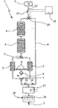
- the proposed arrangement 1 for cleaning and combustion of Digester gas 2 comprises filters 3, 4, which in the illustrated embodiment, an adsorbent, possibly also different adsorbents, preferably activated carbon, for cleaning of the fermentation gas 2 included.
- two filters 3 are provided, which are connected in parallel are and make pre-filters.
- the filters 3 is at least one filter 4 as Downstream main filter.
- two filters 4 are provided, which are connected in series and thus form different filter stages.
- the proposed arrangement 1 further comprises a gas engine 5, the purified fermentation gas 2 can be supplied for combustion.
- the gas engine 5 it is preferably a conventional or adapted internal combustion engine. However, this may be in a broader sense also a gas turbine, a gas-fired cogeneration plant, in particular a Combined heat and power plant, another heater or the like. Act.
- the two prefilters 3 is associated with a vacuum pump 6.
- each pre-filter 3 alternately sealed off and by means of the vacuum pump 6 under negative pressure be set to adsorbed contaminants, especially water vapor and hydrocarbons, at least partially back from the activated carbon desorb, while to be purified digester gas 1 by the other Prefilter 3 is passed. This enables continuous pre-cleaning.
- the arrangement 1 such that the pre-filter 3 substantially only loaded with siloxanes competing gas components, the proportionate can be easily desorbed again by vacuum while the main filter 4 essentially only with siloxanes and possibly other Silicon compounds are loaded.
- This allows a substantial Better utilization of the loading capacity of the adsorbent or the activated carbon with silicon compounds in the main filters 4 as in the state of Technology.
- the adsorbent volume of the main filter 4 is opposite to the Prefilter 3 much larger, in particular at least by a factor of 2, preferably 5 and more preferably at least 10. This allows one very efficient use of the adsorbent or the activated carbon, so that at relatively low cost a very good cleaning performance, in particular a very effective separation of siloxanes and other silicon compounds, is possible.
- the proposed Arrangement 1 a bypass line 9 and an associated valve 10 or another actuator to the filters 3, 4 comprehensive filter stage or to bypass the adsorbent cleaning, if necessary.
- a partial flow 11 of the fermentation gas 2 by the said filter stage or the filters 3, 4 passed and a residual current 12 through the bypass line 9 to the Filter stage or the filters 3, 4 passed around.
- the streams 11, 12 become in particular merged with the valve 10 to a mixed stream 13 and then fed to the gas engine 5 as purified biogas.
- the degree of contamination of the mixed stream 13 is thus dependent on the ratio of the Partial flow 11 reduced to the residual current 12.
- the valve 10 is formed in the illustrated example as a three-way valve and in particular adjustable by means of an associated control device 14, that the ratio of partial flow 11 to residual flow 12 is variable, in particular continuously or in stages between 0 and 1.
- chokes and / or the valve 10 also has a fixed ratio of partial flow 11 to residual flow 12 be set or fixed by example 0.5.
- valve 10 In addition or as an alternative to the indicated valve 10, however, other are also possible constructive solutions possible.
- possibly adjustable Pressure reducers, chokes, flow meters or the like For controlling or Regulation of the ratio of partial flow 11 to residual flow 12 can be used.
- the degree of contamination in particular the proportion of siloxanes and / or other silicon compounds in the fermentation gas to be purified 2, in the partial stream 11, in the residual stream 12 and / or very particularly preferably in Mixed flow 13 measured.
- the arrangement 1 for this purpose corresponding measuring device 15 preferably takes place a continuous Measurement or monitoring of Verunrem Whilesgrads, especially in the Supply line to the gas engine 5, as shown.
- the measuring device 15 to the Control device 14 connected so that an automated control or regulation of the ratio of partial flow 11 to residual flow 12 or a Opening or switching off the bypass line 9 can take place, for example in Dependence on measured values and / or when reaching a limit value.
- the measuring device 15 for controlling and / or displaying a Change the adsorbents of the filters 3 and 4 are used.
- the proposed arrangement 1 additionally a gas wash 16 on.
- the gas scrubber 16 preferably operates with a polar solvents, especially water.
- Very particularly preferred Landfill leachate 17 can be used, which already pollutes already is and requires follow-up treatment.
- the washed and then reduced in its relative humidity Digester gas 2 is then the said adsorbent cleaning or the bypass line 9 for direct transmission to the gas engine 5 is supplied.
- the proposed arrangement 1 and the proposed method allow So an adapted to the particular case optimal cleaning with regard to compliance with an impurity limit Silicon compounds, in particular siloxanes, for the gas engine 5, wherein optimal utilization of the loading capacity of the adsorbent, in particular the activated carbon, with silicon compounds or a minimization of the required Amount of adsorbent, in particular activated carbon, based on the Total flow of biogas 2 is or will be possible.
- Silicon compounds in particular siloxanes
Landscapes
- Chemical & Material Sciences (AREA)
- Oil, Petroleum & Natural Gas (AREA)
- Engineering & Computer Science (AREA)
- General Chemical & Material Sciences (AREA)
- Chemical Kinetics & Catalysis (AREA)
- Analytical Chemistry (AREA)
- Organic Chemistry (AREA)
- Treating Waste Gases (AREA)
- Separation Of Gases By Adsorption (AREA)
- Solid-Sorbent Or Filter-Aiding Compositions (AREA)
Abstract
Description
eine schematische Darstellung einer vorschlagsgemäßen Anordnung zur Reinigung und Verbrennung von Faulgas.
Claims (18)
- Verfahren zur Reinigung von Siliciumverbindungen enthaltendem Faulgas (2) mittels mindestens eines Filters (3, 4), insbesondere mit einem Adsorbens, vorzugsweise Aktivkohle,
dadurch gekennzeichnet, daß ein Teilstrom (11) des Faulgases (2) durch den bzw. die Filter (3, 4) geleitet und danach mit dem Reststrom (12) des nicht durch den bzw. die Filter (3, 4) geleiteten Faulgases (2) wieder zu einem Mischstrom (13) gemischt wird, um den Verunreinigungsgrad an Siliciumverbindungen im Mischstrom (13) in Abhängigkeit vom Verhältnis von Teilstrom (11) zu Reststrom (12) zu reduzieren. - Verfahren nach Anspruch 1, dadurch gekennzeichnet, daß der Grad der Verunreinigung mit Siliciumverbindungen im ungereinigten Faulgas (2), Teilstrom (11) und/oder Mischstrom (13), vorzugsweise fortlaufend gemessen wird.
- Verfahren nach Anspruch 1 oder 2, dadurch gekennzeichnet, daß das Verhältnis von Teilstrom (11) zu Reststrom (12) fest eingestellt oder vorzugsweise in Abhängigkeit vom Grad der Verunreinigung des Mischstroms (13) mit Siliciumverbindungen variiert wird.
- Verfahren nach einem der voranstehenden Ansprüche, dadurch gekennzeichnet, daß das Verhältnis von Teilstrom (11) zu Reststrom (12) zwischen 0 und 1 stufenlos oder in Stufen variierbar ist.
- Verfahren zur Reinigung von Siliciumverbindungen enthaltendem Faulgas (2) mittels eines Vorfilters (3) mit einem Adsorbens, vorzugsweise Aktivkohle, und eines nachgeschalteten Hauptfilters (4), insbesondere nach einem der voranstellenden Ansprüche,
dadurch gekennzeichnet, daß adsorbierte Siliciumverbindungen mittels Unterdruck vom Adsorbens zumindest teilweise desorbiert werden. - Verfahren nach Anspruch 5, dadurch gekennzeichnet, daß zwei Vorfilter (3) abwechselnd, vorzugsweise mittels der selben Unterdruckpumpe (6), unter Unterdruck gesetzt werden, während das Faulgas (2) durch den jeweils anderen Vorfilter (3) geleitet wird.
- Verfahren nach einem der voranstehenden Ansprüche, dadurch gekennzeichnet, daß das Faulgas (2) vor der adsorbierenden Reinigung einer Gaswäsche (16), insbesondere mit einem polaren Lösungsmittel, vorzugsweise Wasser, ganz bevorzugt Deponiesickerwasser (18), unterzogen wird.
- Verfahren nach einem der voranstehenden Ansprüche, dadurch gekennzeichnet, daß die zumindest die relative Feuchte des Faulgases (2) vor der adsorbierenden Reinigung und insbesondere nach einer Gaswäsche (16) reduziert wird, vorzugsweise durch Erwärmen, insbesondere mittels eines Wärmetauschers (18).
- Verfahren nach einem der voranstehenden Ansprüche, dadurch gekennzeichnet, daß der Mischstrom (13) einen verringerten Grad an Verunreinigungen mit Siliciumverbindungen aufweist und einem Gasmotor (5) zur Verbrennung zugeführt wird.
- Anordnung (1) zur Reinigung von Siliciumverbindungen enthaltendem Faulgas (2) und anschließender Verbrennung, wobei die Anordnung (1) mindestens einen Filter (3, 4) mit einem Adsorbens, vorzugsweise Aktivkohle, und einen nachgeordneten Gasmotor (5) zur Verbrennung des gereinigten Faulgases (1) aufweist,
dadurch gekennzeichnet, daß die Anordnung (1) eine Unterdruckpumpe (6) zur zumindest teilweisen Desorption von Siliciumverbindungen vom Adsorbens mindestens eines Filters (3) und/oder eine Bypassleitung (9) und ein zugeordnetes Ventil (10) aufweist, so daß ein Teilstrom (11) des Faulgases (2) durch den bzw. die Filter (3, 4) leitbar und danach mit dem Reststrom (12) des nicht durch den bzw. die Filter (3, 4) geleiteten Faulgases (2) wieder zu einem Mischstrom (13) mischbar ist, um den Verunreinigungsgrad an Siliciumverbindungen im Mischstrom (13) in Abhängigkeit vom Verhältnis von Teilstrom (11) zu Reststrom (12) zu reduzieren. - Anordnung nach Anspruch 10, dadurch gekennzeichnet, daß die Anordnung (1) eine Meßeinrichtung (15) aufweist, um den Grad der Verunreinigung mit Siliciumverbindungen im ungereinigten Faulgas (2), Teilstrom (11), Reststrom (12) und/oder Mischstrom (13) vorzugsweise fortlaufend zu messen.
- Anordnung nach Anspruch 10 oder 11, dadurch gekennzeichnet, daß das Verhältnis von Teilstrom (11) zu Reststrom (12) fest eingestellt oder vorzugsweise in Abhängigkeit vom Grad der Verunreinigung des Mischstroms (13) mit Siliciumverbindungen variierbar ist.
- Anordnung nach einem der Ansprüche 10 bis 12, dadurch gekennzeichnet, daß das Verhältnis von Teilstrom (11) zu Reststrom (12) zwischen 0 und 1 stufenlos oder in Stufen variierbar ist.
- Anordnung nach einem der Ansprüche 10 bis 13, dadurch gekennzeichnet, daß die Anordnung (1) zwei Vorfilter (3) aufweist, die abwechselnd mittels der Unterdruckpumpe (6) unter Unterdruck setzbar sind, während das Faulgas (2) durch den jeweils anderen Vorfilter (3) leitbar ist.
- , Anordnung nach Anspruch 14, dadurch gekennzeichnet, daß den Vorfiltern (3) mindestens ein Hauptfilter (4) nachgeordnet ist.
- Anordnung nach Anspruch 15, dadurch gekennzeichnet, daß das Adsorbensvolumen des Hauptfilters (4) größer als das Adsorbensvolumen jedes Vorfilters (3) ist, insbesondere mindestens um den Faktor 2, vorzugsweise 5, insbesondere 10.
- Anordnung nach einem der Ansprüche 10 bis 14, dadurch gekennzeichnet, daß die Anordnung (1) eine insbesondere mit Wasser, vorzugsweise Deponiesickerwasser (17), arbeitende Gaswäsche (16) aufweist.
- Anordnung nach einem der Ansprüche 10 bis 15, dadurch gekennzeichnet, daß die Anordnung (1) eine Einrichtung, insbesondere einen Wärmetauscher (18), zur Reduzierung der relativen Feuchte des Faulgases (2) vor der adsorbierenden Reinigung und insbesondere nach einer Gaswäsche (16) aufweist.
Priority Applications (1)
| Application Number | Priority Date | Filing Date | Title |
|---|---|---|---|
| DE200520003058 DE202005003058U1 (de) | 2004-02-04 | 2005-02-03 | Anordnung zur Reinigung und Verbrennung von Faulgas |
Applications Claiming Priority (2)
| Application Number | Priority Date | Filing Date | Title |
|---|---|---|---|
| DE102004005626A DE102004005626A1 (de) | 2004-02-04 | 2004-02-04 | Verfahren zur Reinigung von Faulgas und Anordnung zur Reinigung und Verbrennung von Faulgas |
| DE102004005626 | 2004-02-04 |
Publications (2)
| Publication Number | Publication Date |
|---|---|
| EP1561506A1 true EP1561506A1 (de) | 2005-08-10 |
| EP1561506B1 EP1561506B1 (de) | 2007-05-23 |
Family
ID=34673162
Family Applications (1)
| Application Number | Title | Priority Date | Filing Date |
|---|---|---|---|
| EP05002208A Expired - Lifetime EP1561506B1 (de) | 2004-02-04 | 2005-02-03 | Verfahren und Anordnung zur Reinigung von Faulgas |
Country Status (3)
| Country | Link |
|---|---|
| EP (1) | EP1561506B1 (de) |
| AT (1) | ATE362801T1 (de) |
| DE (2) | DE102004005626A1 (de) |
Cited By (6)
| Publication number | Priority date | Publication date | Assignee | Title |
|---|---|---|---|---|
| EP1862212A1 (de) * | 2006-05-29 | 2007-12-05 | Wolfgang Dipl.-Ing. Doczyck | Verfahren und Anordnung zur Reinigung von Faulgas |
| WO2008024329A1 (en) * | 2006-08-22 | 2008-02-28 | Donaldson Company, Inc. | Biogas purification with siloxane removal |
| CN101912719A (zh) * | 2010-08-20 | 2010-12-15 | 广东联塑科技实业有限公司 | 用于hdpe塑料管道生产线的异味气体处理设备及处理方法 |
| US9023755B2 (en) | 2012-12-18 | 2015-05-05 | Cabot Corporation | Siloxane removal from gases using lignite-enhanced activated carbons and adsorbent media used therefor |
| FR3037506A1 (fr) * | 2015-06-17 | 2016-12-23 | Clauger | Procede de lavage d'un effluent gazeux |
| CN119607824A (zh) * | 2024-12-27 | 2025-03-14 | 北京市科学技术研究院城市安全与环境科学研究所 | 一种垃圾处理场臭气污染监测与分级控制装置及方法 |
Families Citing this family (3)
| Publication number | Priority date | Publication date | Assignee | Title |
|---|---|---|---|---|
| AT504325B8 (de) * | 2006-10-03 | 2008-09-15 | Profactor Produktionsforschung | Verfahren zur abtrennung einer komponente aus einem gasgemisch |
| US9803598B2 (en) | 2015-12-21 | 2017-10-31 | Caterpillar Inc. | Air intake system for engine |
| JP2025078141A (ja) * | 2023-11-08 | 2025-05-20 | レール・リキード-ソシエテ・アノニム・プール・レテュード・エ・レクスプロワタシオン・デ・プロセデ・ジョルジュ・クロード | アセチレンガス中の残留溶媒の除去システム |
Citations (3)
| Publication number | Priority date | Publication date | Assignee | Title |
|---|---|---|---|---|
| US5899187A (en) * | 1996-07-11 | 1999-05-04 | Jenbacher Energiesysteme Aktiengesellschaft | Engine arrangement |
| DE19920258A1 (de) * | 1999-05-03 | 2000-11-09 | Faulstich Martin | Naß-Reinigung von Biogas |
| DE10158804C1 (de) * | 2001-11-30 | 2003-07-31 | Fraunhofer Ges Forschung | Verfahren und Vorrichtung zur Reinigung von Faulgasen |
Family Cites Families (3)
| Publication number | Priority date | Publication date | Assignee | Title |
|---|---|---|---|---|
| DE4133869C2 (de) * | 1991-10-12 | 1995-12-14 | Nitsche Manfred | Verfahren zur Reinigung eines mit Kohlenwasserstoffdämpfen beladenen Rohgas- und/oder Abgasstromes unter Rückgewinnung der Kohlenwasserstoffe |
| DE29824595U1 (de) * | 1998-03-13 | 2001-09-13 | Doczyck, Wolfgang, Dipl.-Ing., 46047 Oberhausen | Vorrichtung zum Abscheiden von Siloxanen aus Biogasen |
| DE10226417A1 (de) * | 2002-06-13 | 2003-12-24 | Menerga Appbau Gmbh | Vorrichtung zum Trocknen von Luft in Gebäuden insbesondere in Schwimmhallen |
-
2004
- 2004-02-04 DE DE102004005626A patent/DE102004005626A1/de not_active Withdrawn
-
2005
- 2005-02-03 EP EP05002208A patent/EP1561506B1/de not_active Expired - Lifetime
- 2005-02-03 AT AT05002208T patent/ATE362801T1/de not_active IP Right Cessation
- 2005-02-03 DE DE502005000737T patent/DE502005000737D1/de not_active Expired - Lifetime
Patent Citations (3)
| Publication number | Priority date | Publication date | Assignee | Title |
|---|---|---|---|---|
| US5899187A (en) * | 1996-07-11 | 1999-05-04 | Jenbacher Energiesysteme Aktiengesellschaft | Engine arrangement |
| DE19920258A1 (de) * | 1999-05-03 | 2000-11-09 | Faulstich Martin | Naß-Reinigung von Biogas |
| DE10158804C1 (de) * | 2001-11-30 | 2003-07-31 | Fraunhofer Ges Forschung | Verfahren und Vorrichtung zur Reinigung von Faulgasen |
Non-Patent Citations (1)
| Title |
|---|
| JARR M: "REINIGUNG VON DEPONIEGASEN MITTELS AKTIVKOHLE MIT ANSCHLIESSENDER BIOLOGISCHER REGENERATION", ENTSORGUNGS PRAXIS, BERTERSMANN FACHZEITSCHRIFTEN GMBH, DE, vol. 15, no. 4, April 1997 (1997-04-01), pages 46 - 51, XP000684855, ISSN: 0724-6870 * |
Cited By (7)
| Publication number | Priority date | Publication date | Assignee | Title |
|---|---|---|---|---|
| EP1862212A1 (de) * | 2006-05-29 | 2007-12-05 | Wolfgang Dipl.-Ing. Doczyck | Verfahren und Anordnung zur Reinigung von Faulgas |
| WO2008024329A1 (en) * | 2006-08-22 | 2008-02-28 | Donaldson Company, Inc. | Biogas purification with siloxane removal |
| CN101912719A (zh) * | 2010-08-20 | 2010-12-15 | 广东联塑科技实业有限公司 | 用于hdpe塑料管道生产线的异味气体处理设备及处理方法 |
| US9023755B2 (en) | 2012-12-18 | 2015-05-05 | Cabot Corporation | Siloxane removal from gases using lignite-enhanced activated carbons and adsorbent media used therefor |
| FR3037506A1 (fr) * | 2015-06-17 | 2016-12-23 | Clauger | Procede de lavage d'un effluent gazeux |
| CN119607824A (zh) * | 2024-12-27 | 2025-03-14 | 北京市科学技术研究院城市安全与环境科学研究所 | 一种垃圾处理场臭气污染监测与分级控制装置及方法 |
| CN119607824B (zh) * | 2024-12-27 | 2025-09-09 | 北京市科学技术研究院城市安全与环境科学研究所 | 一种垃圾处理场臭气污染监测与分级控制装置及方法 |
Also Published As
| Publication number | Publication date |
|---|---|
| DE102004005626A1 (de) | 2006-01-12 |
| ATE362801T1 (de) | 2007-06-15 |
| DE502005000737D1 (de) | 2007-07-05 |
| EP1561506B1 (de) | 2007-05-23 |
Similar Documents
| Publication | Publication Date | Title |
|---|---|---|
| DE2257329A1 (de) | Verfahren und vorrichtung zum vermindern der giftigen bestandteile in den abgasen von brennkraftanlagen | |
| EP1561506B1 (de) | Verfahren und Anordnung zur Reinigung von Faulgas | |
| DE10246540B4 (de) | Vorrichtung zur Reinigung von Prozessgas einer Reflowlötanlage | |
| DE10158804C1 (de) | Verfahren und Vorrichtung zur Reinigung von Faulgasen | |
| EP0328708A1 (de) | Verfahren zur Reinigung von Abluft | |
| DE3227375A1 (de) | Verfahren zur reinigung von biologisch abbaubare verunreinigungen enthaltende abluft | |
| DE202005003058U1 (de) | Anordnung zur Reinigung und Verbrennung von Faulgas | |
| EP1862212B1 (de) | Verfahren und Anordnung zur Reinigung von Faulgas | |
| DE3627875C2 (de) | ||
| DE2134275B2 (de) | Entlüftungsanordnung für einen Benzintank von Kraftfahrzeugen | |
| DE102009059147A1 (de) | Kraftstoffzufuhrsystem | |
| DE102008007557A1 (de) | Verfahren und Vorrichtung zur Reinigung und Speicherung von Wasserstoff | |
| DE2455929A1 (de) | Verfahren und anlage zur biologischen reinigung von abwasser | |
| EP0094547A2 (de) | Anlage zur Beseitigung von Sickerwasser und Faulgas in Abfalldeponien | |
| DE102006057910A1 (de) | Verfahren zum Aufbereiten von Altölen und/oder Öl/Wassergemischen oder ähnlichen flüssigen Gemischen | |
| AT509865B1 (de) | Verfahren zur herstellung von roheisen oder flüssigen stahlvorprodukten | |
| DE202006008585U1 (de) | Anordnung zur Reinigung von Faulgas | |
| DE19962791A1 (de) | Verfahren und Vorrichtung zum Reinigen von Rohwasser | |
| EP1934135A1 (de) | Reformersystem sowie verfahren zur reformierung | |
| DE4429208C1 (de) | Verfahren und Anlage zur Abwasseraufbereitung | |
| DE19723564C2 (de) | Vorrichtung zur Gewinnung von Sauerstoff oder Stickstoff | |
| DE4130929A1 (de) | Verfahren zur reinigung eines mit dampf und/oder gasfoermigen schadstoffen, insbes. kohlenwasserstoffen, beladenen abgasstromes | |
| DE102004033588A1 (de) | Verfahren und Vorrichtung zur sorptiven Rückgewinnung halogenierter Kohlenwasserstoffe, vor allem für halogenierte Inhalationsanästhetika | |
| EP0203323B1 (de) | Verfahren und Vorrichtung zur Reinigung und Anreicherung von Deponiegasen | |
| WO2025067957A1 (de) | Vorrichtung und verfahren zur behandlung von abgas eines hauptprozesses |
Legal Events
| Date | Code | Title | Description |
|---|---|---|---|
| PUAI | Public reference made under article 153(3) epc to a published international application that has entered the european phase |
Free format text: ORIGINAL CODE: 0009012 |
|
| AK | Designated contracting states |
Kind code of ref document: A1 Designated state(s): AT BE BG CH CY CZ DE DK EE ES FI FR GB GR HU IE IS IT LI LT LU MC NL PL PT RO SE SI SK TR |
|
| AX | Request for extension of the european patent |
Extension state: AL BA HR LV MK YU |
|
| 17P | Request for examination filed |
Effective date: 20060210 |
|
| AKX | Designation fees paid |
Designated state(s): AT BE BG CH CY CZ DE DK EE ES FI FR GB GR HU IE IS IT LI LT LU MC NL PL PT RO SE SI SK TR |
|
| GRAP | Despatch of communication of intention to grant a patent |
Free format text: ORIGINAL CODE: EPIDOSNIGR1 |
|
| GRAS | Grant fee paid |
Free format text: ORIGINAL CODE: EPIDOSNIGR3 |
|
| GRAA | (expected) grant |
Free format text: ORIGINAL CODE: 0009210 |
|
| AK | Designated contracting states |
Kind code of ref document: B1 Designated state(s): AT BE BG CH CY CZ DE DK EE ES FI FR GB GR HU IE IS IT LI LT LU MC NL PL PT RO SE SI SK TR |
|
| PG25 | Lapsed in a contracting state [announced via postgrant information from national office to epo] |
Ref country code: FI Free format text: LAPSE BECAUSE OF FAILURE TO SUBMIT A TRANSLATION OF THE DESCRIPTION OR TO PAY THE FEE WITHIN THE PRESCRIBED TIME-LIMIT Effective date: 20070523 |
|
| REG | Reference to a national code |
Ref country code: GB Ref legal event code: FG4D Free format text: NOT ENGLISH |
|
| REG | Reference to a national code |
Ref country code: CH Ref legal event code: EP |
|
| REG | Reference to a national code |
Ref country code: IE Ref legal event code: FG4D Free format text: LANGUAGE OF EP DOCUMENT: GERMAN |
|
| REF | Corresponds to: |
Ref document number: 502005000737 Country of ref document: DE Date of ref document: 20070705 Kind code of ref document: P |
|
| PG25 | Lapsed in a contracting state [announced via postgrant information from national office to epo] |
Ref country code: SE Free format text: LAPSE BECAUSE OF FAILURE TO SUBMIT A TRANSLATION OF THE DESCRIPTION OR TO PAY THE FEE WITHIN THE PRESCRIBED TIME-LIMIT Effective date: 20070823 |
|
| PG25 | Lapsed in a contracting state [announced via postgrant information from national office to epo] |
Ref country code: ES Free format text: LAPSE BECAUSE OF FAILURE TO SUBMIT A TRANSLATION OF THE DESCRIPTION OR TO PAY THE FEE WITHIN THE PRESCRIBED TIME-LIMIT Effective date: 20070903 |
|
| PG25 | Lapsed in a contracting state [announced via postgrant information from national office to epo] |
Ref country code: IS Free format text: LAPSE BECAUSE OF FAILURE TO SUBMIT A TRANSLATION OF THE DESCRIPTION OR TO PAY THE FEE WITHIN THE PRESCRIBED TIME-LIMIT Effective date: 20070923 |
|
| NLV1 | Nl: lapsed or annulled due to failure to fulfill the requirements of art. 29p and 29m of the patents act | ||
| PG25 | Lapsed in a contracting state [announced via postgrant information from national office to epo] |
Ref country code: PL Free format text: LAPSE BECAUSE OF FAILURE TO SUBMIT A TRANSLATION OF THE DESCRIPTION OR TO PAY THE FEE WITHIN THE PRESCRIBED TIME-LIMIT Effective date: 20070523 |
|
| GBV | Gb: ep patent (uk) treated as always having been void in accordance with gb section 77(7)/1977 [no translation filed] |
Effective date: 20070523 |
|
| REG | Reference to a national code |
Ref country code: IE Ref legal event code: FD4D |
|
| EN | Fr: translation not filed | ||
| PG25 | Lapsed in a contracting state [announced via postgrant information from national office to epo] |
Ref country code: CZ Free format text: LAPSE BECAUSE OF FAILURE TO SUBMIT A TRANSLATION OF THE DESCRIPTION OR TO PAY THE FEE WITHIN THE PRESCRIBED TIME-LIMIT Effective date: 20070523 Ref country code: IE Free format text: LAPSE BECAUSE OF FAILURE TO SUBMIT A TRANSLATION OF THE DESCRIPTION OR TO PAY THE FEE WITHIN THE PRESCRIBED TIME-LIMIT Effective date: 20070523 Ref country code: PT Free format text: LAPSE BECAUSE OF FAILURE TO SUBMIT A TRANSLATION OF THE DESCRIPTION OR TO PAY THE FEE WITHIN THE PRESCRIBED TIME-LIMIT Effective date: 20071023 Ref country code: DK Free format text: LAPSE BECAUSE OF FAILURE TO SUBMIT A TRANSLATION OF THE DESCRIPTION OR TO PAY THE FEE WITHIN THE PRESCRIBED TIME-LIMIT Effective date: 20070523 Ref country code: NL Free format text: LAPSE BECAUSE OF FAILURE TO SUBMIT A TRANSLATION OF THE DESCRIPTION OR TO PAY THE FEE WITHIN THE PRESCRIBED TIME-LIMIT Effective date: 20070523 Ref country code: SI Free format text: LAPSE BECAUSE OF FAILURE TO SUBMIT A TRANSLATION OF THE DESCRIPTION OR TO PAY THE FEE WITHIN THE PRESCRIBED TIME-LIMIT Effective date: 20070523 Ref country code: BG Free format text: LAPSE BECAUSE OF FAILURE TO SUBMIT A TRANSLATION OF THE DESCRIPTION OR TO PAY THE FEE WITHIN THE PRESCRIBED TIME-LIMIT Effective date: 20070823 |
|
| PG25 | Lapsed in a contracting state [announced via postgrant information from national office to epo] |
Ref country code: SK Free format text: LAPSE BECAUSE OF FAILURE TO SUBMIT A TRANSLATION OF THE DESCRIPTION OR TO PAY THE FEE WITHIN THE PRESCRIBED TIME-LIMIT Effective date: 20070523 Ref country code: LT Free format text: LAPSE BECAUSE OF FAILURE TO SUBMIT A TRANSLATION OF THE DESCRIPTION OR TO PAY THE FEE WITHIN THE PRESCRIBED TIME-LIMIT Effective date: 20070523 |
|
| PLBE | No opposition filed within time limit |
Free format text: ORIGINAL CODE: 0009261 |
|
| STAA | Information on the status of an ep patent application or granted ep patent |
Free format text: STATUS: NO OPPOSITION FILED WITHIN TIME LIMIT |
|
| 26N | No opposition filed |
Effective date: 20080226 |
|
| PG25 | Lapsed in a contracting state [announced via postgrant information from national office to epo] |
Ref country code: GB Free format text: LAPSE BECAUSE OF FAILURE TO SUBMIT A TRANSLATION OF THE DESCRIPTION OR TO PAY THE FEE WITHIN THE PRESCRIBED TIME-LIMIT Effective date: 20070523 Ref country code: GR Free format text: LAPSE BECAUSE OF FAILURE TO SUBMIT A TRANSLATION OF THE DESCRIPTION OR TO PAY THE FEE WITHIN THE PRESCRIBED TIME-LIMIT Effective date: 20070824 Ref country code: IT Free format text: LAPSE BECAUSE OF FAILURE TO SUBMIT A TRANSLATION OF THE DESCRIPTION OR TO PAY THE FEE WITHIN THE PRESCRIBED TIME-LIMIT Effective date: 20070523 |
|
| PG25 | Lapsed in a contracting state [announced via postgrant information from national office to epo] |
Ref country code: RO Free format text: LAPSE BECAUSE OF FAILURE TO SUBMIT A TRANSLATION OF THE DESCRIPTION OR TO PAY THE FEE WITHIN THE PRESCRIBED TIME-LIMIT Effective date: 20070523 |
|
| PG25 | Lapsed in a contracting state [announced via postgrant information from national office to epo] |
Ref country code: FR Free format text: LAPSE BECAUSE OF FAILURE TO SUBMIT A TRANSLATION OF THE DESCRIPTION OR TO PAY THE FEE WITHIN THE PRESCRIBED TIME-LIMIT Effective date: 20080118 |
|
| BERE | Be: lapsed |
Owner name: DOCZYCK, WOLFGANG, DIPL.-ING. Effective date: 20080228 |
|
| PG25 | Lapsed in a contracting state [announced via postgrant information from national office to epo] |
Ref country code: MC Free format text: LAPSE BECAUSE OF NON-PAYMENT OF DUE FEES Effective date: 20080228 |
|
| PG25 | Lapsed in a contracting state [announced via postgrant information from national office to epo] |
Ref country code: EE Free format text: LAPSE BECAUSE OF FAILURE TO SUBMIT A TRANSLATION OF THE DESCRIPTION OR TO PAY THE FEE WITHIN THE PRESCRIBED TIME-LIMIT Effective date: 20070523 |
|
| PG25 | Lapsed in a contracting state [announced via postgrant information from national office to epo] |
Ref country code: BE Free format text: LAPSE BECAUSE OF NON-PAYMENT OF DUE FEES Effective date: 20080228 |
|
| PG25 | Lapsed in a contracting state [announced via postgrant information from national office to epo] |
Ref country code: AT Free format text: LAPSE BECAUSE OF NON-PAYMENT OF DUE FEES Effective date: 20080203 |
|
| PG25 | Lapsed in a contracting state [announced via postgrant information from national office to epo] |
Ref country code: CY Free format text: LAPSE BECAUSE OF FAILURE TO SUBMIT A TRANSLATION OF THE DESCRIPTION OR TO PAY THE FEE WITHIN THE PRESCRIBED TIME-LIMIT Effective date: 20070523 |
|
| REG | Reference to a national code |
Ref country code: CH Ref legal event code: PL |
|
| PG25 | Lapsed in a contracting state [announced via postgrant information from national office to epo] |
Ref country code: LI Free format text: LAPSE BECAUSE OF NON-PAYMENT OF DUE FEES Effective date: 20090228 Ref country code: CH Free format text: LAPSE BECAUSE OF NON-PAYMENT OF DUE FEES Effective date: 20090228 |
|
| PG25 | Lapsed in a contracting state [announced via postgrant information from national office to epo] |
Ref country code: LU Free format text: LAPSE BECAUSE OF NON-PAYMENT OF DUE FEES Effective date: 20080203 Ref country code: HU Free format text: LAPSE BECAUSE OF FAILURE TO SUBMIT A TRANSLATION OF THE DESCRIPTION OR TO PAY THE FEE WITHIN THE PRESCRIBED TIME-LIMIT Effective date: 20071124 |
|
| PG25 | Lapsed in a contracting state [announced via postgrant information from national office to epo] |
Ref country code: TR Free format text: LAPSE BECAUSE OF FAILURE TO SUBMIT A TRANSLATION OF THE DESCRIPTION OR TO PAY THE FEE WITHIN THE PRESCRIBED TIME-LIMIT Effective date: 20070523 |
|
| REG | Reference to a national code |
Ref country code: DE Ref legal event code: R082 Ref document number: 502005000737 Country of ref document: DE Representative=s name: VON ROHR PATENTANWAELTE PARTNERSCHAFT MBB, DE |
|
| PGFP | Annual fee paid to national office [announced via postgrant information from national office to epo] |
Ref country code: DE Payment date: 20150223 Year of fee payment: 11 |
|
| REG | Reference to a national code |
Ref country code: DE Ref legal event code: R119 Ref document number: 502005000737 Country of ref document: DE |
|
| PG25 | Lapsed in a contracting state [announced via postgrant information from national office to epo] |
Ref country code: DE Free format text: LAPSE BECAUSE OF NON-PAYMENT OF DUE FEES Effective date: 20160901 |