EP1561292B1 - Verfahren und vorrichtungen zur rrc-gruppenunterdrückung für mobile kommunikation - Google Patents
Verfahren und vorrichtungen zur rrc-gruppenunterdrückung für mobile kommunikation Download PDFInfo
- Publication number
- EP1561292B1 EP1561292B1 EP04731786A EP04731786A EP1561292B1 EP 1561292 B1 EP1561292 B1 EP 1561292B1 EP 04731786 A EP04731786 A EP 04731786A EP 04731786 A EP04731786 A EP 04731786A EP 1561292 B1 EP1561292 B1 EP 1561292B1
- Authority
- EP
- European Patent Office
- Prior art keywords
- terminal
- message
- connection request
- rrc
- reject message
- Prior art date
- Legal status (The legal status is an assumption and is not a legal conclusion. Google has not performed a legal analysis and makes no representation as to the accuracy of the status listed.)
- Expired - Lifetime
Links
- 238000000034 method Methods 0.000 title claims abstract description 66
- 238000010295 mobile communication Methods 0.000 title description 8
- 230000004044 response Effects 0.000 claims abstract description 20
- 238000004891 communication Methods 0.000 claims description 11
- 230000008569 process Effects 0.000 claims description 8
- 230000000977 initiatory effect Effects 0.000 claims description 3
- 239000002699 waste material Substances 0.000 abstract description 5
- 230000005540 biological transmission Effects 0.000 description 7
- 238000012545 processing Methods 0.000 description 7
- 238000005516 engineering process Methods 0.000 description 5
- 230000006870 function Effects 0.000 description 5
- 230000004913 activation Effects 0.000 description 3
- 238000012546 transfer Methods 0.000 description 3
- 230000007704 transition Effects 0.000 description 3
- 238000010586 diagram Methods 0.000 description 2
- 230000011664 signaling Effects 0.000 description 2
- 230000008859 change Effects 0.000 description 1
- 230000006835 compression Effects 0.000 description 1
- 238000007906 compression Methods 0.000 description 1
- 230000001419 dependent effect Effects 0.000 description 1
- 238000011161 development Methods 0.000 description 1
- 230000018109 developmental process Effects 0.000 description 1
- 238000012423 maintenance Methods 0.000 description 1
- 238000013507 mapping Methods 0.000 description 1
- IQLZWWDXNXZGPK-UHFFFAOYSA-N methylsulfonyloxymethyl methanesulfonate Chemical compound CS(=O)(=O)OCOS(C)(=O)=O IQLZWWDXNXZGPK-UHFFFAOYSA-N 0.000 description 1
- 230000002265 prevention Effects 0.000 description 1
- 230000011218 segmentation Effects 0.000 description 1
- 230000005477 standard model Effects 0.000 description 1
Images


Classifications
-
- H—ELECTRICITY
- H04—ELECTRIC COMMUNICATION TECHNIQUE
- H04B—TRANSMISSION
- H04B7/00—Radio transmission systems, i.e. using radiation field
- H04B7/24—Radio transmission systems, i.e. using radiation field for communication between two or more posts
- H04B7/26—Radio transmission systems, i.e. using radiation field for communication between two or more posts at least one of which is mobile
-
- H—ELECTRICITY
- H04—ELECTRIC COMMUNICATION TECHNIQUE
- H04W—WIRELESS COMMUNICATION NETWORKS
- H04W76/00—Connection management
- H04W76/10—Connection setup
- H04W76/18—Management of setup rejection or failure
-
- H—ELECTRICITY
- H04—ELECTRIC COMMUNICATION TECHNIQUE
- H04W—WIRELESS COMMUNICATION NETWORKS
- H04W4/00—Services specially adapted for wireless communication networks; Facilities therefor
- H04W4/06—Selective distribution of broadcast services, e.g. multimedia broadcast multicast service [MBMS]; Services to user groups; One-way selective calling services
-
- H—ELECTRICITY
- H04—ELECTRIC COMMUNICATION TECHNIQUE
- H04W—WIRELESS COMMUNICATION NETWORKS
- H04W48/00—Access restriction; Network selection; Access point selection
- H04W48/08—Access restriction or access information delivery, e.g. discovery data delivery
- H04W48/12—Access restriction or access information delivery, e.g. discovery data delivery using downlink control channel
Definitions
- the present invention relates to methods and apparatuses for facilitating RRC connection between a terminal and UTRAN in a UMTS (Universal Mobile Telecommunication System) and, more particularly, methods and apparatuses for facilitating RRC group reject through which the UTRAN may perform RRC connection reject using a single message transmitted to a plurality of terminals.
- UMTS Universal Mobile Telecommunication System
- a universal mobile telecommunication system is a European-type, third generation IMT-2000 mobile communication system that has evolved from a European standard known as Global System for Mobile communications (GSM).
- GSM Global System for Mobile communications
- UMTS is intended to provide an improved mobile communication service based upon a GSM core network and wideband code division multiple access (W-CDMA) wireless connection technology.
- W-CDMA wideband code division multiple access
- TSG-RAN radio access network
- UTRAN UMTS terrestrial radio access network
- FIG. 1 illustrates an exemplary basic structure of a general UMTS network. As shown in FIG. 1 , the UMTS is roughly divided into a terminal or user equipment (UE) 10, a UTRAN 20, and a core network (CN) 30.
- UE terminal or user equipment
- CN core network
- the UTRAN 20 includes one or more radio network sub-systems (RNS) 25.
- RNS 25 includes a radio network controller (RNC) 23 and a plurality of Node-Bs (base stations) 21 managed by the RNC 23.
- RNC 23 handles the assignment and management of radio resources and operates as an access point with respect to the core network 30.
- the Node-Bs 21 receive information sent by the physical layer of the terminal 10 through an uplink and transmit data to the terminal 10 through a downlink.
- the Node-Bs 21 operate as access points of the UTRAN 20 for the terminal 10.
- the UTRAN 20 constructs and maintains a radio access bearer (RAB) for communication between the terminal 10 and the core network 30.
- RAB radio access bearer
- the core network 30 requests end-to-end quality of service (QoS) requirements from the RAB, and the RAB supports the QoS requirements the core network 30 has set. Accordingly, by constructing and maintaining the RAB, the UTRAN 20 can satisfy the end-to-end QoS requirements.
- QoS quality of service
- the services provided to a specific terminal 10 are roughly divided into the circuit switched (CS) services and the packet switched (PS) services.
- CS circuit switched
- PS packet switched
- a general voice conversation service is a circuit switched service
- a Web browsing service via an Internet connection is classified as a packet switched (PS) service.
- the RNCs 23 are connected to the mobile switching center (MSC) 31 of the core network 30 and the MSC 31 is connected to the gateway mobile switching center (GMSC) 33 that manages the connection with other networks.
- the RNCs 23 are connected to the serving general packet radio service (GPRS) support node (SGSN) 35 and the gateway GPRS support node (GGSN) 37 of the core network 30.
- GPRS general packet radio service
- SGSN serving general packet radio service
- GGSN gateway GPRS support node
- the SGSN 35 supports the packet communications with the RNCs 23 and the GGSN 37 manages the connection with other packet switched networks, such as the Internet.
- FIG. 2 illustrates a structure of a radio interface protocol between the terminal 10 and the UTRAN 20 according to the 3GPP radio access network standards.
- the radio interface protocol has horizontal layers comprising a physical layer, a data link layer, and a network layer, and has vertical planes comprising a user plane (U-plane) for transmitting user data and a control plane (C-plane) for transmitting control information.
- U-plane user plane
- C-plane control plane
- the user plane is a region that handles traffic information with the user, such as voice or Internet protocol (IP) packets.
- the control plane is a region that handles control information for an interface with a network, maintenance and management of a call, and the like.
- the protocol layers in FIG. 2 can be divided into a first layer (L1), a second layer (L2), and a third layer (L3) based on the three lower layers of an open system interconnection (OSI) standard model.
- OSI open system interconnection
- the first layer (L1) namely, the physical layer, provides an information transfer service to an upper layer by using various radio transmission techniques.
- the physical layer is connected to an upper layer called a medium access control (MAC) layer, via a transport channel.
- MAC medium access control
- the MAC layer and the physical layer exchange data via the transport channel.
- the second layer (L2) includes a MAC layer, a radio link control (RLC) layer, a broadcast/multicast control (BMC) layer, and a packet data convergence protocol (PDCP) layer.
- RLC radio link control
- BMC broadcast/multicast control
- PDCP packet data convergence protocol
- the MAC layer handles mapping between logical channels and transport channels and provides allocation of the MAC parameters for allocation and re-allocation of radio resources.
- the MAC layer is connected to an upper layer called the radio link control (RLC) layer, via a logical channel.
- RLC radio link control
- control channel is used to transmit information of the control plane and a traffic channel is used to transmit information of the user plane.
- a logical channel may be a common channel or a dedicated channel depending on whether the logical channel is shared.
- Logical channels include a dedicated traffic channel (DTCH), a dedicated control channel (DCCH), a common traffic channel (CTCH), a common control channel (CCCH), a broadcast control channel (BCCH), and a paging control channel (PCCH).
- the BCCH provides information including information utilized by a terminal 10 to access a system.
- the PCCH is used by the UTRAN 20 to access a terminal 10.
- the MAC layer is connected to the physical layer by transport channels and can be divided into a MAC-b sub-layer, a MAC-d sub-layer, a MAC-c/sh sub-layer, and a MAC-hs sub-layer according to the type of transport channel being managed.
- the MAC-b sub-layer manages a BCH (Broadcast Channel), which is a transport channel handling the broadcasting of system information.
- the MAC-c/sh sub-layer manages a common transport channel, such as a forward access channel (FACH) or a downlink shared channel (DSCH), which is shared by a plurality of terminals.
- the MAC-d sub-layer manages a dedicated channel (DCH), which is a dedicated transport channel for a specific terminal 10. Accordingly, the MAC-d sublayer is located in a serving RNC (SRNC) that manages a corresponding terminal, and one MAC-d sublayer also exists in each terminal.
- SRNC serving RNC
- the RLC layer supports reliable data transmissions and performs segmentation and concatenation on a plurality of RLC service data units (SDUs) delivered from an upper layer.
- SDUs RLC service data units
- the RLC layer adjusts the size of each RLC SDU in an appropriate manner based upon processing capacity and then creates data units by adding header information thereto.
- the data units called protocol data units (PDUs)
- PDUs are transferred to the MAC layer via a logical channel.
- the RLC layer includes a RLC buffer for storing the RLC SDUs and/or the RLC PDUs.
- the BMC layer schedules a cell broadcast (CB) message transferred from the core network and broadcasts the CB message to terminals 10 positioned in a specific cell or cells.
- CB cell broadcast
- the PDCP layer is located above the RLC layer.
- the PDCP layer is used to transmit network protocol data, such as the IPv4 or IPv6, effectively on a radio interface with a relatively small bandwidth.
- the PDCP layer reduces unnecessary control information used in a wired network, a function called header compression.
- the radio resource control (RRC) layer located at the lowest portion of the third layer (L3) is only defined in the control plane.
- the RRC layer controls the transport channels and the physical channels in relation to setup, reconfiguration, and the release or cancellation of the radio bearers (RBs).
- the RB signifies a service provided by the second layer (L2) for data transmission between the terminal 10 and the UTRAN 20.
- the set up of the RB refers to the process of stipulating the characteristics of a protocol layer and a channel required for providing a specific data service, and setting the respective detailed parameters and operation methods.
- the RRC state refers to whether there exists a logical connection between the RRC of the terminal 10 and the RRC of the UTRAN 20. If there is a connection, the terminal 10 is said to be in RRC connected state. If there is no connection, the terminal 10 is said to be in idle state.
- the UTRAN 20 can determine the existence of a particular terminal within the unit of cells, for example which cell the RRC connected state terminal is in. Thus, the terminal 10 can be effectively controlled.
- the UTRAN 20 cannot determine a terminal 10 in idle state.
- Such idle state terminals 10 can only be determined by the core network 30 to be within a region that is larger than a cell, namely, a location or a routing area. Therefore, the existence of idle state terminals 10 is determined within large regions, and, in order to receive mobile communication services such as voice or data, the idle state terminal must move or change into the RRC connected state.
- a terminal 10 When initially turned on by the user, a terminal 10 searches for an appropriate cell and then remains in idle state within the corresponding cell. When the idle state terminal 10 requires RRC connection, it transitions to the RRC connected state through an RRC connection procedure so that an RRC connection is made with the RRC layer of the UTRAN 20.
- an idle state terminal 10 needs to establish an RRC connection.
- uplink data transmission is necessary, for example when the user attempts to make a call, or when transmitting a response message in reply to a paging message received from the UTRAN 20, an idle state terminal 10 must establish an RRC connection.
- Another situation where an idle terminal 10 needs to establish an RRC connection is in order to receive a multimedia broadcast multicast service (MBMS).
- MBMS multimedia broadcast multicast service
- the 3GPP system can provide multimedia broadcast multicast service (MBMS), which is a new type of service in Release 6.
- MBMS multimedia broadcast multicast service
- the 3GPP TSG SA Service and System Aspect
- a cell broadcast service provided by the conventional Release 99 is limited to a service in which text type short messages are broadcast to a certain area.
- the MBMS service provided by Release 6 is a more advanced service that multicasts multimedia data to terminals (UEs) 10 that have subscribed to the corresponding service in addition to broadcasting multimedia data.
- the MBMS service is a downward-dedicated service that provides a streaming or background service to a plurality of terminals 10 by using a common or dedicated downward channel.
- the MBMS service is divided into a broadcast mode and a multicast rude.
- the MBMS broadcast mode facilitates transmitting multimedia data to every user located in a broadcast area
- the MBMS multicast mode facilitates transmitting multimedia data to a specific user group located in a multicast area.
- the broadcast area signifies a broadcast service available area
- the multicast area signifies a multicast service available area.
- the service announcement provides the terminal 10 with a list of services to be provided and related information.
- the users must receive a service notification provided by the network.
- the service notification provides the terminal 10 with information related to the broadcast data to be transmitted.
- a multicast subscription group is a group of users who have completed a subscription procedure.
- the user can join a multicast group to receive a specific multicast service.
- a multicast group is a group of users that receive a specific multicast service.
- Joining a multicast group also referred to as MBMS multicast activation, means merging with the multicast group that has users who wish to receive the specific multicast service. Accordingly, the user can receive the specific multicast data by joining a multicast group, referred to as MBMS multicast activation.
- the RNC 23 transfers the MBMS user data to the terminal 10 through the base station (Node-B) 21 via the user plane of the UTRAN protocol.
- the UTRAN 20 transfers the MBMS user data by constructing and maintaining a radio access bearer (RAB) for a call communication between the terminal 10 and the core network 30.
- RAB radio access bearer
- the MBMS user data is transferred only by downlink.
- the MBMS radio bearer facilitates transferring, only to a specific terminal 10, the user data of a specific MBMS service transferred by the core network 30 to the UTRAN 20.
- the MBMS radio bearer is divided into a point-to-multipoint type and a point-to-point type.
- the UTRAN 20 selects one of the two types of MBMS radio bearers to provide the MBMS service. To select one of the two MBMS radio bearers, the UTRAN 20 should recognize the number of users, or terminals 10, of a specific MBMS service existing in one cell.
- the UTRAN 20 may count the number of terminals 10 to determine the type of MBMS radio bearer.
- the UTRAN 20 informs the terminals 10 that it is counting the number of terminals when it provides information about the MBMS service via a MBMS common control channel or performs paging for a specific MBMS service group.
- a terminal 10 When a terminal 10 receives a service notification of an MBMS service indicating that counting is being performed on the corresponding service, the terminal establishes a connection between an RRC entity of the terminal and an RRC entity of the UTRAN 20 by transferring an RRC connection request message to the UTRAN through an uplink common channel.
- the RRC connection request message informs the UTRAN 20 that the terminal 10 desires to receive the corresponding MBMS service.
- the UTRAN 20 can recognize users who desire to receive the specific MBMS service in one cell. The UTRAN 20 then sets up an MBMS radio bearer on the basis of the count.
- the UTRAN 20 sets a point-to-point MBMS radio bearer. If the number of users, or terminals 10, existing in a corresponding cell is smaller than a certain threshold value, the UTRAN 20 sets a point-to-point MBMS radio bearer. If the number of users, or terminals 10, existing in a corresponding cell is greater than or equal to a certain threshold value, the UTRAN sets a point-to-multipoint MBMS radio bearer.
- the conventional paging method through which the UTRAN 20 recognizes the number of terminals 10 that desire to receive an MBMS service has shortcomings.
- response messages such as RRC response messages
- RRC response messages are transmitted from terminals 10 that desire to receive the MBMS service.
- the response messages are simultaneously concentrated at uplink channel, resulting in an increase in interference and load on the uplink. Because the UTRAN 20 performs the MBMS service notification to the plurality of terminals 10 using the MBMS common control channel and the corresponding terminals simultaneously inform the UTRAN that they want to receive the corresponding MBMS service through the uplink common channel both the interference and load on the uplink increases.
- the terminals 10 may fail to transmit the response message by the time the UTRAN 20 should set up the MBMS radio bearer.
- the UTRAN 20 receives a number of response messages from the terminals 10 that is above the threshold for setting up the MBMS point-to-multipoint radio bearer, the UTRAN no longer needs to receive additional response messages because all requirements for selecting the radio bearer have been met.
- the UTRAN 20 has already received above a threshold numbed of response messages, the UTRAN continues to receive response messages until the MBMS radio bearer is set. Therefore, uplink radio resources are undesirably wasted.
- the RRC connection procedure is generally divided into three steps; the terminal 10 transmits an RRC connection request message to the UTRAN 20, the UTRAN transmits an RRC connection setup message to the terminal, and the terminal transmits an RRC connection setup complete message to the UTRAN. These steps are illustrated in FIG. 3 .
- FIG. 3 illustrates the conventional art procedure when the UTRAN 20 accepts the RRC connection request of the terminal 10.
- the terminal When an idle state terminal 10 wishes to establish an RRC connection, the terminal first transmits an RRC connection request message to the UTRAN 20.
- the RRC connection request message may include an R RC establishment cause and an initial terminal identifier.
- the initial terminal identifier, or UE identity is an identifier that is unique to a particular terminal 10 and allows that terminal to be identified despite its location anywhere in the world.
- the UTRAN 20 transmits an RRC connection setup message to the terminal 10.
- the RRC connection setup message may include an RNTI (Radio Network Temporary Identity) and radio bearer setup information transmitted together with an initial UE identity.
- the RNTI is a terminal identifier allocated to allow the UTRAN 20 to identify connected state terminals 10. The RNTI is used only when an RRC connection exists and is used only within the UTRAN 20.
- the terminal 10 In response to the RRC connection setup message, the terminal 10 establishes an RRC connection with the UTRAN 20 and transmits an RRC connection setup complete message to the UTRAN 20. After the RRC connection has been established, the terminal 10 uses the RNTI instead of the initial UE identity when communicating with the UTRAN 20.
- the initial UE identity is a unique identifier, frequent use may increase the chances of undesirable exposure. Therefore, the initial UE identity is used briefly only during the initial RRC connection procedure and the RNTI is used thereafter for security reasons.
- FIG. 4 illustrates the conventional art procedure when the UTRAN 20 rejects the RRC connection request of the terminal 10.
- the UTRAN 20 Upon receiving an RRC connection request from the terminal 10, the UTRAN 20 transmits an RRC connection reject message if it is necessary to reject the RRC connection. An initial UE identity and rejection cause are included in the RRC connection reject message to inform the terminal 10 why the RRC connection was rejected. Upon receiving the RRC connection reject message, the terminal 10 returns to an idle state.
- FIG. 5 illustrates a conventional art method 100 for a terminal 10 requesting an RRC connection.
- the method 100 includes transmitting an RRC connection request message (S 110) and operating a timer (S120), determining whether an RRC connection setup message (S 130) or an RRC connection reject message (S 144) is received before the timer expires (S 150), and repeating the process unless an RRC connection setup message or an RRC connection reject message was received or it is determined that a threshold for sending RRC connection requests has been reached (S160).
- the UTRAN 20 Upon receiving an RRC connection request message from the terminal 10, the UTRAN 20 grants the RRC connection request if radio resources are sufficient and transmits an RRC connection setup message to the terminal. Otherwise the UTRAN rejects the RRC connection request and transmits an RRC connection reject message to the terminal 10.
- the initial UE identity included in the RRC connection setup message is compared to the terminal's own identity to determine whether the message was intended for that terminal 10. If the initial UE identity included in the RRC connection setup message is different than that of the terminal 10, the terminal discards the received message and determines whether an RRC connection reject message was received in step S144. If the initial UE identity included in the RRC connection setup message matches that of the terminal 10, the terminal establishes an RRC connection with the UTRAN 20 and transitions to the RRC connected state.
- the RNTI allocated by the UTRAN 20 is stored and an RRC connection setup complete message is transmitted to the UTRAN 20 in step S142.
- the RRC connection setup complete message includes capability information of the terminal 10. Transmission of additional RRC connection request messages is terminated in step S 170.
- the initial UE identity included in the RRC connection reject message is compared to the terminal's own identity to determine whether the message was intended for that terminal 10. If the initial UE identity included in the RRC connection reject message is different than that of the terminal 10, the terminal discards the received message and the state of the timer is checked in step S150. If the initial UE identity included in the RRC connection reject message matches that of the terminal 10, the terminal transitions to the idle state and terminates the RRC connection attempt in step S 170.
- step S 150 Upon determining that the timer has not expired in step S 150, the terminal 10 continues to wait for reception of an RRC connection setup message or an RRC connection reject message. Upon determining that the timer has expired in step S 150, it is determined in step S 160 if a threshold limit for sending RRC connection request messages has been reached.
- the terminal 10 terminates the RRC connection attempt in step S 170. If the threshold limit for sending RRC connection request messages has not been reached, another RRC connection attempt is initiated in step S 110 and the process is repeated.
- radio resources are wasted because transmitting RRC connection reject messages requires an undesirably long time.
- a prime example of such wasted radio resources occurs when providing a multicast service.
- the UTRAN 20 utilizes a multicast service notification procedure to perform a counting operation to determine the total number of terminals 10 wishing to receive a particular multicast service within a particular cell.
- the counting operation is used to determine whether the radio bearer to provide the particular multicast service should be point-to-multipoint or point-to-point. If the number of terminals existing in the corresponding cell is less than a threshold value, a point-to-point radio bearer is set. If the number of terminals is greater than or equal to the threshold, a point-to-multipoint radio bearer is set.
- the terminals 10 wishing to receive the service are all in RRC connected state.
- all terminals 10 wishing to receive the service need not be in RRC connected state because RRC idle state terminals are also able to receive the multicast service through the point-to-multipoint radio bearer.
- selecting the radio bearer type using the counting operation is essential for effectively allocating radio resources. Therefore, the selecting operation is performed before starting a multicast service or periodically during the multicast service.
- those terminals in idle state transmit an RRC connection request message to the UTRAN immediately upon receiving a service notification.
- the UTRAN 20 receives an RRC connection request message after service notification, the number of terminals 10 wishing to receive a particular multicast service within a cell is counted to determine the type of radio bearer.
- RRC connection setup messages are transmitted to a certain number of terminals 10 and RRC connection reject messages are transmitted to the remaining terminals so that some terminals can receive the corresponding service in RRC idle state.
- the UTRAN 20 receives RRC connection request messages from a large number of terminals almost simultaneously after service notification.
- the UTRAN 20 typically rejects a majority of these RRC connection requests. Since each RRC connection reject message informs only one terminal 10 that its RRC connection request has been rejected, an extended period of time and large amount of radio resources are expended to transmit RRC connection reject messages to all corresponding terminals, particularly in a multicast service in which a very large number of terminals are handled.
- a terminal 10 that transmitted an RRC connection request message does not receive an RRC connection setup message or an RRC connection reject message within a certain period of time, the terminal transmits the RRC connection request message again.
- the re-transmission of RRC connection request messages wastes further radio resources since the UTRAN must receive each re-transmitted message.
- ETSI Technical Specification 125 331, Version 5.0.0 of March 2002 specifies the RRC protocol for UMTS.
- EP 1 217 854 A1 relates to a method and apparatus for reducing the signalling load in mobile telecommunication networks, especially for reducing the signalling load to a mobile terminal over the radio interface.
- EP 1 439 668 A2 (prior art falling under Article 54 (3) EPC) relates to a mobile communication system for supporting a multimedia broadcast/multicast service in a non-tracking area.
- EP 1 383 348 A1 (prior art falling under Article 54 (3) EPC) relates to a technology for a mobile user equipment to re-enter a 3GPP service area.
- WO 03/107568 A1 (prior art falling under Article 54(3) EPC) relates to multimedia/broadcast and multicasting services with wireless systems.
- the present invention is directed to methods and apparatuses for facilitating connection between a terminal and a network in a UMTS (Universal Mobile Telecommunication System) by which a single group reject message is utilized by the network to inform a plurality of terminals that their connection request was rejected.
- UMTS Universal Mobile Telecommunication System
- the present invention provides two methods according to independent claims 1 and 6 and two corresponding apparatuses, namely a terminal and a UTRAN, according to independent claims 12 and 13, respectively.
- Various improvements to the methods and apparatuses are defined in the dependent claims.
- FIG. 1 illustrates a network structure of a general 3GPP UMTS system.
- FIG. 2 illustrates an exemplary basic structure of a general UMTS network.
- FIG. 3 illustrates the conventional art procedure when the UTRAN accepts the RRC connection request of a terminal.
- FIG. 4 illustrates the conventional art procedure when the UTRAN rejects the RRC connection request of a terminal.
- FIG. 5 illustrates a conventional art method for processing RRC connection setup messages and RRC connection reject messages.
- FIG. 6 illustrates the procedure when the UTRAN accepts the RRC connection request of a terminal and rejects the RRC connection requests of a plurality of terminals according to the methods of the present invention.
- FIG. 7 illustrates a method for processing RRC connection setup messages and RRC group reject messages according to one embodiment of the present invention.
- FIG. 8 illustrates a method for transmitting an RRC connection setup message and an RRC group reject message according to one embodiment of the present invention.
- FIG. 9 illustrates a terminal for processing RRC connection setup messages and RRC group reject messages according to one embodiment of the present invention.
- FIG. 10 illustrates a network for transmitting RRC connection setup messages and RRC group reject messages according to one embodiment of the present invention.
- the present invention relates to a method and apparatus for facilitating connection between a terminal and a network in a UMTS (Universal Mobile Telecommunication System) by which a single group reject message is utilized by the network to inform a plurality of terminals that their connection request was rejected.
- UMTS Universal Mobile Telecommunication System
- the present invention is illustrated with respect to a mobile communication system such as a UMTS developed by the 3GPP, and specifically an RRC connection associated with an MBMS user service, it is contemplated that the methods and apparatus described herein may also be applied to a communication system operating under similar and/or different standards when it is desired to inform a plurality of terminals that their connection request was rejected without having to send a connection reject message to each terminal such that radio resources are conserved.
- the present invention allows a UTRAN 520 to send the same RRC connection reject message to a plurality of terminals 410 having the same RRC connection reject cause by transmitting a single RRC group reject message containing an initial UE identity list with a plurality of initial UE identities and, optionally, including the RRC connection reject cause.
- a terminal 410 receiving the RRC group reject message first checks to see if its initial UE identity matches any of those in the initial UE identity list. If there is a match, the terminal 410 stops transmitting an RRC connection request and enters an idle state. If there is no match, the terminal 410 continues to wait for an RRC connection setup message or an RRC connection reject message from the UTRAN 520.
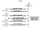
- FIG. 6 illustrates the procedure for transmitting an RRC group reject message utilizing the methods and apparatus of the present invention. Assuming that the UTRAN 520 receives the same RRC connection request message from each of the terminals 410 illustrated (UE1 through UE4), the UTRAN then determines whether to accept or reject each connection request. The condition of radio resources and terminal priority may be considered, among other factors, in making this determination. FIG. 6 illustrates an example where the request from UE 1 is accepted, while the requests from UE2 through UE4 are rejected.
- the UTRAN 520 transmits an RRC connection setup message containing an initial UE identity 1, an RNTI 1, and radio bearer information to UE 1, which has its RRC connection request accepted. Because each terminal 410 is allocated a different RNTI and radio bearer information, an RRC connection setup message must be transmitted to each terminal for which RRC connection is allowed. Therefore, if there are more terminals 410 whose connection request is granted, the UTRAN 520 must transmit additional connection setup messages.
- the UTRAN 520 Simultaneous with the transmission of the RRC connection setup message to UE 1, the UTRAN 520 also transmits an RRC group reject message for UE 2 through UE 4, terminals 410 for which RRC connection has been rejected.
- An initial UE identity list for the terminals 410 is included in the RRC group reject message to allow the terminals to determine if the message is intended for that particular terminal.
- the UTRAN 520 Since the UTRAN 520 must reject the RRC connection requests from a plurality of terminals 410, it is preferable that the RRC group reject message be transmitted to only those terminals having the same reason for rejection, or rejection cause. Furthermore, the UTRAN 520 transmits the RRC group reject message after gathering the requests received from a plurality of terminals 410 over a relatively long period of time, terminals that transmitted their connection requests much earlier than other terminals may have already re-transmitted connection requests because they had not received any response from the UTRAN. This unnecessary re-transmission of requests wastes radio resources. To further conserve radio resources, the UTRAN 520 preferably transmits the RRC group reject message to those terminals 410 that transmitted their requests within a relatively short time period of time. Therefore, the UTRAN 520 generates an RRC group reject message for those terminals that have the same rejection cause and that requested RRC connection simultaneously or within a certain time period.
- UE 2 through UE 4 receive the RRC group reject message and first check the initial UE identity list to see if their identity is included on the list. If a terminal 410 finds its identity on the list, the terminal stops its RRC connection request procedure and enters an idle state. If a terminal 410 does not find its identity on the list, the terminal discards the received RRC group reject message and continues to wait for an RRC connection setup message or another RRC group reject message.
- FIG. 7 illustrates a method 200 for processing RRC connection setup messages and an RRC group reject message in a terminal 410 according to one embodiment of the present invention.
- the method 200 includes initiating a network connection process by transmitting an RRC connection request message (S210) and then reading a common control channel (S225) until either an RRC connection setup message is received (S230) or an RRC group reject message is received (S244). It is contemplated that the method 200 may incorporate methods in the related art, such as timers and re-transmission thresholds, to re-transmit the RRC connection request message if an RRC connection setup message or RRC group reject message is not received.
- step S230 If an RRC connection setup message was received in step S230, a connection to the network is established in step S242 and an RRC connection setup complete message is transmitted to the network. Further re-transmission of RRC connection request messages is ceased in step S270.
- step S244 if an RRC connection setup message is not received, it is determined in step S244 if an RRC group reject message was received. If an RRC group reject message was not received, the terminal 410 continues to wait for an RRC connection setup message or RRC group reject message by again reading the common control channel in step S225. If an RRC group reject message was received, a list of UE identities contained in the RRC group reject message is checked. The UE identities indicate the terminals 410 whose connection requests were rejected.
- step S265 an internal terminal identifier is compared to the list of UE identifiers in the RRC group reject message. If the particular terminal's internal terminal identifier is found in the list, the terminal 410 enters an idle state in step S267 and the network connection process is abandoned, with further re-transmission of RRC connection request messages ceased in step S270. If the particular terminal's internal terminal identifier is not found in the list, the RRC group reject message is discarded and the terminal 410 continues to wait for an RRC connection setup message or RRC group reject message by again reading the common control channel in step S225.
- the RRC connection request may be associated with a user service, such as MDMS multipoint service, and the RRC connection setup messages and RRC group reject message may be directed to terminals 410 subscribing to the service.
- a user service such as MDMS multipoint service
- the RRC connection setup messages and RRC group reject message are received on the same common control channel and the RRC connection request messages are transmitted on an MBMS control channel.
- FIG. 8 illustrates a method 300 for processing RRC connection request messages and generating RRC connection setup messages and an RRC group reject message in a network according to one embodiment of the present invention.
- the method 300 includes receiving an RRC connection request message (S310) and then determining whether or not to grant the RRC connection request (S315).
- step S315 of whether or not to grant the RRC connection request may be in accordance with available radio resources and / or terminal priority. If the RRC connection request is granted, an RRC connection setup message is transmitted in step S330 to the terminal 410 that transmitted the RRC connection request. If the RRC connection request is rejected, a terminal identifier corresponding to the terminal 410 that transmitted the RRC connection request is added, in step S317, to a list of terminal identifiers corresponding to terminals whose RRC connection request was rejected.
- a threshold is utilized in step S319 to determine when to transmit an RRC group reject message. It is contemplated that the threshold is related to a predetermined time period such that the RRC group reject message is transmitted within the predetermined period of time after the first RRC connection request is received in order to prevent terminals 410 from re-transmitting an RRC connection request before they are informed that their previous RRC connection request was rejected.
- RRC group reject message containing the list of terminal identifiers is transmitted in step S344. It is contemplated that the RRC group reject message may include a rejection cause indicating why the connection request was rejected. Preferably the list of terminal identifiers in the RRC group reject message corresponds to terminals 410 having the same rejection cause.
- RRC connection setup messages are transmitted only to those terminals 410 determined to set up a communication connection, while the RRC group reject message is transmitted to all terminals.
- the RRC connection setup messages and the RRC group reject message are transmitted over the same common control channel.
- FIGS. 7 and 8 are only exemplary and may be changed without departing from the intent of the present invention. Furthermore the methods illustrated in FIGS. 7 and 8 may performed by the appropriate software and / or hardware in the UTRAN 520 and in each terminal 410.
- FIG. 9 illustrates a block diagram of a terminal 410 according to the preferred embodiment of the present invention.
- the terminal 410 comprise a processor or digital signal processor 412, RF module 435, power management module 405, antenna 440, battery 455, display 415, keypad 420, memory 430, SIM card 425 (which may be optional), speaker 445 and microphone 450.
- a user enters instructional information, such as a telephone number, for example, by pushing the buttons of a keypad 420 or by voice activation using the microphone 450.
- the microprocessor 412 receives and processes the instructional information to perform the appropriate function, such as to dial the telephone number. Operational data may be retrieved from the Subscriber Identity Module (SIM) card 425 or the memory module 430 to perform the function.
- SIM Subscriber Identity Module
- the processor 412 may display the instructional and operational information on the display 415 for the user's reference and convenience.
- the processor 412 is adapted to perform the method 200 illustrated in FIG. 7 .
- the processor 412 issues instructional information to the RF module 435, to initiate communication, for example, transmit radio signals comprising voice communication data or transmit an RRC connection request message as described herein.
- the RF module 435 comprises a receiver and a transmitter to receive and transmit radio signals.
- An antenna 440 facilitates the transmission and reception of radio signals.
- the RF module 435 may forward and convert the signals to baseband frequency for processing by the processor 412.
- the processed signals may also be transformed into audible or readable information outputted via the speaker 445, for example if the radio signals are an incoming phone call.
- FIG. 10 illustrates a block diagram of a UTRAN 520 according to the preferred embodiment of the present invention.
- the UTRAN 520 includes one or more radio network sub-systems (RNS) 525.
- Each RNS 525 includes a radio network controller (RNC) 523 and a plurality of Node-Bs (base stations) 521 managed by the RNC.
- the RNC 523 handles the assignment and management of radio resources and operates as an access point with respect to the core network 30.
- the RNC 523 is adapted to perform the method 300 illustrated in FIG. 8 .
- the Node-Bs 521 receive information sent by the physical layer of the terminal 410 through an uplink, and transmit data to the terminal through a downlink.
- the Node-Bs 521 operate as access points, or as a transmitter and receiver, of the UTRAN 520 for the terminal 410.
- the present invention facilitates transmitting a single RRC group reject message for rejecting the RRC connection requests of a plurality of terminals 410, thereby minimizing waste of radio resources and providing a quick response to those terminals that transmitted a request. It can be understood that the present invention would be especially advantageous when providing a multicast service to a large number of terminals 410.
Landscapes
- Engineering & Computer Science (AREA)
- Computer Networks & Wireless Communication (AREA)
- Signal Processing (AREA)
- Multimedia (AREA)
- Mobile Radio Communication Systems (AREA)
- Silicon Compounds (AREA)
- Silicates, Zeolites, And Molecular Sieves (AREA)
Claims (13)
- Verfahren (200) zur Kommunikation mit einem Netz eines drahtlosen Kommunikationssystems, wobei das Verfahren aufweist:Senden (S210) einer Verbindungsanforderungsmeldung an das Netz;Empfangen (S214) einer Gruppenunterdrückungsmeldung vom Netz als Antwort auf die gesendete Verbindungsanforderungsmeldung, wobei die Gruppenunterdrückungsmeldung eine Endgeräte-Identitätsliste mit einer Mehrzahl Endgeräte-Kennzeichnungen enthält; undPrüfen (S265), ob eine der Mehrzahl Endgeräte-Kennzeichnungen der Endgeräte-Identitätsliste mit einer internen Endgeräte-Kennzeichnung übereinstimmt;wobei das Verfahren dadurch gekennzeichnet ist, dassdie Verbindungsanforderungsmeldung eine Funkressourcensteuerungs-, kurz RRC, Verbindungsanforderungsmeldung ist;die Gruppenunterdrückungsmeldung eine RRC-Gruppenunterdrückungsmeldung ist und die Gruppenunterdrückungsmeldung ferner eine Ursache für die RRC-Verbindungsunterdrückung enthält;die Ursache der RRC-Verbindungsunterdrückung die gleich ist für alle Endgeräte, die den Endgeräte-Kennzeichnungen der Endgeräte-Identitätsliste in der Gruppenunterdrückungsmeldung entsprechen; unddie Gruppenunterdrückungsmeldung innerhalb einer vorgegebenen Zeitspanne nach dem Senden der Verbindungsanforderungsmeldung empfangen wird.
- Verfahren nach Anspruch 1, bei dem dann, wenn eine der Endgeräte-Kennzeichnungen der Endgeräte-Identitätsliste im Prüfschritt mit der internen Endgeräte-Kennzeichnung übereinstimmt, das Senden der Verbindungsanforderungsmeldung an das Netz beendet (S270) wird und der Eintritt (S267) in einen Ruhezustand erfolgt.
- Verfahren nach Anspruch 1, bei dem dann, wenn eine der Endgeräte-Kennzeichnungen der Endgeräte-Identitätsliste im Prüfschritt nicht mit der internen Endgeräte-Kennzeichnung übereinstimmt, auf eine Verbindungsaufbaumeldung oder eine weitere Gruppenunterdrückungsmeldung vom Netz gewartet (S225) wird.
- Verfahren nach Anspruch 1, bei dem die Verbindungsanforderungsmeldung an das Netz gesendet wird, um einen einem Teilnehmerdienst zugeordneten Netzverbindungsprozess einzuleiten.
- Verfahren nach Anspruch 4, bei dem der Teilnehmerdienst einen MBMS-Dienst umfasst.
- Verfahren (300) zur Kommunikation mit einer Mehrzahl Endgeräte eines drahtlosen Kommunikationssystems, wobei das Verfahren aufweist:Empfangen (S310) einer oder mehrerer Verbindungsanforderungsmeldungen von der Mehrzahl Endgeräte; undSenden (S344) einer Gruppenunterdrückungsmeldung an die Mehrzahl Endgeräte als Antwort auf die empfangene eine oder die empfangenen mehreren Verbindungsanforderungsmeldungen, wobei die Gruppenunterdrückungsmeldung eine Endgeräte-Identitätsliste mit einer Mehrzahl Endgerätekennzeichnungen enthält;wobei das Verfahren dadurch gekennzeichnet ist, dassdie eine oder die mehreren Verbindungsanforderungsmeldungen Funkressourcensteuerungs-, kurz RRC, Verbindungsanforderungsmeldungen sind;die Gruppenunterdrückungsmeldung eine RRC-Gruppenunterdrückungsmeldung ist und die Gruppenunterdrückungsmeldung ferner eine Ursache für die RRC-Verbindungsunterdrückung enthält;die Ursache der RRC-Verbindungsunterdrückung die gleich ist für alle Endgeräte, die den Endgeräte-Kennzeichnungen der Endgeräte-Identitätsliste in der Gruppenunterdrückungsmeldung entsprechen; unddie Gruppenunterdrückungsmeldung innerhalb einer vorgegebenen Zeitspanne nach dem Senden der Verbindungsanforderungsmeldung gesendet wird.
- Verfahren nach Anspruch 6, das ferner
das Bestimmen (S315) umfasst welche Verbindungsanforderungen erfüllt und welche Verbindungsanforderungen nach dem Empfangsschritt unterdrückt werden. - Verfahren nach Anspruch 7, bei dem die Mehrzahl Endgerätekennzeichnungen der Endgeräte-Identitätsliste ein entsprechendes Endgerät angibt, dessen Verbindungsanforderung unterdrückt wird.
- Verfahren nach Anspruch 6, bei dem die eine oder die mehreren Verbindungsanforderungsmeldungen dazu dienen, einen einem Teilnehmerdienst zugeordneten Netzverbindungsprozess einzuleiten.
- Verfahren nach Anspruch 9, bei dem der Teilnehmerdienst einen Punkt-zu-Mehrpunkt-Dienst umfasst.
- Verfahren nach Anspruch 7, bei dem die Bestimmung (S315), welche der einen oder der mehreren Verbindungsanforderungen erfüllt und welche der einen oder der mehreren Verbindungsanforderungen unterdrückt werden, gemäß verfügbaren Funkressourcen oder/und dem jeweiligen Endgerät erfolgt.
- Endgerät (410) zur Kommunikation mit einem Netz eines drahtlosen Kommunikationssystems, wobei das Endgerät (410) aufweist:ein Hochfrequenz-, kurz HF, Modul (435) zum Senden einerVerbindungsanforderungsmeldung an das Netz und zum Empfangen einer Gruppenunterdrückungsmeldung vom Netz als Antwort auf die gesendete Verbindungsanforderungsmeldung, wobei die Gruppenunterdrückungsmeldung eine Endgeräte-Identitätsliste mit einer Mehrzahl Endgeräte-Kennzeichnungen enthält; undeinen Prozessor (412), der eingerichtet ist, um zu prüfen (S265), ob eine der Mehrzahl Endgeräte-Kennzeichnungen der Endgeräte-Identitätsliste mit einer internen Endgeräte-Kennzeichnung übereinstimmt;dadurch gekennzeichnet, dass:die Verbindungsanforderungsmeldung eine Funkressourcensteuerungs-, kurz RRC, Verbindungsanforderungsmeldung ist;die Gruppenunterdrückungsmeldung eine RRC-Gruppenunterdrückungsmeldung ist und die Gruppenunterdrückungsmeldung ferner eine Ursache für die RRC-Verbindungsunterdrückung enthält;die Ursache der RRC-Verbindungsunterdrückung die gleich ist für alle Endgeräte, die den Endgeräte-Kennzeichnungen der Endgeräte-Identitätsliste in der Gruppenunterdrückungsmeldung entsprechen; unddas Endgerät (410) dazu eingerichtet ist, die Gruppenunterdrückungsmeldung innerhalb einer vorgegebenen Zeitspanne nach dem Senden der Verbindungsanforderungsmeldung zu empfangen.
- Terrestrisches UMTS-Funkzugangsnetz, kurz UTRAN, (520) zur Kommunikation mit einer Mehrzahl Endgeräte eines drahtlosen Kommunikationssystems, wobei das UTRAN (520) umfasst:ein oder mehrere Funknetz-Untersysteme, kurz RNS, (525), wobei jedes eine Funknetzsteuerung, kurz RNC, (523) und eine Mehrzahl B-Knoten (521) aufweist, die von der RNC (523) verwaltet werden, wobei das UTRAN eingerichtet ist zum:Empfangen (S310) einer oder mehrerer Verbindungsanforderungsmeldungen von der Mehrzahl Endgeräte; undSenden (S344) einer Gruppenunterdrückungsmeldung an die Mehrzahl Endgeräte als Antwort auf die empfangene eine oder die empfangenen mehreren Verbindungsanforderungsmeldungen, wobei die Gruppenunterdrückungsmeldung eine Endgeräte-Identitätsliste mit einer Mehrzahl Endgerätekennzeichnungen enthält;dadurch gekennzeichnet, dassdie eine oder die mehreren Verbindungsanforderungsmeldungen Funkressourcensteuerungs-, kurz RRC, Verbindungsanforderungsmeldungen sind;die Gruppenunterdrückungsmeldung eine RRC-Gruppenunterdrückungsmeldung ist und die Gruppenunterdrückungsmeldung ferner eine Ursache für die RRC-Verbindungsunterdrückung enthält;die Ursache der RRC-Verbindungsunterdrückung die gleich ist für alle Endgeräte, die den Endgeräte-Kennzeichnungen der Endgeräte-Identitätsliste in der Gruppenunterdrückungsmeldung entsprechen; unddas UTRAN (520) dazu eingerichtet ist, die Gruppenunterdrückungsmeldung innerhalb einer vorgegebenen Zeitspanne nach dem Empfang der einen oder der mehreren Verbindungsanforderungsmeldungen zu senden.
Applications Claiming Priority (3)
| Application Number | Priority Date | Filing Date | Title |
|---|---|---|---|
| KR1020030029468A KR100959719B1 (ko) | 2003-05-09 | 2003-05-09 | 이동통신시스템에서의 무선자원관리 방법 |
| KR2003029468 | 2003-05-09 | ||
| PCT/KR2004/001064 WO2004100401A1 (en) | 2003-05-09 | 2004-05-07 | Rrc group reject method and apparatus for mobile communications |
Publications (3)
| Publication Number | Publication Date |
|---|---|
| EP1561292A1 EP1561292A1 (de) | 2005-08-10 |
| EP1561292A4 EP1561292A4 (de) | 2010-04-07 |
| EP1561292B1 true EP1561292B1 (de) | 2011-04-13 |
Family
ID=33411665
Family Applications (1)
| Application Number | Title | Priority Date | Filing Date |
|---|---|---|---|
| EP04731786A Expired - Lifetime EP1561292B1 (de) | 2003-05-09 | 2004-05-07 | Verfahren und vorrichtungen zur rrc-gruppenunterdrückung für mobile kommunikation |
Country Status (7)
| Country | Link |
|---|---|
| US (1) | US7613473B2 (de) |
| EP (1) | EP1561292B1 (de) |
| KR (1) | KR100959719B1 (de) |
| CN (1) | CN1720677B (de) |
| AT (1) | ATE505930T1 (de) |
| DE (1) | DE602004032208D1 (de) |
| WO (1) | WO2004100401A1 (de) |
Families Citing this family (43)
| Publication number | Priority date | Publication date | Assignee | Title |
|---|---|---|---|---|
| KR20050014984A (ko) * | 2003-08-01 | 2005-02-21 | 삼성전자주식회사 | 멀티미디어 브로드캐스트/멀티캐스드 서비스를 제공하는이동통신시스템에서 무선 자원 연결을 요청하는 메시지를재전송하는 방법 |
| US7636323B2 (en) * | 2005-06-14 | 2009-12-22 | Broadcom Corporation | Method and system for handling connection setup in a network |
| US20070004438A1 (en) * | 2005-07-01 | 2007-01-04 | Alec Brusilovsky | Method and apparatus enabling PTT (push-to-talk) communications between legacy PSTN, cellular and wireless 3G terminals |
| CN100421482C (zh) * | 2005-07-15 | 2008-09-24 | 华为技术有限公司 | 一种更新A2p接口承载参数的方法 |
| JP4354437B2 (ja) * | 2005-07-27 | 2009-10-28 | 株式会社エヌ・ティ・ティ・ドコモ | 移動局、無線アクセスネットワーク装置および移動通信システム並びに通信方法 |
| KR100761700B1 (ko) * | 2006-01-26 | 2007-09-28 | 삼성전자주식회사 | 이동통신 단말기에서 호 연결 방법 |
| CN100446621C (zh) * | 2006-03-22 | 2008-12-24 | 华为技术有限公司 | 建立无线资源控制连接的方法及无线网络控制器 |
| WO2008052383A1 (en) * | 2006-10-30 | 2008-05-08 | Huawei Technologies Co., Ltd. | Load control of ue mbms measurement reporting |
| US8515478B2 (en) * | 2006-12-18 | 2013-08-20 | Qualcomm Incorporated | Fast state transition for a UE with reconfiguration over paging |
| KR101429276B1 (ko) | 2007-04-30 | 2014-08-12 | 엘지전자 주식회사 | 이동통신 시스템의 무선자원 할당 제어방법 |
| EP2096884A1 (de) * | 2008-02-29 | 2009-09-02 | Koninklijke KPN N.V. | Telekommunikationsnetzwerk und Verfahren für den zeitbasierten Netzwerkzugang |
| WO2010072035A1 (zh) * | 2008-12-26 | 2010-07-01 | 华为终端有限公司 | 选择网络的方法、用户设备及系统 |
| US8095075B2 (en) * | 2009-03-10 | 2012-01-10 | Telefonaktiebolaget Lm Ericsson (Publ) | System and method of detecting a sleeping cell and remedying detected conditions in a telecommunication network |
| US20100302950A1 (en) * | 2009-05-30 | 2010-12-02 | Zhao Ray R | Timer adjustment for load control |
| US9078192B2 (en) * | 2009-10-30 | 2015-07-07 | Aruba Networks, Inc. | Balancing clients across bands in a single access point |
| KR101810260B1 (ko) * | 2010-02-12 | 2017-12-18 | 인터디지탈 패튼 홀딩스, 인크 | 상향링크 랜덤 액세스 채널 전송을 최적화하는 방법 및 장치 |
| KR101878000B1 (ko) | 2010-04-02 | 2018-07-12 | 인터디지탈 패튼 홀딩스, 인크 | 릴레이 노드를 통한 통신을 지원하기 위한 방법 및 장치 |
| CN102291679B (zh) * | 2010-06-18 | 2013-09-25 | 电信科学技术研究院 | 一种mbms承载释放通知的方法和设备 |
| CN102457981B (zh) * | 2010-10-22 | 2015-04-08 | 宏碁股份有限公司 | 移动通讯装置、系统、以及连线建立方法 |
| CN102469548A (zh) * | 2010-11-05 | 2012-05-23 | 中兴通讯股份有限公司 | 接入处理方法、装置及系统 |
| TWI484852B (zh) | 2011-01-10 | 2015-05-11 | Inst Information Industry | 無線裝置、基地台及其通訊控制方法 |
| EP2696642A4 (de) * | 2011-04-08 | 2015-12-30 | Lg Electronics Inc | Verfahren zur herstellung einer verbindung zwischen einer benutzervorrichtung und einem netzwerk in einem drahtlosen kommunikationssystem und vorrichtung dafür |
| CN102761981A (zh) * | 2011-04-29 | 2012-10-31 | 华为技术有限公司 | 建立rrc连接的方法及系统 |
| US8918519B1 (en) * | 2011-07-29 | 2014-12-23 | Juniper Networks, Inc. | Delayed network interface selection |
| CN103024736A (zh) * | 2011-09-28 | 2013-04-03 | 国民技术股份有限公司 | 一种通信连接方法及装置 |
| CN108462972A (zh) | 2012-03-16 | 2018-08-28 | Lg 电子株式会社 | 用于在无线通信系统中处理nas信令请求的方法和装置 |
| EP2645807A1 (de) * | 2012-03-30 | 2013-10-02 | Motorola Mobility LLC | Vorrichtung und Verfahren zur RRC Statussynchronisation in einem drahtlosen Kommunikationssystem |
| US9693254B2 (en) * | 2012-10-04 | 2017-06-27 | Lg Electronics Inc. | Method for reporting denied connection in wireless communication system and apparatus supporting same |
| FR3000358B1 (fr) * | 2012-12-21 | 2018-01-12 | Airbus Ds Sas | Procede permettant d'etablir une strategie d'economie d'energie de batterie de terminaux mobiles |
| US9179479B2 (en) | 2013-02-11 | 2015-11-03 | Wipro Limited | Method and system for admission control in a broadband wireless network |
| JP6162973B2 (ja) * | 2013-02-18 | 2017-07-12 | 株式会社Nttドコモ | ユーザ装置、基地局及び方法 |
| CN104158638A (zh) * | 2013-05-13 | 2014-11-19 | 中兴通讯股份有限公司 | 控制ue重发数据传输请求的方法和系统、网络侧设备和ue |
| US9154995B2 (en) * | 2013-05-21 | 2015-10-06 | Broadcom Corporation | Apparatus and method to reduce denial of service during MME overload and shutdown conditions |
| US20150065131A1 (en) * | 2013-09-02 | 2015-03-05 | Acer Incorporated | Method of performing location registration procedures and communication system |
| US10397755B2 (en) | 2014-06-24 | 2019-08-27 | Lg Electronics Inc. | Group messaging cancellation method in wireless communication system and device therefor |
| CN104581815B (zh) * | 2014-12-05 | 2017-11-24 | 大唐移动通信设备有限公司 | 一种寻呼消息处理方法和设备 |
| CN104837201B (zh) * | 2015-02-05 | 2018-02-02 | 大唐移动通信设备有限公司 | 一种寻呼消息处理方法及设备 |
| KR102336995B1 (ko) * | 2015-06-26 | 2021-12-09 | 삼성전자주식회사 | 전자 장치 및 전자 장치의 통신 방법 |
| US10264611B2 (en) * | 2016-03-29 | 2019-04-16 | Htc Corporation | Device and method of handling radio resource control connection resume procedure |
| WO2018026185A1 (ko) * | 2016-08-02 | 2018-02-08 | 엘지전자 주식회사 | 접속 시도 방법 및 사용자기기와, 접속 제어 방법 및 기지국 |
| EP4120791A1 (de) | 2017-06-21 | 2023-01-18 | LG Electronics Inc. | Verfahren und vorrichtung zur durchführung eines dienstanfrageverfahrens in einem drahtloskommunikationssystem |
| CN110708750B (zh) * | 2018-07-09 | 2021-06-22 | 华为技术有限公司 | 一种功率调整方法、终端及存储介质 |
| CN110881213A (zh) * | 2019-07-31 | 2020-03-13 | 苏州星际靶战网络信息技术有限公司 | 一种网络测试过程信息的传输方法及系统 |
Family Cites Families (22)
| Publication number | Priority date | Publication date | Assignee | Title |
|---|---|---|---|---|
| US5235631A (en) * | 1989-07-31 | 1993-08-10 | Motorola, Inc. | Trunked talk-group assignment method |
| US5101502A (en) * | 1990-04-02 | 1992-03-31 | Motorola, Inc. | Wide area trunked channel busy override |
| FI96655C (fi) * | 1992-12-17 | 1996-07-25 | Nokia Telecommunications Oy | Menetelmä ryhmäpuhelun ylläpitämiseksi radiopuhelinjärjestelmässä ja radiopuhelinjärjestelmän järjestelmäohjain sekä tilaaja-asema |
| FI92787C (fi) * | 1993-03-30 | 1994-12-27 | Nokia Telecommunications Oy | Ryhmäpuhelumenetelmä, järjestelmäohjain ja tilaaja-asema radiojärjestelmässä |
| JPH07321736A (ja) | 1994-05-23 | 1995-12-08 | Matsushita Electric Ind Co Ltd | 無線同報通信システム |
| JP3512990B2 (ja) * | 1997-09-16 | 2004-03-31 | 株式会社東芝 | 通信ネットワークシステム、通信ネットワークシステムの中継端末およびネットワークシステムの通信制御方法 |
| WO2000021318A1 (de) * | 1998-10-06 | 2000-04-13 | Nokia Networks Oy | Paging control method and apparatus |
| FI107311B (fi) * | 1998-11-06 | 2001-06-29 | Nokia Networks Oy | Signalointimenetelmä |
| FI109071B (fi) * | 2000-01-17 | 2002-05-15 | Nokia Corp | Signalointimenetelmä |
| US6882856B1 (en) * | 2000-04-20 | 2005-04-19 | Motorola, Inc. | Method for dynamically configuring group calls in a radio system |
| KR100469735B1 (ko) * | 2000-07-18 | 2005-02-02 | 삼성전자주식회사 | 부호분할다중접속 이동통신시스템의 호 수용방법 |
| DE60006700T2 (de) * | 2000-12-20 | 2004-09-30 | Lucent Technologies Inc. | Verfahren und Vorrichtung zur Verringerung der Signalisierungslast in Mobilkommunikationsnetzen |
| WO2002065807A1 (en) | 2001-02-13 | 2002-08-22 | Telefonaktiebolaget L M Ericsson (Publ) | Coordinated subscriber access handling for shared network support |
| KR100789565B1 (ko) * | 2001-04-07 | 2007-12-28 | 엘지전자 주식회사 | 무선 베어러 설정 방법과 그에 따른 암호화 수행 및 변경 방법과 데이터 암호화 방법 |
| EP1283650A1 (de) | 2001-08-07 | 2003-02-12 | Siemens Aktiengesellschaft | Verfahren, Sende-/Empfangseinheit und Kommunikationssystem zur Übertragung von Daten von einem Versender an mehrere Empfänger |
| US20030147370A1 (en) * | 2002-02-05 | 2003-08-07 | Chih-Hsiang Wu | Inter Node B serving HS-DSCH cell change mechanism in a high speed wireless communication system |
| US7054630B2 (en) * | 2002-05-13 | 2006-05-30 | Qualcomm Incorporated | Selective processing of the common control channel |
| US7239880B2 (en) * | 2002-06-12 | 2007-07-03 | Interdigital Technology Corporation | Method and apparatus for delivering multimedia multicast services over wireless communication systems |
| US6961570B2 (en) * | 2002-07-17 | 2005-11-01 | Asustek Computer Inc. | Handling of a wireless device re-entering a service area |
| US7733896B2 (en) * | 2002-08-19 | 2010-06-08 | Alcatel-Lucent Usa Inc. | Dynamic access priority scheme |
| KR100594101B1 (ko) * | 2003-01-20 | 2006-06-30 | 삼성전자주식회사 | 비추적 영역에서 멀티캐스트 멀티미디어 방송 서비스를제공하는 시스템 및 방법 |
| CA2428234C (en) * | 2003-05-08 | 2010-11-09 | M-Stack Limited | Apparatus and method of sending uplink data during cell update in universal mobile telecommunications system user equipment |
-
2003
- 2003-05-09 KR KR1020030029468A patent/KR100959719B1/ko not_active IP Right Cessation
-
2004
- 2004-05-07 EP EP04731786A patent/EP1561292B1/de not_active Expired - Lifetime
- 2004-05-07 DE DE602004032208T patent/DE602004032208D1/de not_active Expired - Lifetime
- 2004-05-07 CN CN2004800016466A patent/CN1720677B/zh not_active Expired - Fee Related
- 2004-05-07 WO PCT/KR2004/001064 patent/WO2004100401A1/en active Application Filing
- 2004-05-07 AT AT04731786T patent/ATE505930T1/de not_active IP Right Cessation
- 2004-05-07 US US10/841,337 patent/US7613473B2/en active Active
Also Published As
| Publication number | Publication date |
|---|---|
| US7613473B2 (en) | 2009-11-03 |
| EP1561292A1 (de) | 2005-08-10 |
| KR100959719B1 (ko) | 2010-05-25 |
| KR20040096388A (ko) | 2004-11-16 |
| EP1561292A4 (de) | 2010-04-07 |
| US20040224709A1 (en) | 2004-11-11 |
| CN1720677A (zh) | 2006-01-11 |
| DE602004032208D1 (de) | 2011-05-26 |
| WO2004100401A1 (en) | 2004-11-18 |
| CN1720677B (zh) | 2010-12-08 |
| ATE505930T1 (de) | 2011-04-15 |
Similar Documents
| Publication | Publication Date | Title |
|---|---|---|
| EP1561292B1 (de) | Verfahren und vorrichtungen zur rrc-gruppenunterdrückung für mobile kommunikation | |
| EP1566001B1 (de) | Verfahren zur Funkmittelsteuerung | |
| EP1561293B1 (de) | Vorrichtung und verfahren zur erstellung von rückkopplung in einem broadcast- oder multicastdienst | |
| EP2040493B1 (de) | Vorrichtung und Verfahren zur Unterstützung der Mobilität eines drahtlosen Endgerätes in einem drahtlosen Kommunikationsnetzwerk | |
| KR100893070B1 (ko) | 무선통신 시스템의 멀티캐스트 서비스 제공 및 수신 방법, 그리고 그 장치 | |
| US8477707B2 (en) | Point to point radio bearers for a broadcasting service | |
| US8433346B2 (en) | Method of processing control information messages for point-to-multipoint services | |
| KR20050014984A (ko) | 멀티미디어 브로드캐스트/멀티캐스드 서비스를 제공하는이동통신시스템에서 무선 자원 연결을 요청하는 메시지를재전송하는 방법 | |
| KR20060016292A (ko) | 멀티미디어 브로드캐스트/멀티캐스트 서비스를 제공하는이동통신시스템에서 무선 자원 연결 요청메시지를효율적으로 전송하는 방법 |
Legal Events
| Date | Code | Title | Description |
|---|---|---|---|
| PUAI | Public reference made under article 153(3) epc to a published international application that has entered the european phase |
Free format text: ORIGINAL CODE: 0009012 |
|
| 17P | Request for examination filed |
Effective date: 20050520 |
|
| AK | Designated contracting states |
Kind code of ref document: A1 Designated state(s): AT BE BG CH CY CZ DE DK EE ES FI FR GB GR HU IE IT LI LU MC NL PL PT RO SE SI SK TR |
|
| AX | Request for extension of the european patent |
Extension state: AL HR LT LV MK |
|
| DAX | Request for extension of the european patent (deleted) | ||
| A4 | Supplementary search report drawn up and despatched |
Effective date: 20100305 |
|
| RAP1 | Party data changed (applicant data changed or rights of an application transferred) |
Owner name: LG ELECTRONICS, INC. |
|
| RIC1 | Information provided on ipc code assigned before grant |
Ipc: H04W 48/12 20090101ALN20100301BHEP Ipc: H04W 76/02 20090101AFI20100301BHEP Ipc: H04W 4/06 20090101ALN20100301BHEP |
|
| 17Q | First examination report despatched |
Effective date: 20100623 |
|
| GRAP | Despatch of communication of intention to grant a patent |
Free format text: ORIGINAL CODE: EPIDOSNIGR1 |
|
| RTI1 | Title (correction) |
Free format text: RRC GROUP REJECT METHODS AND APPARATUSES FOR MOBILE COMMUNICATIONS |
|
| RIN1 | Information on inventor provided before grant (corrected) |
Inventor name: LEE, YOUNG-DAE Inventor name: YI, SEUNG-JUNE Inventor name: CHUN, SUNG-DUCK |
|
| GRAS | Grant fee paid |
Free format text: ORIGINAL CODE: EPIDOSNIGR3 |
|
| GRAA | (expected) grant |
Free format text: ORIGINAL CODE: 0009210 |
|
| AK | Designated contracting states |
Kind code of ref document: B1 Designated state(s): AT BE BG CH CY CZ DE DK EE ES FI FR GB GR HU IE IT LI LU MC NL PL PT RO SE SI SK TR |
|
| REG | Reference to a national code |
Ref country code: GB Ref legal event code: FG4D |
|
| REG | Reference to a national code |
Ref country code: CH Ref legal event code: EP |
|
| REG | Reference to a national code |
Ref country code: IE Ref legal event code: FG4D |
|
| REF | Corresponds to: |
Ref document number: 602004032208 Country of ref document: DE Date of ref document: 20110526 Kind code of ref document: P |
|
| REG | Reference to a national code |
Ref country code: DE Ref legal event code: R096 Ref document number: 602004032208 Country of ref document: DE Effective date: 20110526 |
|
| REG | Reference to a national code |
Ref country code: NL Ref legal event code: VDEP Effective date: 20110413 |
|
| PG25 | Lapsed in a contracting state [announced via postgrant information from national office to epo] |
Ref country code: SE Free format text: LAPSE BECAUSE OF FAILURE TO SUBMIT A TRANSLATION OF THE DESCRIPTION OR TO PAY THE FEE WITHIN THE PRESCRIBED TIME-LIMIT Effective date: 20110413 Ref country code: PT Free format text: LAPSE BECAUSE OF FAILURE TO SUBMIT A TRANSLATION OF THE DESCRIPTION OR TO PAY THE FEE WITHIN THE PRESCRIBED TIME-LIMIT Effective date: 20110816 |
|
| PG25 | Lapsed in a contracting state [announced via postgrant information from national office to epo] |
Ref country code: ES Free format text: LAPSE BECAUSE OF FAILURE TO SUBMIT A TRANSLATION OF THE DESCRIPTION OR TO PAY THE FEE WITHIN THE PRESCRIBED TIME-LIMIT Effective date: 20110724 Ref country code: CY Free format text: LAPSE BECAUSE OF FAILURE TO SUBMIT A TRANSLATION OF THE DESCRIPTION OR TO PAY THE FEE WITHIN THE PRESCRIBED TIME-LIMIT Effective date: 20110413 Ref country code: AT Free format text: LAPSE BECAUSE OF FAILURE TO SUBMIT A TRANSLATION OF THE DESCRIPTION OR TO PAY THE FEE WITHIN THE PRESCRIBED TIME-LIMIT Effective date: 20110413 Ref country code: GR Free format text: LAPSE BECAUSE OF FAILURE TO SUBMIT A TRANSLATION OF THE DESCRIPTION OR TO PAY THE FEE WITHIN THE PRESCRIBED TIME-LIMIT Effective date: 20110714 Ref country code: FI Free format text: LAPSE BECAUSE OF FAILURE TO SUBMIT A TRANSLATION OF THE DESCRIPTION OR TO PAY THE FEE WITHIN THE PRESCRIBED TIME-LIMIT Effective date: 20110413 Ref country code: BE Free format text: LAPSE BECAUSE OF FAILURE TO SUBMIT A TRANSLATION OF THE DESCRIPTION OR TO PAY THE FEE WITHIN THE PRESCRIBED TIME-LIMIT Effective date: 20110413 Ref country code: SI Free format text: LAPSE BECAUSE OF FAILURE TO SUBMIT A TRANSLATION OF THE DESCRIPTION OR TO PAY THE FEE WITHIN THE PRESCRIBED TIME-LIMIT Effective date: 20110413 |
|
| PG25 | Lapsed in a contracting state [announced via postgrant information from national office to epo] |
Ref country code: NL Free format text: LAPSE BECAUSE OF FAILURE TO SUBMIT A TRANSLATION OF THE DESCRIPTION OR TO PAY THE FEE WITHIN THE PRESCRIBED TIME-LIMIT Effective date: 20110413 Ref country code: MC Free format text: LAPSE BECAUSE OF NON-PAYMENT OF DUE FEES Effective date: 20110531 |
|
| REG | Reference to a national code |
Ref country code: CH Ref legal event code: PL |
|
| PG25 | Lapsed in a contracting state [announced via postgrant information from national office to epo] |
Ref country code: CH Free format text: LAPSE BECAUSE OF NON-PAYMENT OF DUE FEES Effective date: 20110531 Ref country code: CZ Free format text: LAPSE BECAUSE OF FAILURE TO SUBMIT A TRANSLATION OF THE DESCRIPTION OR TO PAY THE FEE WITHIN THE PRESCRIBED TIME-LIMIT Effective date: 20110413 Ref country code: LI Free format text: LAPSE BECAUSE OF NON-PAYMENT OF DUE FEES Effective date: 20110531 Ref country code: EE Free format text: LAPSE BECAUSE OF FAILURE TO SUBMIT A TRANSLATION OF THE DESCRIPTION OR TO PAY THE FEE WITHIN THE PRESCRIBED TIME-LIMIT Effective date: 20110413 |
|
| PLBE | No opposition filed within time limit |
Free format text: ORIGINAL CODE: 0009261 |
|
| STAA | Information on the status of an ep patent application or granted ep patent |
Free format text: STATUS: NO OPPOSITION FILED WITHIN TIME LIMIT |
|
| PG25 | Lapsed in a contracting state [announced via postgrant information from national office to epo] |
Ref country code: SK Free format text: LAPSE BECAUSE OF FAILURE TO SUBMIT A TRANSLATION OF THE DESCRIPTION OR TO PAY THE FEE WITHIN THE PRESCRIBED TIME-LIMIT Effective date: 20110413 Ref country code: PL Free format text: LAPSE BECAUSE OF FAILURE TO SUBMIT A TRANSLATION OF THE DESCRIPTION OR TO PAY THE FEE WITHIN THE PRESCRIBED TIME-LIMIT Effective date: 20110413 Ref country code: RO Free format text: LAPSE BECAUSE OF FAILURE TO SUBMIT A TRANSLATION OF THE DESCRIPTION OR TO PAY THE FEE WITHIN THE PRESCRIBED TIME-LIMIT Effective date: 20110413 Ref country code: DK Free format text: LAPSE BECAUSE OF FAILURE TO SUBMIT A TRANSLATION OF THE DESCRIPTION OR TO PAY THE FEE WITHIN THE PRESCRIBED TIME-LIMIT Effective date: 20110413 |
|
| REG | Reference to a national code |
Ref country code: IE Ref legal event code: MM4A |
|
| 26N | No opposition filed |
Effective date: 20120116 |
|
| PG25 | Lapsed in a contracting state [announced via postgrant information from national office to epo] |
Ref country code: IE Free format text: LAPSE BECAUSE OF NON-PAYMENT OF DUE FEES Effective date: 20110507 |
|
| REG | Reference to a national code |
Ref country code: DE Ref legal event code: R097 Ref document number: 602004032208 Country of ref document: DE Effective date: 20120116 |
|
| PG25 | Lapsed in a contracting state [announced via postgrant information from national office to epo] |
Ref country code: IT Free format text: LAPSE BECAUSE OF FAILURE TO SUBMIT A TRANSLATION OF THE DESCRIPTION OR TO PAY THE FEE WITHIN THE PRESCRIBED TIME-LIMIT Effective date: 20110413 |
|
| PG25 | Lapsed in a contracting state [announced via postgrant information from national office to epo] |
Ref country code: LU Free format text: LAPSE BECAUSE OF NON-PAYMENT OF DUE FEES Effective date: 20110507 |
|
| PG25 | Lapsed in a contracting state [announced via postgrant information from national office to epo] |
Ref country code: BG Free format text: LAPSE BECAUSE OF FAILURE TO SUBMIT A TRANSLATION OF THE DESCRIPTION OR TO PAY THE FEE WITHIN THE PRESCRIBED TIME-LIMIT Effective date: 20110713 |
|
| PG25 | Lapsed in a contracting state [announced via postgrant information from national office to epo] |
Ref country code: TR Free format text: LAPSE BECAUSE OF FAILURE TO SUBMIT A TRANSLATION OF THE DESCRIPTION OR TO PAY THE FEE WITHIN THE PRESCRIBED TIME-LIMIT Effective date: 20110413 |
|
| PG25 | Lapsed in a contracting state [announced via postgrant information from national office to epo] |
Ref country code: HU Free format text: LAPSE BECAUSE OF FAILURE TO SUBMIT A TRANSLATION OF THE DESCRIPTION OR TO PAY THE FEE WITHIN THE PRESCRIBED TIME-LIMIT Effective date: 20110413 |
|
| REG | Reference to a national code |
Ref country code: FR Ref legal event code: PLFP Year of fee payment: 13 |
|
| REG | Reference to a national code |
Ref country code: FR Ref legal event code: PLFP Year of fee payment: 14 |
|
| REG | Reference to a national code |
Ref country code: DE Ref legal event code: R079 Ref document number: 602004032208 Country of ref document: DE Free format text: PREVIOUS MAIN CLASS: H04W0076020000 Ipc: H04W0076100000 |
|
| REG | Reference to a national code |
Ref country code: FR Ref legal event code: PLFP Year of fee payment: 15 |
|
| PGFP | Annual fee paid to national office [announced via postgrant information from national office to epo] |
Ref country code: DE Payment date: 20180405 Year of fee payment: 15 |
|
| PGFP | Annual fee paid to national office [announced via postgrant information from national office to epo] |
Ref country code: FR Payment date: 20180410 Year of fee payment: 15 |
|
| PGFP | Annual fee paid to national office [announced via postgrant information from national office to epo] |
Ref country code: GB Payment date: 20180406 Year of fee payment: 15 |
|
| REG | Reference to a national code |
Ref country code: DE Ref legal event code: R119 Ref document number: 602004032208 Country of ref document: DE |
|
| GBPC | Gb: european patent ceased through non-payment of renewal fee |
Effective date: 20190507 |
|
| PG25 | Lapsed in a contracting state [announced via postgrant information from national office to epo] |
Ref country code: GB Free format text: LAPSE BECAUSE OF NON-PAYMENT OF DUE FEES Effective date: 20190507 Ref country code: DE Free format text: LAPSE BECAUSE OF NON-PAYMENT OF DUE FEES Effective date: 20191203 |
|
| PG25 | Lapsed in a contracting state [announced via postgrant information from national office to epo] |
Ref country code: FR Free format text: LAPSE BECAUSE OF NON-PAYMENT OF DUE FEES Effective date: 20190531 |