EP1561014B1 - Motor mit ventilmechanismus mit variablem hub - Google Patents
Motor mit ventilmechanismus mit variablem hub Download PDFInfo
- Publication number
- EP1561014B1 EP1561014B1 EP03775518A EP03775518A EP1561014B1 EP 1561014 B1 EP1561014 B1 EP 1561014B1 EP 03775518 A EP03775518 A EP 03775518A EP 03775518 A EP03775518 A EP 03775518A EP 1561014 B1 EP1561014 B1 EP 1561014B1
- Authority
- EP
- European Patent Office
- Prior art keywords
- valve
- engine
- rocker
- pivot shaft
- cam
- Prior art date
- Legal status (The legal status is an assumption and is not a legal conclusion. Google has not performed a legal analysis and makes no representation as to the accuracy of the status listed.)
- Expired - Lifetime
Links
- 230000007246 mechanism Effects 0.000 title claims description 23
- 230000008859 change Effects 0.000 claims description 6
- 238000002485 combustion reaction Methods 0.000 claims description 3
- 238000006073 displacement reaction Methods 0.000 claims description 2
- 230000004044 response Effects 0.000 claims description 2
- 230000000694 effects Effects 0.000 description 2
- 230000004048 modification Effects 0.000 description 2
- 238000012986 modification Methods 0.000 description 2
- 230000000717 retained effect Effects 0.000 description 2
- 238000010276 construction Methods 0.000 description 1
- 230000008878 coupling Effects 0.000 description 1
- 238000010168 coupling process Methods 0.000 description 1
- 238000005859 coupling reaction Methods 0.000 description 1
- 238000004806 packaging method and process Methods 0.000 description 1
Images
Classifications
-
- F—MECHANICAL ENGINEERING; LIGHTING; HEATING; WEAPONS; BLASTING
- F01—MACHINES OR ENGINES IN GENERAL; ENGINE PLANTS IN GENERAL; STEAM ENGINES
- F01L—CYCLICALLY OPERATING VALVES FOR MACHINES OR ENGINES
- F01L13/00—Modifications of valve-gear to facilitate reversing, braking, starting, changing compression ratio, or other specific operations
- F01L13/0015—Modifications of valve-gear to facilitate reversing, braking, starting, changing compression ratio, or other specific operations for optimising engine performances by modifying valve lift according to various working parameters, e.g. rotational speed, load, torque
- F01L13/0021—Modifications of valve-gear to facilitate reversing, braking, starting, changing compression ratio, or other specific operations for optimising engine performances by modifying valve lift according to various working parameters, e.g. rotational speed, load, torque by modification of rocker arm ratio
-
- F—MECHANICAL ENGINEERING; LIGHTING; HEATING; WEAPONS; BLASTING
- F01—MACHINES OR ENGINES IN GENERAL; ENGINE PLANTS IN GENERAL; STEAM ENGINES
- F01L—CYCLICALLY OPERATING VALVES FOR MACHINES OR ENGINES
- F01L1/00—Valve-gear or valve arrangements, e.g. lift-valve gear
- F01L1/34—Valve-gear or valve arrangements, e.g. lift-valve gear characterised by the provision of means for changing the timing of the valves without changing the duration of opening and without affecting the magnitude of the valve lift
-
- F—MECHANICAL ENGINEERING; LIGHTING; HEATING; WEAPONS; BLASTING
- F01—MACHINES OR ENGINES IN GENERAL; ENGINE PLANTS IN GENERAL; STEAM ENGINES
- F01L—CYCLICALLY OPERATING VALVES FOR MACHINES OR ENGINES
- F01L13/00—Modifications of valve-gear to facilitate reversing, braking, starting, changing compression ratio, or other specific operations
- F01L13/0015—Modifications of valve-gear to facilitate reversing, braking, starting, changing compression ratio, or other specific operations for optimising engine performances by modifying valve lift according to various working parameters, e.g. rotational speed, load, torque
- F01L13/0021—Modifications of valve-gear to facilitate reversing, braking, starting, changing compression ratio, or other specific operations for optimising engine performances by modifying valve lift according to various working parameters, e.g. rotational speed, load, torque by modification of rocker arm ratio
- F01L13/0026—Modifications of valve-gear to facilitate reversing, braking, starting, changing compression ratio, or other specific operations for optimising engine performances by modifying valve lift according to various working parameters, e.g. rotational speed, load, torque by modification of rocker arm ratio by means of an eccentric
Definitions
- the fixed point on which the valve actuating rocker rests in the engine comprises a hydraulic lash adjuster.
Landscapes
- Engineering & Computer Science (AREA)
- Mechanical Engineering (AREA)
- General Engineering & Computer Science (AREA)
- Valve Device For Special Equipments (AREA)
- Valve-Gear Or Valve Arrangements (AREA)
Claims (9)
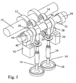
- Brennkraftmaschine mit einem Ventilmechanismus, welcher folgendes aufweist:ein Gaswechsel-Tellerventil (14),eine Nockenwelle (10), welche synchron mit der Motorkurbelwelle drehbar ist und einen Nocken (12) zum Betätigen des Ventils (14) aufweist,ein Ventilbetätigungsglied (20), welches das Ventil öffnend und schließend auf das Tellerventil (14) einwirkt, undeinen Zwischenkipphebel (30) mit einem von dem Nocken (12) beaufschlagten Folgeglied (34) und einer Konturenfläche (36), welche auf das Ventilbetätigungsglied (20) wirkt, um das Ventil (14) synchron mit der Drehung des Nockens (12) zu öffnen und zu schließen, wobei der Zwischenkipphebel (30) eine Schwenkachse hat, die zur Veränderung des Ventilhubes verstellbar ist,dadurch gekennzeichnet, daß
der Zwischenkipphebel (30) an einer Schwenklagerwelle (32) angebracht ist, welche derart bewegbar gelagert ist, daß der Ventilhub in Reaktion auf eine Drehbewegung der Schwenklagerwelle (32) um ihre eigene Achse verstellt wird, und
die Bewegung der Schwenklagerwelle (32) in eine Bahn gezwungen wird, die derart verläuft, daß, wenn sich das Folgeglied (34) am Grundkreis des Nockens (12) befindet, das Ventilbetätigungsglied (20) stationär bleibt, und zwischen der Konturenfläche (36) des Zwischenkipphebels (30) und dem Ventilbetätigungsglied (20) während der Bewegung der Schwenklagerwelle entlang dieser Bahn ein im wesentlichen konstantes Spiel erhalten wird. - Brennkraftmaschine nach Anspruch 1,
worin die Schwenklagerwelle (32) an dem Zwischenkipphebel (30) zwischen dem Nockenfolgeglied (34) und der Konturenfläche (36) angeordnet ist. - Brennkraftmaschine nach Anspruch 1 oder 2,
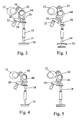
worin das Ventilbetätigungsglied als ein das Ventil betätigender Schlepphebel (20) ausgebildet ist, der an einem Ende schwenkbar gelagert ist und mit seinem anderen Ende das Ventil (14) betätigt, und der zwischen seinen Enden eine teilzylindrische Kontaktfläche oder ein Rollenfolgeglied (24) aufweist, die/das von der Konturenfläche (36) des Zwischenkipphebels (30) beaufschlagt wird. - Brennkraftmaschine nach Anspruch 3,
worin das Schwenkteil an besagtem einem Ende des Ventilbetätigungsschlepphebels (20) eine hydraulische Spielausgleichsvorrichtung (22) beinhaltet. - Brennkraftmaschine nach Anspruch 3 oder 4,
worin die Schwenklagerwelle (32) in einer Schwinge (38) drehbar gelagert ist, welche die Schwenklagerwelle (32) des Zwischenkipphebels (30) zwingt, in ihren Bewegungen einer Bogenbahn zu folgen, deren Zentrum in der Achse der Rolle (24) oder zylindrischen Kontaktfläche des Ventilbetätigungsschlepphebels (20) liegt. - Brennkraftmaschine nach Anspruch 5,
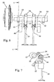
worin die Schwenklagerwelle (32) mit Spiel durch eine Bohrung in einer Exzenterhülse (44) tritt, die drehbar in einem stationären Lagerblock des Motors gelagert ist. - Brennkraftmaschine nach Anspruch 6,
worin die Exzenterhülse (44) mittels eines Stiftes (46) mit der Welle gekoppelt ist, welcher relativ zu wenigstens einer von Hülse (44) oder Welle (32) gleitend frei beweglich ist. - Brennkraftmaschine nach einem beliebigen der vorangehenden Ansprüche,
worin zwischen der Motorkurbelwelle und der Nockenwelle (10) ein Phasenverstellmechanismus (50) vorgesehen ist. - Brennkraftmaschine nach einem beliebigen der vorangehenden Ansprüche, mit zwei Ventilmechanismen zur Steuerung des Gasstromes in jeden und aus jedem Motorzylinder,
worin die Nockenprofile und/oder die Konturenflächen der Zwischenkipphebel, welche die beiden Ventile jedes Zylinders betätigen, jeweils von einander abweichende Geometrien haben, so daß die Ventilhubcharakteristik der beiden Ventile von einander unterschiedlich ist, wenn der Ventilhub verringert wird.
Applications Claiming Priority (3)
| Application Number | Priority Date | Filing Date | Title |
|---|---|---|---|
| GB0226842A GB2395229A (en) | 2002-11-16 | 2002-11-16 | Engine with variable valve lift and timing mechanism |
| GB0226842 | 2002-11-16 | ||
| PCT/GB2003/004864 WO2004046512A1 (en) | 2002-11-16 | 2003-11-12 | Engine with variable lift valve mechanism |
Publications (2)
| Publication Number | Publication Date |
|---|---|
| EP1561014A1 EP1561014A1 (de) | 2005-08-10 |
| EP1561014B1 true EP1561014B1 (de) | 2008-04-30 |
Family
ID=9948021
Family Applications (1)
| Application Number | Title | Priority Date | Filing Date |
|---|---|---|---|
| EP03775518A Expired - Lifetime EP1561014B1 (de) | 2002-11-16 | 2003-11-12 | Motor mit ventilmechanismus mit variablem hub |
Country Status (5)
| Country | Link |
|---|---|
| US (1) | US7117831B2 (de) |
| EP (1) | EP1561014B1 (de) |
| DE (1) | DE60320670T2 (de) |
| GB (1) | GB2395229A (de) |
| WO (1) | WO2004046512A1 (de) |
Families Citing this family (13)
| Publication number | Priority date | Publication date | Assignee | Title |
|---|---|---|---|---|
| EP1700014B1 (de) * | 2003-12-18 | 2007-05-23 | Toyota Jidosha Kabushiki Kaisha | Variabler ventilmechanismus |
| DE102004006187A1 (de) * | 2004-02-06 | 2005-08-25 | Volkswagen Ag | Ventiltrieb-Vorrichtung zur variablen Hubverstellung eines Gaswechselventils |
| DE102004006186A1 (de) * | 2004-02-06 | 2005-08-25 | Volkswagen Ag | Ventiltrieb-Vorrichtung zur variablen Hubverstellung eines Gaswechselventils |
| US7363893B2 (en) * | 2005-12-05 | 2008-04-29 | Delphi Technologies, Inc. | System for variable valvetrain actuation |
| US8225758B2 (en) * | 2008-05-22 | 2012-07-24 | Hyundai Motor Company | Continuously variable valve lift system for engines and controlling method thereof |
| WO2010096437A2 (en) | 2009-02-17 | 2010-08-26 | Cummins Inc. | Variable valve actuation apparatus, system, and method |
| KR101039897B1 (ko) * | 2009-08-13 | 2011-06-09 | 기아자동차주식회사 | 엔진의 연속 가변 밸브 리프트 장치 |
| US9133735B2 (en) | 2013-03-15 | 2015-09-15 | Kohler Co. | Variable valve timing apparatus and internal combustion engine incorporating the same |
| US9279350B2 (en) | 2014-05-27 | 2016-03-08 | Caterpillar Inc. | Intake valve closure control for dual-fuel engines |
| DE102015104633A1 (de) * | 2015-03-26 | 2016-09-29 | Pierburg Gmbh | Mechanisch steuerbarer Ventiltrieb sowie mechanisch steuerbare Ventiltriebanordnung |
| DE102016114664A1 (de) * | 2015-10-08 | 2017-04-13 | Toyota Jidosha Kabushiki Kaisha | Ventilbetätigungsvorrichtung für eine Brennkraftmaschine |
| EP3293374A1 (de) * | 2016-09-08 | 2018-03-14 | Pierburg GmbH | Mechanisch steuerbarer ventiltrieb |
| CN114763750A (zh) * | 2021-01-13 | 2022-07-19 | 舍弗勒技术股份两合公司 | 中间摇臂、可变气门升程系统和组装方法 |
Citations (1)
| Publication number | Priority date | Publication date | Assignee | Title |
|---|---|---|---|---|
| EP1039103A2 (de) * | 1999-03-26 | 2000-09-27 | Bayerische Motoren Werke Aktiengesellschaft | Vorrichtung zur Hubverstellung eines Gaswechselventils im Zylinderkopf einer Brennkraftmaschine |
Family Cites Families (6)
| Publication number | Priority date | Publication date | Assignee | Title |
|---|---|---|---|---|
| JPS55137305A (en) * | 1979-04-13 | 1980-10-27 | Nissan Motor Co Ltd | Valve lift for internal combustion engine |
| EP0717174A1 (de) * | 1994-12-12 | 1996-06-19 | Isuzu Motors Limited | Ventilantriebssystem für eine Brennkraftmaschine |
| DE19708484B4 (de) * | 1997-03-03 | 2006-07-13 | Bayerische Motoren Werke Ag | Vorrichtung zur Änderung des Ventilhubverlaufes eines Hubventils, insbesondere eines Gaswechselventils von Brennkraftmaschinen |
| FR2796982B1 (fr) * | 1999-07-28 | 2001-10-26 | Peugeot Citroen Automobiles Sa | Dispositif de commande d'une soupape et moteur a combustion interne muni de ce dispositif |
| GB2357131A (en) * | 1999-12-09 | 2001-06-13 | Mechadyne Internat Plc | Valve actuating mechanism |
| JP3799944B2 (ja) * | 2000-03-21 | 2006-07-19 | トヨタ自動車株式会社 | 内燃機関の可変動弁機構および吸気量制御装置 |
-
2002
- 2002-11-16 GB GB0226842A patent/GB2395229A/en not_active Withdrawn
-
2003
- 2003-11-12 DE DE60320670T patent/DE60320670T2/de not_active Expired - Lifetime
- 2003-11-12 EP EP03775518A patent/EP1561014B1/de not_active Expired - Lifetime
- 2003-11-12 US US10/534,995 patent/US7117831B2/en not_active Expired - Fee Related
- 2003-11-12 WO PCT/GB2003/004864 patent/WO2004046512A1/en not_active Ceased
Patent Citations (1)
| Publication number | Priority date | Publication date | Assignee | Title |
|---|---|---|---|---|
| EP1039103A2 (de) * | 1999-03-26 | 2000-09-27 | Bayerische Motoren Werke Aktiengesellschaft | Vorrichtung zur Hubverstellung eines Gaswechselventils im Zylinderkopf einer Brennkraftmaschine |
Also Published As
| Publication number | Publication date |
|---|---|
| US7117831B2 (en) | 2006-10-10 |
| GB0226842D0 (en) | 2002-12-24 |
| DE60320670D1 (de) | 2008-06-12 |
| DE60320670T2 (de) | 2009-06-10 |
| EP1561014A1 (de) | 2005-08-10 |
| GB2395229A (en) | 2004-05-19 |
| US20060011160A1 (en) | 2006-01-19 |
| WO2004046512A1 (en) | 2004-06-03 |
Similar Documents
| Publication | Publication Date | Title |
|---|---|---|
| EP1172528B1 (de) | Ventilsteuerungseinrichtung in einer Brennkraftmaschine | |
| US5592906A (en) | Method and device for variable valve control of an internal combustion engine | |
| EP1561014B1 (de) | Motor mit ventilmechanismus mit variablem hub | |
| US6311659B1 (en) | Desmodromic cam driven variable valve timing mechanism | |
| US4643141A (en) | Internal combustion engine valve lift and cam duration control system | |
| US6357405B1 (en) | Valve drive mechanism of four-stroke cycle engine | |
| CN100562648C (zh) | 可变气门操作装置 | |
| US6382149B1 (en) | Valve timing system for an internal combustion engine | |
| EP0601570B1 (de) | Ventiltrieb für Brennkraftmaschine | |
| US6378474B1 (en) | Variable value timing mechanism with crank drive | |
| US6968819B2 (en) | Variable valve actuating device | |
| US6491008B1 (en) | Variable valve timing adjustable roller rocker arm assembly | |
| US6382150B1 (en) | Desmodromic oscillating cam actuator with hydraulic lash adjuster | |
| WO2005052326A1 (en) | Engine valvegear | |
| US6481397B2 (en) | Variable valve drive system for an internal combustion engine | |
| JP3746786B2 (ja) | カム機構 | |
| US6360705B1 (en) | Mechanism for variable valve lift and cylinder deactivation | |
| EP1422388B1 (de) | Variable Ventilsteurungseinrichtung einer Brennkraftmaschine | |
| KR101221111B1 (ko) | 내연기관용 밸브 트레인 | |
| JP2001512546A (ja) | 弁用作動機構 | |
| EP0311272B1 (de) | Verstellungsvorrichtung für die Steuerzeiten und den Hub eines Ventils | |
| GB2323630A (en) | Variable timing valve operating mechanism, eg for i.c. engines | |
| EP3411568B1 (de) | Schaltbarer kiphebel mit einem variabler hebelverältnis | |
| CN121408050A (zh) | 一种可变气门驱动系统及车辆 | |
| GB2382859A (en) | Variable event valve timing mechanism |
Legal Events
| Date | Code | Title | Description |
|---|---|---|---|
| PUAI | Public reference made under article 153(3) epc to a published international application that has entered the european phase |
Free format text: ORIGINAL CODE: 0009012 |
|
| 17P | Request for examination filed |
Effective date: 20050412 |
|
| AK | Designated contracting states |
Kind code of ref document: A1 Designated state(s): AT BE BG CH CY CZ DE DK EE ES FI FR GB GR HU IE IT LI LU MC NL PT RO SE SI SK TR |
|
| RBV | Designated contracting states (corrected) |
Designated state(s): DE FR GB |
|
| 17Q | First examination report despatched |
Effective date: 20070308 |
|
| GRAP | Despatch of communication of intention to grant a patent |
Free format text: ORIGINAL CODE: EPIDOSNIGR1 |
|
| GRAS | Grant fee paid |
Free format text: ORIGINAL CODE: EPIDOSNIGR3 |
|
| GRAA | (expected) grant |
Free format text: ORIGINAL CODE: 0009210 |
|
| AK | Designated contracting states |
Kind code of ref document: B1 Designated state(s): DE FR GB |
|
| REG | Reference to a national code |
Ref country code: GB Ref legal event code: FG4D |
|
| REF | Corresponds to: |
Ref document number: 60320670 Country of ref document: DE Date of ref document: 20080612 Kind code of ref document: P |
|
| ET | Fr: translation filed | ||
| PLBE | No opposition filed within time limit |
Free format text: ORIGINAL CODE: 0009261 |
|
| STAA | Information on the status of an ep patent application or granted ep patent |
Free format text: STATUS: NO OPPOSITION FILED WITHIN TIME LIMIT |
|
| 26N | No opposition filed |
Effective date: 20090202 |
|
| REG | Reference to a national code |
Ref country code: GB Ref legal event code: 732E Free format text: REGISTERED BETWEEN 20130718 AND 20130724 |
|
| REG | Reference to a national code |
Ref country code: FR Ref legal event code: TP Owner name: MECHADYNE INTERNATIONAL LIMITED, GB Effective date: 20131015 Ref country code: FR Ref legal event code: CJ Effective date: 20131015 Ref country code: FR Ref legal event code: CD Owner name: MECHADYNE INTERNATIONAL LIMITED, GB Effective date: 20131015 |
|
| REG | Reference to a national code |
Ref country code: DE Ref legal event code: R082 Ref document number: 60320670 Country of ref document: DE Representative=s name: PATENTANWAELTE TER SMITTEN EBERLEIN RUETTEN PA, DE Ref country code: DE Ref legal event code: R082 Ref document number: 60320670 Country of ref document: DE Representative=s name: PATENTANWAELTE TER SMITTEN EBERLEIN-VAN HOOF R, DE |
|
| REG | Reference to a national code |
Ref country code: FR Ref legal event code: PLFP Year of fee payment: 13 |
|
| REG | Reference to a national code |
Ref country code: FR Ref legal event code: PLFP Year of fee payment: 14 |
|
| PGFP | Annual fee paid to national office [announced via postgrant information from national office to epo] |
Ref country code: GB Payment date: 20161124 Year of fee payment: 14 Ref country code: FR Payment date: 20161124 Year of fee payment: 14 Ref country code: DE Payment date: 20161125 Year of fee payment: 14 |
|
| REG | Reference to a national code |
Ref country code: DE Ref legal event code: R119 Ref document number: 60320670 Country of ref document: DE |
|
| GBPC | Gb: european patent ceased through non-payment of renewal fee |
Effective date: 20171112 |
|
| REG | Reference to a national code |
Ref country code: FR Ref legal event code: ST Effective date: 20180731 |
|
| PG25 | Lapsed in a contracting state [announced via postgrant information from national office to epo] |
Ref country code: FR Free format text: LAPSE BECAUSE OF NON-PAYMENT OF DUE FEES Effective date: 20171130 Ref country code: DE Free format text: LAPSE BECAUSE OF NON-PAYMENT OF DUE FEES Effective date: 20180602 |
|
| PG25 | Lapsed in a contracting state [announced via postgrant information from national office to epo] |
Ref country code: GB Free format text: LAPSE BECAUSE OF NON-PAYMENT OF DUE FEES Effective date: 20171112 |