EP1560944B1 - Apparatus for vacuum treating two dimensionally extended substrates and method for manufacturing such substrates - Google Patents
Apparatus for vacuum treating two dimensionally extended substrates and method for manufacturing such substrates Download PDFInfo
- Publication number
- EP1560944B1 EP1560944B1 EP03769143.3A EP03769143A EP1560944B1 EP 1560944 B1 EP1560944 B1 EP 1560944B1 EP 03769143 A EP03769143 A EP 03769143A EP 1560944 B1 EP1560944 B1 EP 1560944B1
- Authority
- EP
- European Patent Office
- Prior art keywords
- loadlock
- processing
- arrangement
- substrate
- substrates
- Prior art date
- Legal status (The legal status is an assumption and is not a legal conclusion. Google has not performed a legal analysis and makes no representation as to the accuracy of the status listed.)
- Expired - Lifetime
Links
Images





Classifications
-
- B—PERFORMING OPERATIONS; TRANSPORTING
- B65—CONVEYING; PACKING; STORING; HANDLING THIN OR FILAMENTARY MATERIAL
- B65G—TRANSPORT OR STORAGE DEVICES, e.g. CONVEYORS FOR LOADING OR TIPPING, SHOP CONVEYOR SYSTEMS OR PNEUMATIC TUBE CONVEYORS
- B65G49/00—Conveying systems characterised by their application for specified purposes not otherwise provided for
- B65G49/05—Conveying systems characterised by their application for specified purposes not otherwise provided for for fragile or damageable materials or articles
- B65G49/07—Conveying systems characterised by their application for specified purposes not otherwise provided for for fragile or damageable materials or articles for semiconductor wafers Not used, see H10P72/00
-
- H—ELECTRICITY
- H10—SEMICONDUCTOR DEVICES; ELECTRIC SOLID-STATE DEVICES NOT OTHERWISE PROVIDED FOR
- H10P—GENERIC PROCESSES OR APPARATUS FOR THE MANUFACTURE OR TREATMENT OF DEVICES COVERED BY CLASS H10
- H10P72/00—Handling or holding of wafers, substrates or devices during manufacture or treatment thereof
- H10P72/04—Apparatus for manufacture or treatment
- H10P72/0451—Apparatus for manufacturing or treating in a plurality of work-stations
- H10P72/0452—Apparatus for manufacturing or treating in a plurality of work-stations characterised by the layout of the process chambers
- H10P72/0458—Apparatus for manufacturing or treating in a plurality of work-stations characterised by the layout of the process chambers vertical arrangement
-
- C—CHEMISTRY; METALLURGY
- C23—COATING METALLIC MATERIAL; COATING MATERIAL WITH METALLIC MATERIAL; CHEMICAL SURFACE TREATMENT; DIFFUSION TREATMENT OF METALLIC MATERIAL; COATING BY VACUUM EVAPORATION, BY SPUTTERING, BY ION IMPLANTATION OR BY CHEMICAL VAPOUR DEPOSITION, IN GENERAL; INHIBITING CORROSION OF METALLIC MATERIAL OR INCRUSTATION IN GENERAL
- C23C—COATING METALLIC MATERIAL; COATING MATERIAL WITH METALLIC MATERIAL; SURFACE TREATMENT OF METALLIC MATERIAL BY DIFFUSION INTO THE SURFACE, BY CHEMICAL CONVERSION OR SUBSTITUTION; COATING BY VACUUM EVAPORATION, BY SPUTTERING, BY ION IMPLANTATION OR BY CHEMICAL VAPOUR DEPOSITION, IN GENERAL
- C23C14/00—Coating by vacuum evaporation, by sputtering or by ion implantation of the coating forming material
- C23C14/22—Coating by vacuum evaporation, by sputtering or by ion implantation of the coating forming material characterised by the process of coating
- C23C14/56—Apparatus specially adapted for continuous coating; Arrangements for maintaining the vacuum, e.g. vacuum locks
-
- C—CHEMISTRY; METALLURGY
- C23—COATING METALLIC MATERIAL; COATING MATERIAL WITH METALLIC MATERIAL; CHEMICAL SURFACE TREATMENT; DIFFUSION TREATMENT OF METALLIC MATERIAL; COATING BY VACUUM EVAPORATION, BY SPUTTERING, BY ION IMPLANTATION OR BY CHEMICAL VAPOUR DEPOSITION, IN GENERAL; INHIBITING CORROSION OF METALLIC MATERIAL OR INCRUSTATION IN GENERAL
- C23C—COATING METALLIC MATERIAL; COATING MATERIAL WITH METALLIC MATERIAL; SURFACE TREATMENT OF METALLIC MATERIAL BY DIFFUSION INTO THE SURFACE, BY CHEMICAL CONVERSION OR SUBSTITUTION; COATING BY VACUUM EVAPORATION, BY SPUTTERING, BY ION IMPLANTATION OR BY CHEMICAL VAPOUR DEPOSITION, IN GENERAL
- C23C14/00—Coating by vacuum evaporation, by sputtering or by ion implantation of the coating forming material
- C23C14/22—Coating by vacuum evaporation, by sputtering or by ion implantation of the coating forming material characterised by the process of coating
- C23C14/56—Apparatus specially adapted for continuous coating; Arrangements for maintaining the vacuum, e.g. vacuum locks
- C23C14/564—Means for minimising impurities in the coating chamber such as dust, moisture, residual gases
- C23C14/566—Means for minimising impurities in the coating chamber such as dust, moisture, residual gases using a load-lock chamber
-
- C—CHEMISTRY; METALLURGY
- C23—COATING METALLIC MATERIAL; COATING MATERIAL WITH METALLIC MATERIAL; CHEMICAL SURFACE TREATMENT; DIFFUSION TREATMENT OF METALLIC MATERIAL; COATING BY VACUUM EVAPORATION, BY SPUTTERING, BY ION IMPLANTATION OR BY CHEMICAL VAPOUR DEPOSITION, IN GENERAL; INHIBITING CORROSION OF METALLIC MATERIAL OR INCRUSTATION IN GENERAL
- C23C—COATING METALLIC MATERIAL; COATING MATERIAL WITH METALLIC MATERIAL; SURFACE TREATMENT OF METALLIC MATERIAL BY DIFFUSION INTO THE SURFACE, BY CHEMICAL CONVERSION OR SUBSTITUTION; COATING BY VACUUM EVAPORATION, BY SPUTTERING, BY ION IMPLANTATION OR BY CHEMICAL VAPOUR DEPOSITION, IN GENERAL
- C23C14/00—Coating by vacuum evaporation, by sputtering or by ion implantation of the coating forming material
- C23C14/22—Coating by vacuum evaporation, by sputtering or by ion implantation of the coating forming material characterised by the process of coating
- C23C14/56—Apparatus specially adapted for continuous coating; Arrangements for maintaining the vacuum, e.g. vacuum locks
- C23C14/568—Transferring the substrates through a series of coating stations
-
- C—CHEMISTRY; METALLURGY
- C23—COATING METALLIC MATERIAL; COATING MATERIAL WITH METALLIC MATERIAL; CHEMICAL SURFACE TREATMENT; DIFFUSION TREATMENT OF METALLIC MATERIAL; COATING BY VACUUM EVAPORATION, BY SPUTTERING, BY ION IMPLANTATION OR BY CHEMICAL VAPOUR DEPOSITION, IN GENERAL; INHIBITING CORROSION OF METALLIC MATERIAL OR INCRUSTATION IN GENERAL
- C23C—COATING METALLIC MATERIAL; COATING MATERIAL WITH METALLIC MATERIAL; SURFACE TREATMENT OF METALLIC MATERIAL BY DIFFUSION INTO THE SURFACE, BY CHEMICAL CONVERSION OR SUBSTITUTION; COATING BY VACUUM EVAPORATION, BY SPUTTERING, BY ION IMPLANTATION OR BY CHEMICAL VAPOUR DEPOSITION, IN GENERAL
- C23C16/00—Chemical coating by decomposition of gaseous compounds, without leaving reaction products of surface material in the coating, i.e. chemical vapour deposition [CVD] processes
- C23C16/44—Chemical coating by decomposition of gaseous compounds, without leaving reaction products of surface material in the coating, i.e. chemical vapour deposition [CVD] processes characterised by the method of coating
- C23C16/54—Apparatus specially adapted for continuous coating
-
- F—MECHANICAL ENGINEERING; LIGHTING; HEATING; WEAPONS; BLASTING
- F27—FURNACES; KILNS; OVENS; RETORTS
- F27B—FURNACES, KILNS, OVENS OR RETORTS IN GENERAL; OPEN SINTERING OR LIKE APPARATUS
- F27B17/00—Furnaces of a kind not covered by any of groups F27B1/00 - F27B15/00
- F27B17/0016—Chamber type furnaces
- F27B17/0025—Chamber type furnaces specially adapted for treating semiconductor wafers
-
- F—MECHANICAL ENGINEERING; LIGHTING; HEATING; WEAPONS; BLASTING
- F27—FURNACES; KILNS; OVENS; RETORTS
- F27B—FURNACES, KILNS, OVENS OR RETORTS IN GENERAL; OPEN SINTERING OR LIKE APPARATUS
- F27B5/00—Muffle furnaces; Retort furnaces; Other furnaces in which the charge is held completely isolated
- F27B5/04—Muffle furnaces; Retort furnaces; Other furnaces in which the charge is held completely isolated adapted for treating the charge in vacuum or special atmosphere
-
- F—MECHANICAL ENGINEERING; LIGHTING; HEATING; WEAPONS; BLASTING
- F27—FURNACES; KILNS; OVENS; RETORTS
- F27B—FURNACES, KILNS, OVENS OR RETORTS IN GENERAL; OPEN SINTERING OR LIKE APPARATUS
- F27B5/00—Muffle furnaces; Retort furnaces; Other furnaces in which the charge is held completely isolated
- F27B5/06—Details, accessories or equipment specially adapted for furnaces of these types
- F27B5/12—Arrangement of devices for charging
-
- F—MECHANICAL ENGINEERING; LIGHTING; HEATING; WEAPONS; BLASTING
- F27—FURNACES; KILNS; OVENS; RETORTS
- F27D—DETAILS OR ACCESSORIES OF FURNACES, KILNS, OVENS OR RETORTS, IN SO FAR AS THEY ARE OF KINDS OCCURRING IN MORE THAN ONE KIND OF FURNACE
- F27D3/00—Charging; Discharging; Manipulation of charge
- F27D3/0084—Charging; Manipulation of SC or SC wafers
-
- F—MECHANICAL ENGINEERING; LIGHTING; HEATING; WEAPONS; BLASTING
- F27—FURNACES; KILNS; OVENS; RETORTS
- F27D—DETAILS OR ACCESSORIES OF FURNACES, KILNS, OVENS OR RETORTS, IN SO FAR AS THEY ARE OF KINDS OCCURRING IN MORE THAN ONE KIND OF FURNACE
- F27D3/00—Charging; Discharging; Manipulation of charge
- F27D3/06—Charging or discharging machines on travelling carriages
-
- H—ELECTRICITY
- H10—SEMICONDUCTOR DEVICES; ELECTRIC SOLID-STATE DEVICES NOT OTHERWISE PROVIDED FOR
- H10P—GENERIC PROCESSES OR APPARATUS FOR THE MANUFACTURE OR TREATMENT OF DEVICES COVERED BY CLASS H10
- H10P72/00—Handling or holding of wafers, substrates or devices during manufacture or treatment thereof
- H10P72/04—Apparatus for manufacture or treatment
- H10P72/0402—Apparatus for fluid treatment
-
- H—ELECTRICITY
- H10—SEMICONDUCTOR DEVICES; ELECTRIC SOLID-STATE DEVICES NOT OTHERWISE PROVIDED FOR
- H10P—GENERIC PROCESSES OR APPARATUS FOR THE MANUFACTURE OR TREATMENT OF DEVICES COVERED BY CLASS H10
- H10P72/00—Handling or holding of wafers, substrates or devices during manufacture or treatment thereof
- H10P72/04—Apparatus for manufacture or treatment
- H10P72/0451—Apparatus for manufacturing or treating in a plurality of work-stations
- H10P72/0466—Apparatus for manufacturing or treating in a plurality of work-stations characterised by the construction of the load-lock chamber
-
- H—ELECTRICITY
- H10—SEMICONDUCTOR DEVICES; ELECTRIC SOLID-STATE DEVICES NOT OTHERWISE PROVIDED FOR
- H10P—GENERIC PROCESSES OR APPARATUS FOR THE MANUFACTURE OR TREATMENT OF DEVICES COVERED BY CLASS H10
- H10P72/00—Handling or holding of wafers, substrates or devices during manufacture or treatment thereof
- H10P72/04—Apparatus for manufacture or treatment
- H10P72/0478—Apparatus for manufacture or treatment the substrates being processed being not semiconductor wafers, e.g. leadframes or chips
-
- H—ELECTRICITY
- H10—SEMICONDUCTOR DEVICES; ELECTRIC SOLID-STATE DEVICES NOT OTHERWISE PROVIDED FOR
- H10P—GENERIC PROCESSES OR APPARATUS FOR THE MANUFACTURE OR TREATMENT OF DEVICES COVERED BY CLASS H10
- H10P72/00—Handling or holding of wafers, substrates or devices during manufacture or treatment thereof
- H10P72/30—Handling or holding of wafers, substrates or devices during manufacture or treatment thereof for conveying, e.g. between different workstations
- H10P72/33—Handling or holding of wafers, substrates or devices during manufacture or treatment thereof for conveying, e.g. between different workstations into and out of processing chamber
- H10P72/3302—Mechanical parts of transfer devices
-
- H—ELECTRICITY
- H10—SEMICONDUCTOR DEVICES; ELECTRIC SOLID-STATE DEVICES NOT OTHERWISE PROVIDED FOR
- H10P—GENERIC PROCESSES OR APPARATUS FOR THE MANUFACTURE OR TREATMENT OF DEVICES COVERED BY CLASS H10
- H10P72/00—Handling or holding of wafers, substrates or devices during manufacture or treatment thereof
- H10P72/30—Handling or holding of wafers, substrates or devices during manufacture or treatment thereof for conveying, e.g. between different workstations
- H10P72/33—Handling or holding of wafers, substrates or devices during manufacture or treatment thereof for conveying, e.g. between different workstations into and out of processing chamber
- H10P72/3304—Handling or holding of wafers, substrates or devices during manufacture or treatment thereof for conveying, e.g. between different workstations into and out of processing chamber characterised by movements or sequence of movements of transfer devices
-
- H—ELECTRICITY
- H10—SEMICONDUCTOR DEVICES; ELECTRIC SOLID-STATE DEVICES NOT OTHERWISE PROVIDED FOR
- H10P—GENERIC PROCESSES OR APPARATUS FOR THE MANUFACTURE OR TREATMENT OF DEVICES COVERED BY CLASS H10
- H10P72/00—Handling or holding of wafers, substrates or devices during manufacture or treatment thereof
- H10P72/30—Handling or holding of wafers, substrates or devices during manufacture or treatment thereof for conveying, e.g. between different workstations
- H10P72/33—Handling or holding of wafers, substrates or devices during manufacture or treatment thereof for conveying, e.g. between different workstations into and out of processing chamber
- H10P72/3306—Horizontal transfer of a single workpiece
-
- H—ELECTRICITY
- H10—SEMICONDUCTOR DEVICES; ELECTRIC SOLID-STATE DEVICES NOT OTHERWISE PROVIDED FOR
- H10P—GENERIC PROCESSES OR APPARATUS FOR THE MANUFACTURE OR TREATMENT OF DEVICES COVERED BY CLASS H10
- H10P72/00—Handling or holding of wafers, substrates or devices during manufacture or treatment thereof
- H10P72/30—Handling or holding of wafers, substrates or devices during manufacture or treatment thereof for conveying, e.g. between different workstations
- H10P72/33—Handling or holding of wafers, substrates or devices during manufacture or treatment thereof for conveying, e.g. between different workstations into and out of processing chamber
- H10P72/3311—Horizontal transfer of a batch of workpieces
-
- H—ELECTRICITY
- H10—SEMICONDUCTOR DEVICES; ELECTRIC SOLID-STATE DEVICES NOT OTHERWISE PROVIDED FOR
- H10P—GENERIC PROCESSES OR APPARATUS FOR THE MANUFACTURE OR TREATMENT OF DEVICES COVERED BY CLASS H10
- H10P72/00—Handling or holding of wafers, substrates or devices during manufacture or treatment thereof
- H10P72/30—Handling or holding of wafers, substrates or devices during manufacture or treatment thereof for conveying, e.g. between different workstations
- H10P72/34—Handling or holding of wafers, substrates or devices during manufacture or treatment thereof for conveying, e.g. between different workstations the wafers being stored in a carrier, involving loading and unloading
- H10P72/3402—Mechanical parts of transfer devices
-
- H—ELECTRICITY
- H10—SEMICONDUCTOR DEVICES; ELECTRIC SOLID-STATE DEVICES NOT OTHERWISE PROVIDED FOR
- H10P—GENERIC PROCESSES OR APPARATUS FOR THE MANUFACTURE OR TREATMENT OF DEVICES COVERED BY CLASS H10
- H10P72/00—Handling or holding of wafers, substrates or devices during manufacture or treatment thereof
- H10P72/30—Handling or holding of wafers, substrates or devices during manufacture or treatment thereof for conveying, e.g. between different workstations
- H10P72/34—Handling or holding of wafers, substrates or devices during manufacture or treatment thereof for conveying, e.g. between different workstations the wafers being stored in a carrier, involving loading and unloading
- H10P72/3406—Handling or holding of wafers, substrates or devices during manufacture or treatment thereof for conveying, e.g. between different workstations the wafers being stored in a carrier, involving loading and unloading involving removal of lid, door or cover
-
- H—ELECTRICITY
- H10—SEMICONDUCTOR DEVICES; ELECTRIC SOLID-STATE DEVICES NOT OTHERWISE PROVIDED FOR
- H10P—GENERIC PROCESSES OR APPARATUS FOR THE MANUFACTURE OR TREATMENT OF DEVICES COVERED BY CLASS H10
- H10P72/00—Handling or holding of wafers, substrates or devices during manufacture or treatment thereof
- H10P72/30—Handling or holding of wafers, substrates or devices during manufacture or treatment thereof for conveying, e.g. between different workstations
- H10P72/34—Handling or holding of wafers, substrates or devices during manufacture or treatment thereof for conveying, e.g. between different workstations the wafers being stored in a carrier, involving loading and unloading
- H10P72/3411—Handling or holding of wafers, substrates or devices during manufacture or treatment thereof for conveying, e.g. between different workstations the wafers being stored in a carrier, involving loading and unloading involving loading and unloading of wafers
- H10P72/3412—Batch transfer of wafers
-
- H—ELECTRICITY
- H10—SEMICONDUCTOR DEVICES; ELECTRIC SOLID-STATE DEVICES NOT OTHERWISE PROVIDED FOR
- H10P—GENERIC PROCESSES OR APPARATUS FOR THE MANUFACTURE OR TREATMENT OF DEVICES COVERED BY CLASS H10
- H10P72/00—Handling or holding of wafers, substrates or devices during manufacture or treatment thereof
- H10P72/50—Handling or holding of wafers, substrates or devices during manufacture or treatment thereof for positioning, orientation or alignment
-
- F—MECHANICAL ENGINEERING; LIGHTING; HEATING; WEAPONS; BLASTING
- F27—FURNACES; KILNS; OVENS; RETORTS
- F27D—DETAILS OR ACCESSORIES OF FURNACES, KILNS, OVENS OR RETORTS, IN SO FAR AS THEY ARE OF KINDS OCCURRING IN MORE THAN ONE KIND OF FURNACE
- F27D3/00—Charging; Discharging; Manipulation of charge
- F27D2003/0034—Means for moving, conveying, transporting the charge in the furnace or in the charging facilities
- F27D2003/0065—Lifts, e.g. containing the bucket elevators
-
- Y—GENERAL TAGGING OF NEW TECHNOLOGICAL DEVELOPMENTS; GENERAL TAGGING OF CROSS-SECTIONAL TECHNOLOGIES SPANNING OVER SEVERAL SECTIONS OF THE IPC; TECHNICAL SUBJECTS COVERED BY FORMER USPC CROSS-REFERENCE ART COLLECTIONS [XRACs] AND DIGESTS
- Y10—TECHNICAL SUBJECTS COVERED BY FORMER USPC
- Y10S—TECHNICAL SUBJECTS COVERED BY FORMER USPC CROSS-REFERENCE ART COLLECTIONS [XRACs] AND DIGESTS
- Y10S414/00—Material or article handling
- Y10S414/135—Associated with semiconductor wafer handling
- Y10S414/139—Associated with semiconductor wafer handling including wafer charging or discharging means for vacuum chamber
Definitions
- the present invention is most generically directed on vacuum treating of extended relatively thin substrates as especially substrates for manufacturing solar panels, TFT display panels, or plasma display panels.
- large and thin substrates as e.g. of glass have to be vacuum process treated thereby including deposition of semi-conductive layers.
- the apparatuses for industrially and automatically treating such substrates become larger and larger. Because the substrates are maintained during transporting and vacuum processing in horizontal orientation the apparatus for such substrate processing especially becomes large with respect to their footprint surface. Because such treating facilities or apparatus are installed in clean room ambient, this leads to an increased volume thereof which significantly raises manufacturing costs.
- handling robots become larger especially under consideration of their footprint surfaces and must be tailored to safely transport such substrates between loadlocks and processing stations in the vacuum treatment facilities.
- the known apparatus is principally conceived with loadlock-and processing chambers vertically stacked one upon the other with a transport chamber performing substrate handling between a loadlock chamber and the processing chambers.
- the known apparatus provides for two vertical towers, one thereof consisting of an input/output loadlock chamber and processing chambers arranged beneath the loadlock chamber, the other tower consisting only of processing chambers.
- the two towers are arranged with workpiece handling openings facing each other on opposite sides of a central transport arrangement which has a lift type transport robot serving the openings of the two towers.
- the loadlock- and processing towers thereby defines for respective self-contained, all-in-one substrate processing modules.
- At least two loadlock- and processing towers each formed by one loadlock arrangement and one processing arrangement are provided.
- One single transport arrangement is used to serve the two or more than two loadlock- and processing towers.
- Each of these towers thereby defines in a self-contained all-in-one desired multi-step substrate process inclusive input and output loadlocking the substrates. Thereby complete parallel, multi-step processing ability is realised of equal or different multi-step processes.
- a processing chamber or compartment which is used for processing substrates from both or from a number of loadlock- and processing towers as provided.
- a commonly used compartment or chamber may for instance be a intermediate storage chamber for substrates to be longterm equalized with respect to their temperature after having been treated and before being despatched by the respective loadlock to ambient.
- Such a commonly used treatment compartment or chamber may be provided for instance beneath both towers as provided, thereby exploiting for substrate intermediate storage the overall footprint surface of the apparatus.
- the apparatus according to the present invention may be conceived to provide for single substrate or for substrate batch processing or, in a mixed mode, for single substrate and substrate batch processing along the at least one loadlock and processing tower as provided.
- the transport robot comprises at least one substantially horizontal substrate support for at least one substrate whereby the substrate support is driven and controllably movable in a vertical direction to bring the substrate in alignment with an opening to one of the addressed towers and which is further driven and controllably movable in horizontal direction to bring the substrate support into and out of one of the towers thereby leaving such substrate in the tower for processing or loadlocking or removing such substrate from processing or from loadlocking.
- the substrate support is additionally rotatable about a vertical axis in a controllably driven manner. Nevertheless, if the substrate support is rotatable at all the rotational movement is preferably limited to at most 180° thereby even more preferred, to at most 45°. Nevertheless, in the today's most preferred embodiment the substrate support is exclusively moveable in a controllably driven manner linearly horizontally and vertically.
- At least one of the processing arrangements comprises at least one substrate batch processing module wherein simultaneously more than one substrate are loaded, processed simultaneously and simultaneously removed.
- a further preferred embodiment, which may also be combined with substrate batch handling and processing the at least one processing arrangement, comprises at least one single substrate processing module.
- At least one loadlock arrangement comprises an input/output loadlock arrangement whereat both loadlocking of at least one substrate from surrounding atmosphere towards the transport chamber as well as from the transport chamber towards surrounding atmosphere are performed.
- such input/output loadlock arrangement comprises at least one single substrate input loadlock chamber.
- said imput/output loadlock arrangement comprises at least one single substrate output loadlock chamber.
- Still a further mode of the addressed input/output loadlock arrangement comprises at least one of a substrate batch input loadlock chamber, of a substrate batch output loadlock chamber and of an input/output substrate batch loadlock chamber.
- a further mode comprises one of the loadlock- and processing towers comprising one of an input and of output loadlock arrangement.
- a further preferred mode has exclusively two of the loadlock- and processing towers which are arranged opposite one another i.e. on opposite sides of the transport vacuum chamber and thus facing each other with their respective openings via the transport chamber. This is an I-type concept.
- the apparatus has still exclusively two loadlock- and processing towers which are arranged one aside the other and on one side of the vacuum transport chamber thereby concomitantly defining with the vacuum transport chamber a U-type footprint surface.
- the apparatus has still exclusively two loadlock- and processing towers which concomitantly define for a Y-type footprint surface together with the transport chamber.
- the apparatus has a substrate handling and processing ability for substrates which have an extent of at least 1m 2 , preferably of at least 2m 2 and especially preferred even of at least 4m 2 .
- the loadlock arrangement comprises at least one of a heating and of cooling arrangement for at least one substrate.
- the vacuum treated substrates may be one of solar panel substrates, of TFT display panel substrates and of plasma display panels.
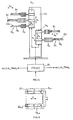
- Fig. 1 there is shown schematically the side view of a loadlock- and processing tower LLPT 1 as one essential part as used in the frame of the present invention.
- the LLPT is a vertical tower which comprises a loadlock arrangement LLA and a processing arrangement PMA.
- the loadlock arrangement LLA may comprise at least one single substrate input/output loadlock chamber, at least one single substrate input loadlock chamber, at least one single substrate output loadlock chamber, at least one substrate batch input/output load lock chamber, at least one substrate batch input loadlock chamber, at least one substrate batch output loadlock chamber.
- the loadlock arrangement LLA of the LLPT 1 comprises at least one loadlock chamber.
- the loadlock arrangement LLA as of Fig. 1 communicates on the one hand with an outside atmosphere AT as with ambient atmosphere, and on the other hand with a vacuum atmosphere V in a transport arrangement TA 2.
- the double line/double direction arrows in Fig. 1 indicate most generically two-directional handling of one or more than one substrate between the atmosphere AT, the interior of the loadlock arrangement LLA and the transport arrangement TA 2.
- a LLPT 1 may have a loadlock arrangement LLA which has only an input load lock arrangement or only an output load lock arrangement, i.e. a loadlock arrangement for transmitting substrates from the atmosphere AT towards the transport arrangement TA 2, or for transmitting substrates from the transport arrangement TA 2 towards the atmosphere AT.
- handling of the one or more than one substrate between the loadlock arrangement LLA and atmosphere AT as well as the transport arrangement TA 2 is performed via respective openings O which are sealably and controllably closable by respective loadlock valves, as schematically shown in Fig. 1 by the controllable, sealably closable openings O s .
- the loadlock- and processing tower LLPT 1 further comprises a process module arrangement PMA which comprises one or preferably more than one processing chambers.
- processing chambers may thereby be single substrate processing chambers or substrate batch processing chambers.
- the respective substrates or substrate batches are processed by a vacuum treatment process, thereby e.g. by a CVD, PECVD, PVD process, or by heating, cooling, etc. With respect to substrate heating and/or cooling, nevertheless such processing may be performed exclusively or additionally within the LLA.
- the PMA and the transport arrangement TA are in two-directional substrate handling communication. Further and dependent on the type of processes performed in the PMA and their specific requirements with respect to cleanliness, such bidirectional substrate handling between PMA and TA occurs via openings O which are, as also schematically shown in Fig. 1 permanent open, O P , controllably closable but not sealingly closable, O ps , or controllably and sealingly closable, O s .
- the important feature of the loadlock- and processing tower LLPT 1 is that, vertically stacked, there is provided a loadlock arrangement LLA and a processing module arrangement PMA.
- Figs. 2 to 7 show in representations in analogy to that of Fig. 1 , different preferred forms of realising the LLPT 1.
- the LLPT 1 comprises a number, for instance and as shown, three single substrate input/output loadlock stations LL io forming the LLA according to Fig. 1 .
- the PMA in the embodiment of Fig. 2 consists of a further number, for instance again three single substrate processing chambers PM 1 to PM 3 .
- the structure of LLA is the same as in the embodiment of Fig. 2 .
- the PMA consists of a single substrate batch processing module BPM.
- the process module arrangement PMA is in fact equal to that as shown in Fig. 2 .
- the loadlock arrangement LLA consists here of a first number of input single substrate loadlock modules LL i and of a second number as of output loadlock modules LL o .
- the load lock arrangement LLA is conceived equally to the LLA of the embodiment of Fig. 4
- the processing module arrangement PMA consists of a batch processing module BPM as of the embodiment of Fig. 3 .
- the embodiment of the LLPT 1 as of Fig. 6 consists of a process module arrangement PMA realised e.g. as shown in one of the embodiments of Figs. 2 to 5 .
- the loadlock arrangement LLA consists of a substrate batch input/output load lock chamber BLL io .
- the load lock arrangement LLA consists of a substrate batch input load lock module BLL i and of a substrate batch output load lock module BLL o .
- the present invention is especially directed on vacuum treating large two-dimensionally extended substrates, e.g. with sizes of at least 1m 2 , preferably of at least 2m 2 , and even of 4m 2 and more.
- Fig. 8 there is schematically shown a top view upon a LLPT 1 as of Figs. 1 to 7 with a large surface substrate 3 positioned therein.
- a LLPT 1 as of Figs. 1 to 7 with a large surface substrate 3 positioned therein.
- Such positioning is preferably applied in the loadlock arrangement LLA as well as in the process module arrangement PMA.
- Fig. 9 schematically shows in a side view a part of a bottom wall 5, be it of a module of the load lock arrangement LLA, be it of a module of the processing module arrangement PMA.
- a large substrate 3 is deposited on a positioning arrangement which comprises, as schematically shown in Fig. 9 , e.g. a member of distinct deposition pins 7 whereupon, the thin and large extent substrate 3 resides.
- LLPT 1 per se, which means that any kind of its detailed structure, as was exemplified with respect to the Figs. 1 to 9 , may be applied. Only if specific measures should be or preferably are taken in consideration such LLPT in a specific embodiment to be described, then such embodiment of a LLPT will specifically be addressed.
- FIG. 10 there is shown schematically a side view of an embodiment of an apparatus for manufacturing vacuum treated, substantially plane substrates.
- This embodiment essentially consists of one single LLPT 1.
- the LLPT 1 communicates by respective loadlock- and process module-openings, which are vertically aligned, with a transport arrangement TA 2 which latter performs handling of the substrates into and from the loadlock arrangement LLA as well as into and from the process module arrangement PMA.
- the transport arrangement 2 comprises a transport robot 9 which performs substrate transport according to h horizontally into and from respective modules of the loadlock arrangement LLA and of the process module arrangement PMA and further performs vertical transport v from a position aligned with at least one respective first opening towards alignment with at least one respective second opening of the PMA and LLA.
- Fig. 11 schematically shows the apparatus as of Fig. 10 in top view.
- the apparatus comprises one transport arrangement TA 2 which serves one single LLPT 1 which latter comprises a loadlock arrangement LLA as well as process module arrangement PMA.
- the loadlock arrangement LLA comprises input/output loadlocking ability as schematically shown in Fig. 10 by the double arrow i/o.
- the LLPT 1 defines for all loadlocking and processing which is necessary for a predetermined multiprocessing step treatment of at least one substrate.
- the transport arrangement TA 2 is provided to serve the substrate between respective openings at the LLPT 1.
- the transport arrangement TA 2 needs only perform by its robotic transporting member 9 horizontal - h - and vertical - v - transport movements.
- the LLPT 1 Whenever a different processing with different processing steps is to be performed on substrates, only the LLPT 1 must be exchanged. Due to the fact that all the modules or stations which are necessary for an intended substrate processing are stapled vertically one upon the other to result in the addressed LLPT 1, the footprint of all the modules necessary for such processing is a minimum. Additionally, the footprint of the transport arrangement is minimum as necessary to serve horizontally the respective modules of the LLA and PMA. In opposition to the teaching of the US 5 275 709 the apparatus as of Fig. 10 and 11 in fact provides for a tower of modules which provide for all processing steps desired inclusive inputting and outputting the substrates to and from processing stations.
- a first LLPT 1a and a second LLPT 1b are both in communication with a common transport arrangement TA.
- the conceptions of the LLA a of the first LLPT 1a as well as of PMA a of that first LLPT 1a are selected to perform a first well-defined processing sequence with different processing steps upon substrates 3a.
- each tower 1a and 1b per se provides for the complete ability to perform inputting/outputting of respective substrates to the respective vacuum treatment processes as well as the complete set of processing modules to perform the requested tower specific processing.
- the transport arrangement 2ab has the ability to perform horizontal and vertical substrate transport with respect to the first LLPT 1a and with respect to the second LLPT 1b completely independently.
- a robot 9ab is controlled to perform horizontal transportation h a with respect to tower 1a independently from such horizontal transportation h b with respect to the second tower 1b and in analogy to perform vertical v a transportation of substrates processed in tower 1a independently from such transport v b with respect to the second tower 1b.
- Fig. 14 there is schematically shown a robot 11 which may be applied within the vacuum chamber of the transport arrangement TA as of figure 12 and 13 .
- Fig. 14 there is provided within the vacuum chamber of the transport arrangements (not shown) a stationary central support post 13.
- a first sliding arrangement 14 a which is vertically slideable - va - in controlled driven manner.
- a number of single substrate supporting member 15 a mounted to sliding arrangement 14 a there is provided a number of single substrate supporting member 15 a , as shown e.g. three. They project horizontally and are vertically mounted distant form each other and, in one preferred embodiment, with a controllably variable pitch distance p a .
- the pitch distance p a in this preferred embodiment may be controllably varied, e.g. to accommodate for substrate handling openings at the LLA and/or PMA with different vertical pitch distances.
- Each of the supporting members 15 a may be expanded and retracted horizontally - h -, driven by telescopic drives, as shown within encapsulations 17 a .
- the supporting members 15 a have supports with supporting pins 20 whereupon the substrates 3a to be processed in LLPT 1a are disposed during horizontal and vertical transport.
- a second sliding arrangement 14 b opposite sliding arrangement 14 a along post 13, which is construed with supporting members 15 b , supports 19 b supporting pins 20 b , encapsulates 17 b very much like the arrangement mounted on slide 14 a whereby, as shown, the number of supporting members 15 b which do handle substrates 3b with respect to LLPT 1b as of figure 12 or 13 needs not to be equal with the number of members 15 a for serving substrate 3a to be processed by a LLPT 1a.
- the horizontally movable supports 9a and 9b are construed in a forklike manner as shown in Fig. 15 .
- Fig. 15 shows a respective substrate 3a,b residing on the support 19 a,b and being thereby deposited on support pins 21 in a LLA or PMA.
- an apparatus with two distinct loadlock- and processing towers LLPT 1a and 1b which each provide for the complete set of modules to perform substrate processing inclusive feeding such substrate from surrounding atmosphere AT to the vacuum processing and from vacuum processing back to surrounding atmosphere.
- the robot 9ab within the transport arrangements TA 2ab needs not perform any rotational movement.
- Substrate transport is realised merely by horizontal - h - and vertical - v - substrate movement.
- a controlling unit 21 is provided for controlling the horizontal transport movements h a,b , the vertical transport movements v a,b with respect to their extent, timing of respective horizontal and vertical transport cycles as well as, if necessary, pitch distance pa of the respective support arrangements.
- a control unit 21 is preferably realised as a free programmable unit so that in dependency of an intended processing especially timing of the transport cycles may flexibly be adapted.
- Such a controlling unit 21 preferably also controls processing and loadlock cycles as schematically shown in Fig. 14 with the control connections to LLA ab and PMA ab .
- the transport robot within transport arrangement TA 9ab in fact provides only for one single up/down moving facility.
- such robot comprises a drawerlike member 25 which is controllably drivable in vertical direction v up and down guide 27.
- a slide 29 which has a frame or forklike shape and which may be horizontal driven into a respective module of the loadlock - or process module arrangement.
- this embodiment of a transport robot provides the possibility to propel the slide 29 to the left or to the right hand side of the guide members 27.
- the apparatus according to the present invention in its most preferred embodiments as of Figs. 10 and 12 does not necessitate any rotational movement about the vertical axis of a robot handling the substrates.
- the embodiment as of Fig. 12 may be called I-type due to its I-shaped footprint.
- FIGs. 17 , 18, and 19 further preferred embodiments of the apparatus according to the present invention are schematically shown representations in analogy to that of Fig. 13 . These embodiments do also not necessitate any rotational movement of a robot within the transport arrangement TA, about a vertical axis, so as to serve the openings of the LLPT's.
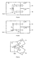
- Fig. 17 to 19 instead of construing the apparatus in an I-type configuration as of Figs. 12 and 13 it is designed as a U-type apparatus.
- the two LLPT's 1a and 1b are provided in a side by side position.
- two robots 9a and 9b are installed, each serving the modules of one of the LLPT 1a,1b via the respective openings.
- Each of the robots 9a,9b provides for a vertical up and down movement v a ,v b in a controllably driven manner.
- Each of the robots 9a,9b further provides for horizontal forth and back movement h a and h b towards and into or from the modules of the respective LLPT 1a,1b.
- the robots 9a and 9b may e.g. be principally conceived according to the robot shown in Fig. 14 with support members 15 a and 15 b not pointing from each other but being provided on one side of support 13 and in parallelism.
- the movements of the two robots 9a and 9b may be independently controlled preferably by means of a freely reprogrammable control unit (not shown). If a time-synchronous processing shall be established at the two LLPT 1a,1b, either the two independently controllable robots 9a and 9b are synchronously operated, or there is provided a single robot which serves simultaneously both LLPT 1a,1b.
- FIG. 18 Such an embodiment is shown in Fig. 18 again schematically and in a representation in analogy to that of Fig. 17 .
- one single robot 9ab which provides combined common vertical transport movement v ab of substrates into alignment with openings at the LLPT 1a and 1b
- the horizontal movements h a ,h b are either synchronised, or are controlled specifically for each LLPTM.
- FIG. 19 A third embodiment of U-shaped concept is shown in Fig. 19 .
- the one robot 9ab serves by vertical transport movement v ab and horizontal transport movement h ab both LLPT's 1a and 1b. To do so the robot 9ab performs a horizontal movement w ab as shown.
- a variant is shown in Fig. 20 , as an Y-type concept.
- the two LLPT's 1a and 1b are arranged at the transport arrangement TA so as to define an angle ⁇ .
- the robot concept is principally the same as shown in Fig. 18 .
- the single robot 9ab serves the modules of both angularly displaced LLPT 1a and 1b. Thereby, such robot may be realised very similar to that shown in Fig. 14 , thereby providing the supporting members not opposite each others but at the desired angle ⁇ about the central axis of post 13.
- a further mode of realising the robot within transport arrangement TA is shown in Fig. 21 .
- the robot 9ab is conceived to rotate about the central axis by at least the angle of ⁇ so as to serve the modules of both angularly displaced LLPT's 1a,1b.
- LLPT's allows flexible full parallel processing of different or equal multi-step processes.
- a transport robot 9 rot which is rotatable about a central axis so as to serve more than two as shown e.g. for LLPT's mounted circularly around the transport arrangement TA.
- more preferred embodiments of the apparatus according to the present invention are the two LLPT-structures of I- or U- or possibly Y-type as of Figs. 17 to 21 .
- Fig. 23 there is shown a today's preferred apparatus as used in the frame of the present invention. It is conceived according to the concept of Fig. 10 . It comprises one single LLPT which consists, from top to bottom, of a two-substrate batch processing module BPM 1 followed by a two-substrate batch input and output load lock module BLL io , followed by a second two-substrate batch processing module BPM 2 .
- the loadlock module BLL io is subdivided into a first input loadlock compartment C i , followed by a first output loadlock compartment C o , followed by a second input loadlock compartment C i and finally a second output loadlock compartment C o .
- the respective openings 33 which establish communication between BPM 1 , BLL io , BPM 2 and a transport arrangement TA, are provided with respectively controlled valves 35.
- a robot 39 which is drivingly moveable in a controlled manner in horizontal direction h and comprises a two-substrate batch transport member 41 with an upper and with a lower substrate transport fork 43 U and 43 1 .
- the overall arrangement of the two horizontal transport members 41 is drivingly moveable vertically in a controlled manner.
- the pitch between the upper substrate carrier fork 43 u and a lower substrate carrier fork 43 1 is selected to be in agreement with the pitch between the openings at each of the batch processing modules and the batch loadlock module.
- Such an apparatus is most suited to be used for processing large substrates of at least 1m 2 , preferably of at least 2m 2 , even of at least 4m 2 as for solar panel, TFT or plasma display panel manufacturing.
- process modules of the present invention may be separated from the transport chamber by valves, they can operate independently from each other if required.
Landscapes
- Engineering & Computer Science (AREA)
- Chemical & Material Sciences (AREA)
- Mechanical Engineering (AREA)
- General Engineering & Computer Science (AREA)
- Chemical Kinetics & Catalysis (AREA)
- Materials Engineering (AREA)
- Metallurgy (AREA)
- Organic Chemistry (AREA)
- General Chemical & Material Sciences (AREA)
- Container, Conveyance, Adherence, Positioning, Of Wafer (AREA)
- Physical Vapour Deposition (AREA)
Description
- The present invention is most generically directed on vacuum treating of extended relatively thin substrates as especially substrates for manufacturing solar panels, TFT display panels, or plasma display panels. Here large and thin substrates, as e.g. of glass have to be vacuum process treated thereby including deposition of semi-conductive layers.
- Industrial manufacturing of such extended substrates necessitates careful handling. Thereby it has become customary to maintain such substrates horizontally oriented during transporting and during vacuum processing in spite of the fact that particle contamination of the substrate may be more critical in a horizontal position than in mere vertical position. Horizontal transporting and processing has nevertheless considerable advantages with respect to stable, vibration free support of the substrates. With respect to techniques for handling and vacuum processing such substrates attention is drawn to the following documents
all of the same applicant as the present application.
- Further attention is drawn to the
- As the substrates to be vacuum treated and of the type mentioned above becomes lager and larger, on the one hand the apparatuses for industrially and automatically treating such substrates become larger and larger. Because the substrates are maintained during transporting and vacuum processing in horizontal orientation the apparatus for such substrate processing especially becomes large with respect to their footprint surface. Because such treating facilities or apparatus are installed in clean room ambient, this leads to an increased volume thereof which significantly raises manufacturing costs.
- Further, handling robots become larger especially under consideration of their footprint surfaces and must be tailored to safely transport such substrates between loadlocks and processing stations in the vacuum treatment facilities.
- Form the
US 5 275 709 there is known an apparatus for coating large substrates which is apparently especially compact, which is conceived with a minimum of chambers and apparently permits multilayer coating of high quality of such substrates. This known apparatus shall further apparently be comparatively inexpensive to manufacture by having a minimum of chamber wall surfaces. - The known apparatus is principally conceived with loadlock-and processing chambers vertically stacked one upon the other with a transport chamber performing substrate handling between a loadlock chamber and the processing chambers. By the fact that loadlock and processing chambers are stacked one upon the other in a tower-like concept, the overall footprint of the apparatus is minimized although handling and processing the substrates in horizontal orientation.
- More specifically the known apparatus provides for two vertical towers, one thereof consisting of an input/output loadlock chamber and processing chambers arranged beneath the loadlock chamber, the other tower consisting only of processing chambers. The two towers are arranged with workpiece handling openings facing each other on opposite sides of a central transport arrangement which has a lift type transport robot serving the openings of the two towers.
- Although the apparatus as known from this
US 5 275 709 proposes a concept which, considered from the principal of construing a multiple chamber plant by vertical stapling, minimizes its footprint surface, it has the drawback that it provides for a multiple processing facility whereat both towers are exploited to perform one single substrate multi-step process. The substrates are all input from ambient to the processing facility by one input/output loadlock chamber, are then transported as desired forth and back between processing stations at both of the towers and are finally removed from the processing facility by the said one loadlock chamber. - It is an object of the present invention on the one hand to maintain the principal tower structure concept as of the
US 5 275 709 for large substrate processing thereby further improving simplicity of substrate handling and improving flexibility with respect to treating such substrates by well defined multiple steps substrate processing. - Departing from an apparatus as just addressed this object is realized by a conception according to the characterizing part of
claim 1. - Thereby the overall processing of the substrate is done by exclusive vertical transportation of the substrates from loadlock towards the respective processing chamber as provided and by horizontal transport to serve the substrates into and from these chambers. The loadlock- and processing towers thereby defines for respective self-contained, all-in-one substrate processing modules.
- Thus at least two loadlock- and processing towers each formed by one loadlock arrangement and one processing arrangement are provided. One single transport arrangement is used to serve the two or more than two loadlock- and processing towers. Each of these towers thereby defines in a self-contained all-in-one desired multi-step substrate process inclusive input and output loadlocking the substrates. Thereby complete parallel, multi-step processing ability is realised of equal or different multi-step processes.
- In spite of the fact that more than two of the loadlock-and processing towers may be grouped around the transport chamber, an optimum structure with respect to simplicity and space, especially footprint surface, in a two loadlock-and processing tower concept with one transport chamber can be accomplished. Along the towers either identical substrate multiple step processing is performed or there is performed in each of the laodlock- and processing towers a distinct desired and different process.
- In spite of the fact that the principal according to the present invention is to perform in each of the loadlock-and processing towers provided a self-contained multiple step substrate process it shall not be excluded that there might be provided a processing chamber or compartment which is used for processing substrates from both or from a number of loadlock- and processing towers as provided. Such a commonly used compartment or chamber may for instance be a intermediate storage chamber for substrates to be longterm equalized with respect to their temperature after having been treated and before being despatched by the respective loadlock to ambient. Such a commonly used treatment compartment or chamber may be provided for instance beneath both towers as provided, thereby exploiting for substrate intermediate storage the overall footprint surface of the apparatus.
- As will be explained more in details later, the apparatus according to the present invention may be conceived to provide for single substrate or for substrate batch processing or, in a mixed mode, for single substrate and substrate batch processing along the at least one loadlock and processing tower as provided.
- In a further preferred improvement the transport robot comprises at least one substantially horizontal substrate support for at least one substrate whereby the substrate support is driven and controllably movable in a vertical direction to bring the substrate in alignment with an opening to one of the addressed towers and which is further driven and controllably movable in horizontal direction to bring the substrate support into and out of one of the towers thereby leaving such substrate in the tower for processing or loadlocking or removing such substrate from processing or from loadlocking.
- In a still further preferred improvement the substrate support is additionally rotatable about a vertical axis in a controllably driven manner. Nevertheless, if the substrate support is rotatable at all the rotational movement is preferably limited to at most 180° thereby even more preferred, to at most 45°. Nevertheless, in the today's most preferred embodiment the substrate support is exclusively moveable in a controllably driven manner linearly horizontally and vertically.
- In a further preferred improvement at least one of the processing arrangements comprises at least one substrate batch processing module wherein simultaneously more than one substrate are loaded, processed simultaneously and simultaneously removed. A further preferred embodiment, which may also be combined with substrate batch handling and processing the at least one processing arrangement, comprises at least one single substrate processing module.
- Turning to specific conception of the loadlock arrangement in preferred modes, in one preferred improvement at least one loadlock arrangement comprises an input/output loadlock arrangement whereat both loadlocking of at least one substrate from surrounding atmosphere towards the transport chamber as well as from the transport chamber towards surrounding atmosphere are performed.
- In a further preferred mode such input/output loadlock arrangement comprises at least one single substrate input loadlock chamber. In a still further mode the said imput/output loadlock arrangement comprises at least one single substrate output loadlock chamber. Still a further mode of the addressed input/output loadlock arrangement comprises at least one of a substrate batch input loadlock chamber, of a substrate batch output loadlock chamber and of an input/output substrate batch loadlock chamber.
- A further mode comprises one of the loadlock- and processing towers comprising one of an input and of output loadlock arrangement.
- A further preferred mode has exclusively two of the loadlock- and processing towers which are arranged opposite one another i.e. on opposite sides of the transport vacuum chamber and thus facing each other with their respective openings via the transport chamber. This is an I-type concept.
- In a second preferred mode the apparatus has still exclusively two loadlock- and processing towers which are arranged one aside the other and on one side of the vacuum transport chamber thereby concomitantly defining with the vacuum transport chamber a U-type footprint surface.
- In a third preferred mode, nevertheless less preferred than the just addressed second mode, the apparatus has still exclusively two loadlock- and processing towers which concomitantly define for a Y-type footprint surface together with the transport chamber.
- In a still further preferred mode the apparatus has a substrate handling and processing ability for substrates which have an extent of at least 1m2, preferably of at least 2m2 and especially preferred even of at least 4m2.
- In a further preferred mode the loadlock arrangement comprises at least one of a heating and of cooling arrangement for at least one substrate.
- According to the present invention there is further proposed a method for manufacturing two-dimensionally extended vacuum treated substrates according to the wording of claim 19.
- Thereby, in the method according to the present invention the vacuum treated substrates may be one of solar panel substrates, of TFT display panel substrates and of plasma display panels.
- The present invention will now be described more in detail with the help of figures which show examples of preferred embodiments of the present invention.
- The figures show:
- Fig. 1
- A schematic side view of a loadlock- and processing tower as an essential component for the present invention thereby additionally showing different operating modes of opening control at such tower.
- Fig. 2
- Still, in a schematic representation according to
Fig. 1 , a first variant of a loadlock- and processing tower. - Fig. 3
- In a still schematic representation in analogy to that of the
Figs. 1 or 2 , a further variant of a loadlock- and processing tower. - Fig.4
- In analogy to the representations of
Figs. 1 to 3 , a third variant of a loadlock and processing tower. - Fig. 5
- Still in a representation in analogy to that of the
Figs. 1 to 4 , a fourth variant of a loadlock-and processing tower. - Fig. 6
- Still in a representation in analogy to that of the
Figs. 1 to 5 , a fifth variant of a loadlock-and processing tower. - Fig. 7
- Still in a representation in analogy to that of the
Figs. 1 to 6 , a sixth variant of a loadlock-and processing tower. - Fig. 8
- In a schematic representation a top view upon a loadlock- and processing tower according to
Fig. 1 to 7 with a large surface substrate arranged therein. - Fig. 9
- Schematically a positioning arrangement for sustaining large substrates at specific positions within a loadlock- and processing tower.
- Fig. 10
- In a schematic side view, an apparatus comprising one single loadlock- and processing tower served by a robot in a vacuum transport chamber.
- Fig. 11
- Again in a schematic representation a top view on the apparatus according to
Fig. 10 . - Fig. 12
- In a schematic side view in analogy to the representation of
Fig. 10 , an apparatus according to the present invention and performing the method according to the present invention. - Fig. 13
- In a representation in analogy to that of
Fig. 11 , a schematic top view on the apparatus as ofFig. 12 . - Fig. 14
- In a simplified and schematic representation, a robot arrangement as e.g. provided in a transport chamber as used in the embodiment of the apparatus according to
Fig. 12 . - Fig. 15
- In a schematic top view, a substrate support as used in a robot e.g. according to
Fig. 14 for supporting substrates during handling. - Fig. 16
- In a schematic perspective view a third variant of a robot within a vacuum transport chamber as e.g. applied in the embodiment of
Fig. 12 , for handling substrates to both loadlock- and processing towers. - Fig. 17
- In a schematic top view a further preferred embodiment of an apparatus according to the present invention with two loalock- and processing towers in U-configuration.
- Fig. 18
- and
Fig. 19 in a representation in analogy to that ofFig. 17 , two further preferred embodiments of the two loadlock- and processing tower concept in U-configuration. - Fig. 20
- A further embodiment of the apparatus according to the present invention with two loadlock- and processing towers arranged with respect to a common vacuum transport chamber in Y-configuration in top view.
- Fig. 21
- The embodiment according to
Fig. 20 still in a schematic top view representation with a different mode of realising a robot within the vacuum transport chamber. - Fig. 22
- Still in a schematic top view, a further embodiment of the apparatus according to the present invention with four loadlock- and processing towers served by a common rotatable robot within a vacuum transport chamber.
- Fig. 23
- In a more detailed but still schematic representation a side view of an apparatus as shown in
Fig. 10 and11 . - In
Fig. 1 there is shown schematically the side view of a loadlock- andprocessing tower LLPT 1 as one essential part as used in the frame of the present invention. The LLPT is a vertical tower which comprises a loadlock arrangement LLA and a processing arrangement PMA. As will be exemplified later, the loadlock arrangement LLA may comprise at least one single substrate input/output loadlock chamber, at least one single substrate input loadlock chamber, at least one single substrate output loadlock chamber, at least one substrate batch input/output load lock chamber, at least one substrate batch input loadlock chamber, at least one substrate batch output loadlock chamber. - Thus, principally the loadlock arrangement LLA of the
LLPT 1 comprises at least one loadlock chamber. The loadlock arrangement LLA as ofFig. 1 communicates on the one hand with an outside atmosphere AT as with ambient atmosphere, and on the other hand with a vacuum atmosphere V in atransport arrangement TA 2. The double line/double direction arrows inFig. 1 indicate most generically two-directional handling of one or more than one substrate between the atmosphere AT, the interior of the loadlock arrangement LLA and thetransport arrangement TA 2. - Nevertheless, it must be pointed out that in some configurations of an overall apparatus according to the present invention, a
LLPT 1 may have a loadlock arrangement LLA which has only an input load lock arrangement or only an output load lock arrangement, i.e. a loadlock arrangement for transmitting substrates from the atmosphere AT towards thetransport arrangement TA 2, or for transmitting substrates from thetransport arrangement TA 2 towards the atmosphere AT. - As further schematically shown handling of the one or more than one substrate between the loadlock arrangement LLA and atmosphere AT as well as the
transport arrangement TA 2 is performed via respective openings O which are sealably and controllably closable by respective loadlock valves, as schematically shown inFig. 1 by the controllable, sealably closable openings Os. - The loadlock- and
processing tower LLPT 1 further comprises a process module arrangement PMA which comprises one or preferably more than one processing chambers. Such processing chambers may thereby be single substrate processing chambers or substrate batch processing chambers. Therein the respective substrates or substrate batches are processed by a vacuum treatment process, thereby e.g. by a CVD, PECVD, PVD process, or by heating, cooling, etc. With respect to substrate heating and/or cooling, nevertheless such processing may be performed exclusively or additionally within the LLA. - As further schematically shown in
Fig. 1 , generically the PMA and the transport arrangement TA are in two-directional substrate handling communication. Further and dependent on the type of processes performed in the PMA and their specific requirements with respect to cleanliness, such bidirectional substrate handling between PMA and TA occurs via openings O which are, as also schematically shown inFig. 1 permanent open, OP, controllably closable but not sealingly closable, Ops, or controllably and sealingly closable, Os. - The important feature of the loadlock- and
processing tower LLPT 1 is that, vertically stacked, there is provided a loadlock arrangement LLA and a processing module arrangement PMA. -
Figs. 2 to 7 show in representations in analogy to that ofFig. 1 , different preferred forms of realising theLLPT 1. - According to
Fig. 2 theLLPT 1 comprises a number, for instance and as shown, three single substrate input/output loadlock stations LLio forming the LLA according toFig. 1 . The PMA in the embodiment ofFig. 2 consists of a further number, for instance again three single substrate processing chambers PM1 to PM3. - In the embodiment of the
LLPT 1 ofFig. 3 the structure of LLA is the same as in the embodiment ofFig. 2 . The PMA consists of a single substrate batch processing module BPM. In the embodiment ofFig. 4 the process module arrangement PMA is in fact equal to that as shown inFig. 2 . The loadlock arrangement LLA consists here of a first number of input single substrate loadlock modules LLi and of a second number as of output loadlock modules LLo. In the embodiment ofFig. 5 the load lock arrangement LLA is conceived equally to the LLA of the embodiment ofFig. 4 , whereas the processing module arrangement PMA consists of a batch processing module BPM as of the embodiment ofFig. 3 . - The embodiment of the
LLPT 1 as ofFig. 6 consists of a process module arrangement PMA realised e.g. as shown in one of the embodiments ofFigs. 2 to 5 . The loadlock arrangement LLA consists of a substrate batch input/output load lock chamber BLLio. According to the embodiment as schematized inFig. 7 still with a process module arrangement PMA, e.g. as exemplified at the embodiments ofFigs. 2 to 5 , the load lock arrangement LLA consists of a substrate batch input load lock module BLLi and of a substrate batch output load lock module BLLo. - These examples of preferred embodiments do clearly teach the skilled artisan how to combine specifically tailored loadlock- and process modules to perform predetermined substrate processing, thereby maintaining the basic concept of the
LLPT 1, namely of having a vertical tower with a loadlock arrangement and with a processing module arrangement. - Taking e.g. the embodiment of
Fig. 2 , in some instances it might be advantageous not to subdivide the vertical extent of theLLPT 1 into an upper loadlock- and a bottom process module arrangement, but to mix up modules of the LLA and modules of the PMA along the vertical extent of the loadlock- andprocessing tower LLPT 1. As was outlined in the introductory part of the present description, the present invention is especially directed on vacuum treating large two-dimensionally extended substrates, e.g. with sizes of at least 1m2, preferably of at least 2m2, and even of 4m2 and more. - Thereby, in a most preferred embodiment of the present invention overall processing, inclusive loadlocking, is performed with the substrates in horizontal position. This allows safe overall handling of the large surface and relatively thin substrates. In horizontal position they may be accurately held, during loadlocking transitions, during processing, and during transporting within the processing apparatus.
- In
Fig. 8 there is schematically shown a top view upon aLLPT 1 as ofFigs. 1 to 7 with alarge surface substrate 3 positioned therein. Such positioning is preferably applied in the loadlock arrangement LLA as well as in the process module arrangement PMA.Fig. 9 schematically shows in a side view a part of abottom wall 5, be it of a module of the load lock arrangement LLA, be it of a module of the processing module arrangement PMA. Alarge substrate 3 is deposited on a positioning arrangement which comprises, as schematically shown inFig. 9 , e.g. a member ofdistinct deposition pins 7 whereupon, the thin andlarge extent substrate 3 resides. - With respect to possible constructions of process modules of the process module arrangement PMA and/or of loadlock modules of the load lock arrangement LLA, specific attention is drawn to the
US 6 296 735 thereby specifically to itsFigs. 1, 2, 3 ,5 to 11 ,15 to 22 , and the respective description, further to theUS 5 515 986Figs. 1, 2, 3 ,5 to 9 further to theUS 6 177 129 thereby especially toFigs. 1 to 4 ,7 to 8 as concerns process module- and loadlock module conception, handling of the substrates as by the present transport arrangement Ti and as will be described more in detail and as concerns overall timing and processing as will also be addressed more specifically later. Here also this document shall specifically be addressed with respective possible conception of process module and/or load lock module within the respective load lock arrangement and process module arrangement. Nevertheless, it must be pointed out that providing in one single tower as here described with respect to theFigs. 1 to 9 load lock arrangement and processing module arrangement, it is not taught in the documents, just mentioned. - In the following description we will refer to the previously described
LLPT 1 per se, which means that any kind of its detailed structure, as was exemplified with respect to theFigs. 1 to 9 , may be applied. Only if specific measures should be or preferably are taken in consideration such LLPT in a specific embodiment to be described, then such embodiment of a LLPT will specifically be addressed. - Still addressing basics as used in the present invention, which invention is addressed later, in
Fig. 10 there is shown schematically a side view of an embodiment of an apparatus for manufacturing vacuum treated, substantially plane substrates. This embodiment essentially consists of onesingle LLPT 1. TheLLPT 1 communicates by respective loadlock- and process module-openings, which are vertically aligned, with atransport arrangement TA 2 which latter performs handling of the substrates into and from the loadlock arrangement LLA as well as into and from the process module arrangement PMA. Thetransport arrangement 2 comprises atransport robot 9 which performs substrate transport according to h horizontally into and from respective modules of the loadlock arrangement LLA and of the process module arrangement PMA and further performs vertical transport v from a position aligned with at least one respective first opening towards alignment with at least one respective second opening of the PMA and LLA.Fig. 11 schematically shows the apparatus as ofFig. 10 in top view. - Thus, the apparatus comprises one
transport arrangement TA 2 which serves onesingle LLPT 1 which latter comprises a loadlock arrangement LLA as well as process module arrangement PMA. Thereby, the loadlock arrangement LLA comprises input/output loadlocking ability as schematically shown inFig. 10 by the double arrow i/o. In this embodiment theLLPT 1 defines for all loadlocking and processing which is necessary for a predetermined multiprocessing step treatment of at least one substrate. Thetransport arrangement TA 2 is provided to serve the substrate between respective openings at theLLPT 1. Thetransport arrangement TA 2 needs only perform by its robotic transportingmember 9 horizontal - h - and vertical - v - transport movements. Whenever a different processing with different processing steps is to be performed on substrates, only theLLPT 1 must be exchanged. Due to the fact that all the modules or stations which are necessary for an intended substrate processing are stapled vertically one upon the other to result in the addressedLLPT 1, the footprint of all the modules necessary for such processing is a minimum. Additionally, the footprint of the transport arrangement is minimum as necessary to serve horizontally the respective modules of the LLA and PMA. In opposition to the teaching of theUS 5 275 709Fig. 10 and11 in fact provides for a tower of modules which provide for all processing steps desired inclusive inputting and outputting the substrates to and from processing stations. - In
Figs. 12 and 13 there is now shown, again schematically, an embodiment of an apparatus according to the present invention performing a manufacturing method according to the present invention. Thereby, afirst LLPT 1a and asecond LLPT 1b are both in communication with a common transport arrangement TA. The conceptions of the LLAa of thefirst LLPT 1a as well as of PMAa of thatfirst LLPT 1a are selected to perform a first well-defined processing sequence with different processing steps uponsubstrates 3a. - At the
second LLPT 1b the LLAb as well as the PMAb are conceived to perform a second process on a different set ofsubstrate 3b. Thereby, the two process-sequences at therespective towers tower - As shown in the
Figs. 12 and 13 , the transport arrangement 2ab has the ability to perform horizontal and vertical substrate transport with respect to thefirst LLPT 1a and with respect to thesecond LLPT 1b completely independently. A robot 9ab is controlled to perform horizontal transportation ha with respect totower 1a independently from such horizontal transportation hb with respect to thesecond tower 1b and in analogy to perform vertical va transportation of substrates processed intower 1a independently from such transport vb with respect to thesecond tower 1b. - In
Fig. 14 there is schematically shown a robot 11 which may be applied within the vacuum chamber of the transport arrangement TA as offigure 12 and 13 . - According to
Fig. 14 there is provided within the vacuum chamber of the transport arrangements (not shown) a stationarycentral support post 13. For handling large substantially flat and horizontally positionedsubstrates 3a with respect tom theLLPT 1a ofFig. 12 and 13 , at the one side ofpost 13 there is provided a first sliding arrangement 14a which is vertically slideable - va - in controlled driven manner. Mounted to sliding arrangement 14a there is provided a number of single substrate supporting member 15a, as shown e.g. three. They project horizontally and are vertically mounted distant form each other and, in one preferred embodiment, with a controllably variable pitch distance pa. Thus the pitch distance pa in this preferred embodiment may be controllably varied, e.g. to accommodate for substrate handling openings at the LLA and/or PMA with different vertical pitch distances. - Each of the supporting members 15a may be expanded and retracted horizontally - h -, driven by telescopic drives, as shown within encapsulations 17a. The supporting members 15a have supports with supporting pins 20 whereupon the
substrates 3a to be processed inLLPT 1a are disposed during horizontal and vertical transport. There is further provided a second sliding arrangement 14b opposite sliding arrangement 14a alongpost 13, which is construed with supporting members 15b, supports 19b supporting pins 20b, encapsulates 17b very much like the arrangement mounted on slide 14a whereby, as shown, the number of supporting members 15b which do handlesubstrates 3b with respect toLLPT 1b as offigure 12 or 13 needs not to be equal with the number of members 15a for servingsubstrate 3a to be processed by aLLPT 1a. - Preferably, the horizontally
movable supports Fig. 15 . In dashed line representation,Fig. 15 shows arespective substrate 3a,b residing on the support 19a,b and being thereby deposited on support pins 21 in a LLA or PMA. - With the second preferred embodiment as of
Figs. 12 to 15 there is provided an apparatus according to the present invention with two distinct loadlock- and processing towers LLPT 1a and 1b which each provide for the complete set of modules to perform substrate processing inclusive feeding such substrate from surrounding atmosphere AT to the vacuum processing and from vacuum processing back to surrounding atmosphere. - The robot 9ab within the transport arrangements TA 2ab needs not perform any rotational movement. Substrate transport is realised merely by horizontal - h - and vertical - v - substrate movement.
- As schematically shown in
Fig. 14 , a controllingunit 21 is provided for controlling the horizontal transport movements ha,b, the vertical transport movements va,b with respect to their extent, timing of respective horizontal and vertical transport cycles as well as, if necessary, pitch distance pa of the respective support arrangements. Such acontrol unit 21 is preferably realised as a free programmable unit so that in dependency of an intended processing especially timing of the transport cycles may flexibly be adapted. Such a controllingunit 21 preferably also controls processing and loadlock cycles as schematically shown inFig. 14 with the control connections to LLAab and PMAab. - Taking into account that in most multiple step processing treatments of substrates the time amount necessitated to perform a respective vacuum treatment within a process module of PMA and the time amount for feeding substrate through the loadlock arrangement LLA will be larger than the time amount for transporting a substrate or a batch of substrates from one module to another, in further preferred embodiment, the transport robot within transport arrangement TA 9ab in fact provides only for one single up/down moving facility.
- According to
Fig. 16 such robot comprises adrawerlike member 25 which is controllably drivable in vertical direction v up and downguide 27. - Within drawerlike
member 25, again controllably drivable and moveable in horizontal direction h there is provided aslide 29 which has a frame or forklike shape and which may be horizontal driven into a respective module of the loadlock - or process module arrangement. - As shown in dashed lines in
Fig. 16 , this embodiment of a transport robot provides the possibility to propel theslide 29 to the left or to the right hand side of theguide members 27. - By the embodiment of
Fig. 16 serving a common treatment module without rotation of the substrates around the vertical axis in the transport arrangement is achieved. - Nevertheless, such rotation free handling may also be realised by a robot different than shown in
Fig. 16 . - The apparatus according to the present invention in its most preferred embodiments as of
Figs. 10 and12 does not necessitate any rotational movement about the vertical axis of a robot handling the substrates. The embodiment as ofFig. 12 may be called I-type due to its I-shaped footprint. - In the
Figs. 17 ,18, and 19 further preferred embodiments of the apparatus according to the present invention are schematically shown representations in analogy to that ofFig. 13 . These embodiments do also not necessitate any rotational movement of a robot within the transport arrangement TA, about a vertical axis, so as to serve the openings of the LLPT's. - According to
Fig. 17 to 19 , instead of construing the apparatus in an I-type configuration as ofFigs. 12 and 13 it is designed as a U-type apparatus. According toFig. 17 , the two LLPT's 1a and 1b are provided in a side by side position. In the vacuum chamber of the transport arrangement TA tworobots LLPT robots robots respective LLPT - The
robots Fig. 14 with support members 15a and 15b not pointing from each other but being provided on one side ofsupport 13 and in parallelism. The movements of the tworobots LLPT controllable robots LLPT - Such an embodiment is shown in
Fig. 18 again schematically and in a representation in analogy to that ofFig. 17 . As clearly be seen, there is provided one single robot 9ab which provides combined common vertical transport movement vab of substrates into alignment with openings at theLLPT - A third embodiment of U-shaped concept is shown in
Fig. 19 . Here again only one single robot 9ab is provided. The one robot 9ab serves by vertical transport movement vab and horizontal transport movement hab both LLPT's 1a and 1b. To do so the robot 9ab performs a horizontal movement wab as shown. - From the concepts as shown schematically in the
Figs. 17 to 19 a variant is shown inFig. 20 , as an Y-type concept. Here the two LLPT's 1a and 1b are arranged at the transport arrangement TA so as to define an angle ϕ. InFig. 20 the robot concept is principally the same as shown inFig. 18 . The single robot 9ab serves the modules of both angularly displacedLLPT Fig. 14 , thereby providing the supporting members not opposite each others but at the desired angle ϕ about the central axis ofpost 13. - For such an Y-type embodiment of the apparatus a further mode of realising the robot within transport arrangement TA, principally according to
Fig. 19 , is shown inFig. 21 . The robot 9ab is conceived to rotate about the central axis by at least the angle of ϕ so as to serve the modules of both angularly displaced LLPT's 1a,1b. - As was mentioned above, providing two or more LLPT's allows flexible full parallel processing of different or equal multi-step processes. Following up this concept it is absolutely possible as shown in
Fig. 22 to conceive the transport arrangement with atransport robot 9rot which is rotatable about a central axis so as to serve more than two as shown e.g. for LLPT's mounted circularly around the transport arrangement TA. Nevertheless, more preferred embodiments of the apparatus according to the present invention are the two LLPT-structures of I- or U- or possibly Y-type as ofFigs. 17 to 21 . - In
Fig. 23 there is shown a today's preferred apparatus as used in the frame of the present invention. It is conceived according to the concept ofFig. 10 . It comprises one single LLPT which consists, from top to bottom, of a two-substrate batch processing module BPM1 followed by a two-substrate batch input and output load lock module BLLio, followed by a second two-substrate batch processing module BPM2. Thereby, the loadlock module BLLio is subdivided into a first input loadlock compartment Ci, followed by a first output loadlock compartment Co, followed by a second input loadlock compartment Ci and finally a second output loadlock compartment Co. Therespective openings 33 which establish communication between BPM1, BLLio, BPM2 and a transport arrangement TA, are provided with respectively controlledvalves 35. - Within the transport arrangement TA-
chamber 37 there is provided arobot 39 which is drivingly moveable in a controlled manner in horizontal direction h and comprises a two-substratebatch transport member 41 with an upper and with a lower substrate transport fork 43U and 431. The overall arrangement of the twohorizontal transport members 41 is drivingly moveable vertically in a controlled manner. The pitch between the upper substrate carrier fork 43u and a lower substrate carrier fork 431 is selected to be in agreement with the pitch between the openings at each of the batch processing modules and the batch loadlock module. - Such an apparatus is most suited to be used for processing large substrates of at least 1m2, preferably of at least 2m2, even of at least 4m2 as for solar panel, TFT or plasma display panel manufacturing. As the process modules of the present invention may be separated from the transport chamber by valves, they can operate independently from each other if required.
- With respect to further details we refer to:
- ●
US 6 177 129 with respect to overall timing and cycle control preferably in a reprogrammable technique as well as with respect to possible implementation of flexible robot technique cooperating with process- or loadlock modules. - ●
US 6 533 534 ; - ●
US 5 515 986 - ●
US 6 296 375 with respect to techniques of conceiving process module, loadlock module and their serving by robot members for treating horizontally oriented flat substrates.
Claims (19)
- An apparatus for vacuum treating two-dimensionally extended substrates comprising(a) a vacuum transport chamber (TA) with a transport robot (9ab) arrangement;(b) a processing arrangement (PMAa) with at least one processing station communicating by at least one workpiece pass-through opening (Os) with said vacuum transport chamber (TA);(c) a loadlock arrangement (LLAa) communicating by at least one workpiece pass-through opening (Os) with said vacuum transport chamber (TA)and by at least one further workpiece pass-through opening (Os) with an atmosphere (AT) outside said vacuum transport chamber (TA) and said processing arrangement (PMAa);(d1) a loadlock- and processing tower (1, LLPT1) formed by said processing arrangement (PMAa) and said loadlock arrangement (LLAa) arranged vertically one upon the other;characterized by comprising at least two of said loadlock-and processing towers (1a, 1b; LLPT1a, LLPT1b).
- The apparatus of claim 1, wherein said transport robot (9ab) comprises at least one substantially horizontal substrate support (15a) for at least one substrate (3b), said substrate support being driven and controllably movable in vertical direction (v) as well as in horizontal direction (h) into alignment with said openings (Os) and into and from said at least two loadlock- and processing towers (1a, 1b; LLPT1a, LLPT1b).
- The apparatus of claim 2, wherein said substrate support is additionally rotatable (ϕ) about a vertical axis in a controllably driven manner.
- The apparatus of claim 3, wherein said rotational movement is limited to at most 180°.
- The apparatus of claim 4, wherein said rotational movement is limited to at most 45°.
- The apparatus of claim 1, wherein said transport robot comprises at least one horizontal substrate support (15a) for at least one substrate (3a) which support is driven exclusively in vertical (v) and in horizontal (h) direction, in a respectively controlled manner.
- The apparatus of claim 1, wherein at least one of said processing arrangements (PMAa, PMAb) comprises at least one substrate-batch processing module.
- The apparatus of claim 1, wherein at least one of said processing arrangements (PMAa, PMAb) comprises at least one single substrate processing module.
- The apparatus of claim 1, wherein at least one of said loadlock arrangements (LLAa, LLAb) comprises an input/output loadlock arrangement.
- The apparatus of claim 9, wherein said input/output loadlock arrangement comprises at least one single substrate input loadlock chamber.
- The apparatus of claim 9, wherein said input/output loadlock arrangement comprises at least one single substrate output loadlock chamber.
- The apparatus of claim 9, wherein said input/output loadlock arrangement comprises at least one of a substrate batch input loadlock chamber, of a substrate batch output loadlock chamber and of an input/output substrate batch loadlock chamber.
- The apparatus of claim 1, wherein one of said loadlock and processing towers comprises one of an input (LLi) and of an output (LLo) loadlock arrangement.
- The apparatus of claim 1, wherein exclusively two of said loadlock and processing towers (1a, 1b) are provided arranged on opposite sides of said transport vacuum chamber (TA) and facing each other.
- The apparatus of claim 1, wherein exclusively two of said loadlock and processing towers (1a, 1b) are provided arranged one aside the other on one side of said vacuum transport chamber (TA), said tower and said vacuum transport chamber concomitantly defining for a U-shaped footprint.
- The apparatus of claim 1, wherein exclusively two of said loadlock- and processing towers (1a, 1b) are provided with said vacuum transport chamber (TA) defining concomitantly a Y-shaped footprint.
- The apparatus of claim 1, wherein said substrate has an extent of at least 1m2, preferably of at least 2 m2 and even preferably of at least 4m2.
- The apparatus of claim 1, herein said loadlock arrangement comprises at least one of a heating and of a cooling arrangement for at least one substrate.
- A method for manufacturing two-dimensionally extended vacuum treated substrates, comprising the steps of:● performing by a loadlock arrangement (LLAa) and by a processing arrangement (PMAa) of a first loadlock-and processing tower (1a; LLPT1a) a first processing sequence upon first set of substrates (3a), said loadlock arrangement (LLAa) and said processing arrangement (PMAa) being arranged vertically stacked;● performing by a loadlock arrangement (LLAb) and by a processing arrangement (PMAb) of a second loadlock-and processing tower (1b; LLPT1b) a second processing sequence upon second set of substrates (3b), said loadlock arrangement (LLAb) and said processing arrangement (LLPT1b) being arranged vertically stacked;● said first and second sets of substrates being different sets;● performing transport of said different sets of substrates with respect to the first (1a; LLPT1a) and with respect to the second (1b; LLPT1b) loadlock- and processing towers independently, horizontally and vertically, by a robot (9ab) of a transport arrangement common to both processing towers.
Applications Claiming Priority (3)
| Application Number | Priority Date | Filing Date | Title |
|---|---|---|---|
| US42669702P | 2002-11-15 | 2002-11-15 | |
| US426697P | 2002-11-15 | ||
| PCT/CH2003/000742 WO2004046416A1 (en) | 2002-11-15 | 2003-11-12 | Apparatus for vacuum treating two dimensionally extended substrates and method for manufacturing such substrates |
Publications (2)
| Publication Number | Publication Date |
|---|---|
| EP1560944A1 EP1560944A1 (en) | 2005-08-10 |
| EP1560944B1 true EP1560944B1 (en) | 2014-03-05 |
Family
ID=32326404
Family Applications (1)
| Application Number | Title | Priority Date | Filing Date |
|---|---|---|---|
| EP03769143.3A Expired - Lifetime EP1560944B1 (en) | 2002-11-15 | 2003-11-12 | Apparatus for vacuum treating two dimensionally extended substrates and method for manufacturing such substrates |
Country Status (8)
| Country | Link |
|---|---|
| US (2) | US7244086B2 (en) |
| EP (1) | EP1560944B1 (en) |
| JP (1) | JP2006506818A (en) |
| KR (1) | KR101120497B1 (en) |
| CN (1) | CN1711369B (en) |
| AU (1) | AU2003277790A1 (en) |
| TW (1) | TW200414297A (en) |
| WO (1) | WO2004046416A1 (en) |
Families Citing this family (25)
| Publication number | Priority date | Publication date | Assignee | Title |
|---|---|---|---|---|
| JPH0936198A (en) * | 1995-07-19 | 1997-02-07 | Hitachi Ltd | Vacuum processing apparatus and semiconductor manufacturing line using the same |
| NL1028907C2 (en) * | 2005-04-29 | 2006-10-31 | Fico Bv | Method and device for supplying and removing carriers with electronic components. |
| KR100737716B1 (en) * | 2005-05-26 | 2007-07-10 | 주식회사 에이디피엔지니어링 | Plasma processing equipment |
| US7628574B2 (en) * | 2006-03-28 | 2009-12-08 | Arcus Technology, Inc. | Apparatus and method for processing substrates using one or more vacuum transfer chamber units |
| ITBS20060208A1 (en) * | 2006-11-30 | 2008-06-01 | Estral Spa | METHOD AND PLANT FOR THE THERMAL TREATMENT OF METAL ELEMENTS |
| JP5795162B2 (en) * | 2007-05-18 | 2015-10-14 | ブルックス オートメーション インコーポレイテッド | Loadlock fast exhaust and ventilation |
| US10541157B2 (en) | 2007-05-18 | 2020-01-21 | Brooks Automation, Inc. | Load lock fast pump vent |
| US20100047954A1 (en) * | 2007-08-31 | 2010-02-25 | Su Tzay-Fa Jeff | Photovoltaic production line |
| US8225496B2 (en) | 2007-08-31 | 2012-07-24 | Applied Materials, Inc. | Automated integrated solar cell production line composed of a plurality of automated modules and tools including an autoclave for curing solar devices that have been laminated |
| KR101046520B1 (en) | 2007-09-07 | 2011-07-04 | 어플라이드 머티어리얼스, 인코포레이티드 | Source gas flow path control in pecvd system to control a by-product film deposition on inside chamber |
| US20090188603A1 (en) * | 2008-01-25 | 2009-07-30 | Applied Materials, Inc. | Method and apparatus for controlling laminator temperature on a solar cell |
| JP5139253B2 (en) * | 2008-12-18 | 2013-02-06 | 東京エレクトロン株式会社 | Vacuum processing device and vacuum transfer device |
| US20100162954A1 (en) * | 2008-12-31 | 2010-07-01 | Lawrence Chung-Lai Lei | Integrated facility and process chamber for substrate processing |
| US8367565B2 (en) * | 2008-12-31 | 2013-02-05 | Archers Inc. | Methods and systems of transferring, docking and processing substrates |
| US20100162955A1 (en) * | 2008-12-31 | 2010-07-01 | Lawrence Chung-Lai Lei | Systems and methods for substrate processing |
| US8110511B2 (en) * | 2009-01-03 | 2012-02-07 | Archers Inc. | Methods and systems of transferring a substrate to minimize heat loss |
| US7897525B2 (en) * | 2008-12-31 | 2011-03-01 | Archers Inc. | Methods and systems of transferring, docking and processing substrates |
| JP5037551B2 (en) * | 2009-03-24 | 2012-09-26 | 東京エレクトロン株式会社 | Substrate replacement mechanism and substrate replacement method |
| WO2012017653A1 (en) * | 2010-08-06 | 2012-02-09 | 東京エレクトロン株式会社 | Substrate processing system, transfer module, substrate processing method, and method for manufacturing semiconductor element |
| US20130340939A1 (en) * | 2012-06-21 | 2013-12-26 | Tel Solar Ag | System for substrate handling and processing |
| JP6902379B2 (en) * | 2017-03-31 | 2021-07-14 | 東京エレクトロン株式会社 | Processing system |
| KR102837677B1 (en) * | 2018-05-15 | 2025-07-24 | 에바텍 아크티엔게젤샤프트 | Substrate vacuum treatment device and method for vacuum treatment of substrate |
| DE102018216878A1 (en) * | 2018-10-01 | 2020-04-02 | centrotherm international AG | Transport unit for parallel retraction or extension of substrate carriers, in parallel process tubes and method for simultaneous loading of parallel, horizontally spaced process tubes |
| US11965682B2 (en) | 2020-12-16 | 2024-04-23 | Samsung Electronics Co., Ltd. | Air conditioner |
| US20240087924A1 (en) * | 2022-09-12 | 2024-03-14 | Hine Automation, Llc | Multi-chamber Configuration |
Family Cites Families (35)
| Publication number | Priority date | Publication date | Assignee | Title |
|---|---|---|---|---|
| US2933207A (en) * | 1957-06-19 | 1960-04-19 | Structural Clay Products Res F | Unit stacking apparatus |
| US5288852A (en) * | 1984-03-06 | 1994-02-22 | Dainippon Pharmaceutical Co., Ltd. | Human tumor necrosis factor polypeptides |
| US4951601A (en) * | 1986-12-19 | 1990-08-28 | Applied Materials, Inc. | Multi-chamber integrated process system |
| WO1991004213A1 (en) * | 1989-09-12 | 1991-04-04 | Rapro Technology, Inc. | Automated wafer transport system |
| CA2112682C (en) | 1991-07-03 | 2002-04-23 | Michael A. Teitel | Virtual image display device |
| US5275709A (en) | 1991-11-07 | 1994-01-04 | Leybold Aktiengesellschaft | Apparatus for coating substrates, preferably flat, more or less plate-like substrates |
| ES2090893T3 (en) | 1993-01-28 | 1996-10-16 | Applied Materials Inc | VACUUM TREATMENT APPARATUS THAT HAS AN IMPROVED PRODUCTION CAPACITY. |
| US6296735B1 (en) | 1993-05-03 | 2001-10-02 | Unaxis Balzers Aktiengesellschaft | Plasma treatment apparatus and method for operation same |
| CH687986A5 (en) | 1993-05-03 | 1997-04-15 | Balzers Hochvakuum | Plasma treatment equipment and method for its operation. |
| CH687987A5 (en) | 1993-05-03 | 1997-04-15 | Balzers Hochvakuum | A process for the increase of the deposition rate in a plasma discharge space and plasma chamber. |
| KR100244041B1 (en) * | 1995-08-05 | 2000-02-01 | 엔도 마코토 | Substrate processing apparatus |
| US5820366A (en) | 1996-07-10 | 1998-10-13 | Eaton Corporation | Dual vertical thermal processing furnace |
| KR100234539B1 (en) | 1996-12-24 | 1999-12-15 | 윤종용 | Etching Device for Semiconductor Device Manufacturing |
| US6099643A (en) * | 1996-12-26 | 2000-08-08 | Dainippon Screen Mfg. Co., Ltd. | Apparatus for processing a substrate providing an efficient arrangement and atmospheric isolation of chemical treatment section |
| US6391377B1 (en) | 1997-07-08 | 2002-05-21 | Unaxis Balzers Aktiengesellschaft | Process for vacuum treating workpieces, and corresponding process equipment |
| TW589391B (en) | 1997-07-08 | 2004-06-01 | Unaxis Trading Ag | Process for vacuum treating workpieces, and corresponding process equipment |
| JPH11129184A (en) * | 1997-09-01 | 1999-05-18 | Dainippon Screen Mfg Co Ltd | Substrate processing device and substrate loading / unloading device |
| US6053687A (en) | 1997-09-05 | 2000-04-25 | Applied Materials, Inc. | Cost effective modular-linear wafer processing |
| KR100265287B1 (en) | 1998-04-21 | 2000-10-02 | 윤종용 | Multi-chamber system for etching equipment for manufacturing semiconductor device |
| JP2965038B1 (en) * | 1998-09-21 | 1999-10-18 | 日新電機株式会社 | Vacuum processing equipment |
| JP2000195925A (en) * | 1998-12-28 | 2000-07-14 | Anelva Corp | Substrate processing equipment |
| JP3455458B2 (en) * | 1999-02-01 | 2003-10-14 | 東京エレクトロン株式会社 | Coating and developing apparatus and substrate recycling system in coating and developing processing |
| US6610150B1 (en) * | 1999-04-02 | 2003-08-26 | Asml Us, Inc. | Semiconductor wafer processing system with vertically-stacked process chambers and single-axis dual-wafer transfer system |
| JP3442686B2 (en) * | 1999-06-01 | 2003-09-02 | 東京エレクトロン株式会社 | Substrate processing equipment |
| US6318945B1 (en) * | 1999-07-28 | 2001-11-20 | Brooks Automation, Inc. | Substrate processing apparatus with vertically stacked load lock and substrate transport robot |
| US6402400B1 (en) * | 1999-10-06 | 2002-06-11 | Tokyo Electron Limited | Substrate processing apparatus |
| US6402401B1 (en) * | 1999-10-19 | 2002-06-11 | Tokyo Electron Limited | Substrate processing apparatus and substrate processing method |
| US6296375B1 (en) | 2000-01-05 | 2001-10-02 | Maxlite-Sk America, Inc. | Compact fluorescent lamp having a detachable translucent cover |
| SG94851A1 (en) * | 2000-07-12 | 2003-03-18 | Tokyo Electron Ltd | Substrate processing apparatus and substrate processing method |
| JP4004248B2 (en) * | 2000-09-01 | 2007-11-07 | 大日本スクリーン製造株式会社 | Substrate processing apparatus and substrate inspection method |
| KR100398877B1 (en) * | 2001-05-09 | 2003-09-19 | 삼성전자주식회사 | Image forming apparatus having structure for preventing noise and vibration of developing device |
| JP2003077974A (en) * | 2001-08-31 | 2003-03-14 | Hitachi Kokusai Electric Inc | Substrate processing apparatus and method of manufacturing semiconductor device |
| US7351291B2 (en) * | 2002-02-20 | 2008-04-01 | Tokyo Electron Limited | Semiconductor processing system |
| US7335277B2 (en) * | 2003-09-08 | 2008-02-26 | Hitachi High-Technologies Corporation | Vacuum processing apparatus |
| JP4246654B2 (en) * | 2004-03-08 | 2009-04-02 | 株式会社日立ハイテクノロジーズ | Vacuum processing equipment |
-
2003
- 2003-11-12 AU AU2003277790A patent/AU2003277790A1/en not_active Abandoned
- 2003-11-12 EP EP03769143.3A patent/EP1560944B1/en not_active Expired - Lifetime
- 2003-11-12 JP JP2004552336A patent/JP2006506818A/en not_active Withdrawn
- 2003-11-12 WO PCT/CH2003/000742 patent/WO2004046416A1/en not_active Ceased
- 2003-11-12 CN CN2003801032739A patent/CN1711369B/en not_active Expired - Fee Related
- 2003-11-12 KR KR1020057008231A patent/KR101120497B1/en not_active Expired - Fee Related
- 2003-11-14 TW TW092131975A patent/TW200414297A/en unknown
- 2003-11-14 US US10/713,339 patent/US7244086B2/en not_active Expired - Fee Related
-
2007
- 2007-05-30 US US11/755,423 patent/US20080038095A1/en not_active Abandoned
Also Published As
| Publication number | Publication date |
|---|---|
| EP1560944A1 (en) | 2005-08-10 |
| AU2003277790A1 (en) | 2004-06-15 |
| US20040115032A1 (en) | 2004-06-17 |
| CN1711369A (en) | 2005-12-21 |
| JP2006506818A (en) | 2006-02-23 |
| TW200414297A (en) | 2004-08-01 |
| KR101120497B1 (en) | 2012-02-29 |
| CN1711369B (en) | 2011-07-13 |
| WO2004046416A1 (en) | 2004-06-03 |
| KR20050086451A (en) | 2005-08-30 |
| US7244086B2 (en) | 2007-07-17 |
| US20080038095A1 (en) | 2008-02-14 |
Similar Documents
| Publication | Publication Date | Title |
|---|---|---|
| US7244086B2 (en) | Apparatus for vacuum treating two dimensionally extended substrates and method for manufacturing such substrates | |
| EP2207909B1 (en) | Method for manufacturing workpieces and apparatus | |
| US6183615B1 (en) | Transport system for wafer processing line | |
| US6846149B2 (en) | Semiconductor wafer processing system with vertically-stacked process chambers and single-axis dual-wafer transfer system | |
| TWI553765B (en) | Vacuum processing equipment | |
| US7628574B2 (en) | Apparatus and method for processing substrates using one or more vacuum transfer chamber units | |
| US20150243490A1 (en) | Substrate processing apparatus and substrate processing method | |
| CN102246286A (en) | Vacuum processing apparatus and vacuum transfer apparatus | |
| TW201145443A (en) | Substrate load and unload mechanisms for high throughput | |
| US9048271B2 (en) | Modular semiconductor processing system | |
| US20160293459A1 (en) | Apparatus for processing sustrate and semiconductor fabrication line including the same | |
| US6177129B1 (en) | Process for handling workpieces and apparatus therefor | |
| KR20050042191A (en) | Large area substrate processing system | |
| KR20180066192A (en) | Vacuum processor | |
| JP4838357B2 (en) | Vacuum transfer device | |
| KR102058985B1 (en) | Load station | |
| US20010051081A1 (en) | Processes for vacuum treating workpieces, and corresponding process equipment | |
| JP6833610B2 (en) | Evaporative Sources for Organic Materials, Devices with Evaporative Sources for Organic Materials, Systems with Evaporative Accumulation Devices Containing Evaporative Sources for Organic Materials, and Methods for Manipulating Evaporative Sources for Organic Materials | |
| CN113451186B (en) | Transfer robot and substrate processing system including the same | |
| TW202329303A (en) | Wafer processing equipment, wafer processing system and control method | |
| EP3706162A1 (en) | Substrate accommodation device | |
| KR101413243B1 (en) | Wafer transfer module and thin-film evaporation apparatus comprising the same | |
| WO2008068859A1 (en) | Conveying equipment |
Legal Events
| Date | Code | Title | Description |
|---|---|---|---|
| PUAI | Public reference made under article 153(3) epc to a published international application that has entered the european phase |
Free format text: ORIGINAL CODE: 0009012 |
|
| 17P | Request for examination filed |
Effective date: 20050415 |
|
| AK | Designated contracting states |
Kind code of ref document: A1 Designated state(s): AT BE BG CH CY CZ DE DK EE ES FI FR GB GR HU IE IT LI LU MC NL PT RO SE SI SK TR |
|
| AX | Request for extension of the european patent |
Extension state: AL LT LV MK |
|
| DAX | Request for extension of the european patent (deleted) | ||
| 17Q | First examination report despatched |
Effective date: 20070919 |
|
| RAP1 | Party data changed (applicant data changed or rights of an application transferred) |
Owner name: OC OERLIKON BALZERS AG |
|
| RAP1 | Party data changed (applicant data changed or rights of an application transferred) |
Owner name: OERLIKON SOLAR AG, TRUEBBACH |
|
| RAP1 | Party data changed (applicant data changed or rights of an application transferred) |
Owner name: TEL SOLAR AG |
|
| GRAP | Despatch of communication of intention to grant a patent |
Free format text: ORIGINAL CODE: EPIDOSNIGR1 |
|
| INTG | Intention to grant announced |
Effective date: 20130918 |
|
| GRAS | Grant fee paid |
Free format text: ORIGINAL CODE: EPIDOSNIGR3 |
|
| GRAA | (expected) grant |
Free format text: ORIGINAL CODE: 0009210 |
|
| AK | Designated contracting states |
Kind code of ref document: B1 Designated state(s): AT BE BG CH CY CZ DE DK EE ES FI FR GB GR HU IE IT LI LU MC NL PT RO SE SI SK TR |
|
| REG | Reference to a national code |
Ref country code: GB Ref legal event code: FG4D |
|
| REG | Reference to a national code |
Ref country code: CH Ref legal event code: EP |
|
| REG | Reference to a national code |
Ref country code: AT Ref legal event code: REF Ref document number: 654952 Country of ref document: AT Kind code of ref document: T Effective date: 20140315 |
|
| REG | Reference to a national code |
Ref country code: IE Ref legal event code: FG4D |
|
| REG | Reference to a national code |
Ref country code: DE Ref legal event code: R096 Ref document number: 60345803 Country of ref document: DE Effective date: 20140417 |
|
| REG | Reference to a national code |
Ref country code: AT Ref legal event code: MK05 Ref document number: 654952 Country of ref document: AT Kind code of ref document: T Effective date: 20140305 |
|
| REG | Reference to a national code |
Ref country code: NL Ref legal event code: VDEP Effective date: 20140305 |
|
| PG25 | Lapsed in a contracting state [announced via postgrant information from national office to epo] |
Ref country code: AT Free format text: LAPSE BECAUSE OF FAILURE TO SUBMIT A TRANSLATION OF THE DESCRIPTION OR TO PAY THE FEE WITHIN THE PRESCRIBED TIME-LIMIT Effective date: 20140305 Ref country code: FI Free format text: LAPSE BECAUSE OF FAILURE TO SUBMIT A TRANSLATION OF THE DESCRIPTION OR TO PAY THE FEE WITHIN THE PRESCRIBED TIME-LIMIT Effective date: 20140305 Ref country code: CY Free format text: LAPSE BECAUSE OF FAILURE TO SUBMIT A TRANSLATION OF THE DESCRIPTION OR TO PAY THE FEE WITHIN THE PRESCRIBED TIME-LIMIT Effective date: 20140305 Ref country code: SE Free format text: LAPSE BECAUSE OF FAILURE TO SUBMIT A TRANSLATION OF THE DESCRIPTION OR TO PAY THE FEE WITHIN THE PRESCRIBED TIME-LIMIT Effective date: 20140305 |
|
| PG25 | Lapsed in a contracting state [announced via postgrant information from national office to epo] |
Ref country code: BE Free format text: LAPSE BECAUSE OF FAILURE TO SUBMIT A TRANSLATION OF THE DESCRIPTION OR TO PAY THE FEE WITHIN THE PRESCRIBED TIME-LIMIT Effective date: 20140305 Ref country code: BG Free format text: LAPSE BECAUSE OF FAILURE TO SUBMIT A TRANSLATION OF THE DESCRIPTION OR TO PAY THE FEE WITHIN THE PRESCRIBED TIME-LIMIT Effective date: 20140605 Ref country code: NL Free format text: LAPSE BECAUSE OF FAILURE TO SUBMIT A TRANSLATION OF THE DESCRIPTION OR TO PAY THE FEE WITHIN THE PRESCRIBED TIME-LIMIT Effective date: 20140305 Ref country code: CZ Free format text: LAPSE BECAUSE OF FAILURE TO SUBMIT A TRANSLATION OF THE DESCRIPTION OR TO PAY THE FEE WITHIN THE PRESCRIBED TIME-LIMIT Effective date: 20140305 Ref country code: RO Free format text: LAPSE BECAUSE OF FAILURE TO SUBMIT A TRANSLATION OF THE DESCRIPTION OR TO PAY THE FEE WITHIN THE PRESCRIBED TIME-LIMIT Effective date: 20140305 Ref country code: EE Free format text: LAPSE BECAUSE OF FAILURE TO SUBMIT A TRANSLATION OF THE DESCRIPTION OR TO PAY THE FEE WITHIN THE PRESCRIBED TIME-LIMIT Effective date: 20140305 |
|
| PG25 | Lapsed in a contracting state [announced via postgrant information from national office to epo] |
Ref country code: SK Free format text: LAPSE BECAUSE OF FAILURE TO SUBMIT A TRANSLATION OF THE DESCRIPTION OR TO PAY THE FEE WITHIN THE PRESCRIBED TIME-LIMIT Effective date: 20140305 Ref country code: ES Free format text: LAPSE BECAUSE OF FAILURE TO SUBMIT A TRANSLATION OF THE DESCRIPTION OR TO PAY THE FEE WITHIN THE PRESCRIBED TIME-LIMIT Effective date: 20140305 |
|
| REG | Reference to a national code |
Ref country code: DE Ref legal event code: R097 Ref document number: 60345803 Country of ref document: DE |
|
| PG25 | Lapsed in a contracting state [announced via postgrant information from national office to epo] |
Ref country code: PT Free format text: LAPSE BECAUSE OF FAILURE TO SUBMIT A TRANSLATION OF THE DESCRIPTION OR TO PAY THE FEE WITHIN THE PRESCRIBED TIME-LIMIT Effective date: 20140707 |
|
| PLBE | No opposition filed within time limit |
Free format text: ORIGINAL CODE: 0009261 |
|
| STAA | Information on the status of an ep patent application or granted ep patent |
Free format text: STATUS: NO OPPOSITION FILED WITHIN TIME LIMIT |
|
| PG25 | Lapsed in a contracting state [announced via postgrant information from national office to epo] |
Ref country code: DK Free format text: LAPSE BECAUSE OF FAILURE TO SUBMIT A TRANSLATION OF THE DESCRIPTION OR TO PAY THE FEE WITHIN THE PRESCRIBED TIME-LIMIT Effective date: 20140305 |
|
| 26N | No opposition filed |
Effective date: 20141208 |
|
| REG | Reference to a national code |
Ref country code: DE Ref legal event code: R097 Ref document number: 60345803 Country of ref document: DE Effective date: 20141208 |
|
| PG25 | Lapsed in a contracting state [announced via postgrant information from national office to epo] |
Ref country code: IT Free format text: LAPSE BECAUSE OF FAILURE TO SUBMIT A TRANSLATION OF THE DESCRIPTION OR TO PAY THE FEE WITHIN THE PRESCRIBED TIME-LIMIT Effective date: 20140305 |
|
| PG25 | Lapsed in a contracting state [announced via postgrant information from national office to epo] |
Ref country code: SI Free format text: LAPSE BECAUSE OF FAILURE TO SUBMIT A TRANSLATION OF THE DESCRIPTION OR TO PAY THE FEE WITHIN THE PRESCRIBED TIME-LIMIT Effective date: 20140305 |
|
| PG25 | Lapsed in a contracting state [announced via postgrant information from national office to epo] |
Ref country code: MC Free format text: LAPSE BECAUSE OF FAILURE TO SUBMIT A TRANSLATION OF THE DESCRIPTION OR TO PAY THE FEE WITHIN THE PRESCRIBED TIME-LIMIT Effective date: 20140305 Ref country code: LU Free format text: LAPSE BECAUSE OF FAILURE TO SUBMIT A TRANSLATION OF THE DESCRIPTION OR TO PAY THE FEE WITHIN THE PRESCRIBED TIME-LIMIT Effective date: 20141112 |
|
| REG | Reference to a national code |
Ref country code: CH Ref legal event code: PL |
|
| GBPC | Gb: european patent ceased through non-payment of renewal fee |
Effective date: 20141112 |
|
| PG25 | Lapsed in a contracting state [announced via postgrant information from national office to epo] |
Ref country code: LI Free format text: LAPSE BECAUSE OF NON-PAYMENT OF DUE FEES Effective date: 20141130 Ref country code: CH Free format text: LAPSE BECAUSE OF NON-PAYMENT OF DUE FEES Effective date: 20141130 |
|
| REG | Reference to a national code |
Ref country code: IE Ref legal event code: MM4A |
|
| REG | Reference to a national code |
Ref country code: FR Ref legal event code: ST Effective date: 20150731 |
|
| PG25 | Lapsed in a contracting state [announced via postgrant information from national office to epo] |
Ref country code: IE Free format text: LAPSE BECAUSE OF NON-PAYMENT OF DUE FEES Effective date: 20141112 Ref country code: GB Free format text: LAPSE BECAUSE OF NON-PAYMENT OF DUE FEES Effective date: 20141112 |
|
| PG25 | Lapsed in a contracting state [announced via postgrant information from national office to epo] |
Ref country code: FR Free format text: LAPSE BECAUSE OF NON-PAYMENT OF DUE FEES Effective date: 20141201 |
|
| PG25 | Lapsed in a contracting state [announced via postgrant information from national office to epo] |
Ref country code: GR Free format text: LAPSE BECAUSE OF FAILURE TO SUBMIT A TRANSLATION OF THE DESCRIPTION OR TO PAY THE FEE WITHIN THE PRESCRIBED TIME-LIMIT Effective date: 20140606 |
|
| PG25 | Lapsed in a contracting state [announced via postgrant information from national office to epo] |
Ref country code: HU Free format text: LAPSE BECAUSE OF FAILURE TO SUBMIT A TRANSLATION OF THE DESCRIPTION OR TO PAY THE FEE WITHIN THE PRESCRIBED TIME-LIMIT; INVALID AB INITIO Effective date: 20031112 Ref country code: TR Free format text: LAPSE BECAUSE OF FAILURE TO SUBMIT A TRANSLATION OF THE DESCRIPTION OR TO PAY THE FEE WITHIN THE PRESCRIBED TIME-LIMIT Effective date: 20140305 |
|
| PGFP | Annual fee paid to national office [announced via postgrant information from national office to epo] |
Ref country code: DE Payment date: 20161108 Year of fee payment: 14 |
|
| REG | Reference to a national code |
Ref country code: DE Ref legal event code: R119 Ref document number: 60345803 Country of ref document: DE |
|
| PG25 | Lapsed in a contracting state [announced via postgrant information from national office to epo] |
Ref country code: DE Free format text: LAPSE BECAUSE OF NON-PAYMENT OF DUE FEES Effective date: 20180602 |