EP1560643B1 - Dispositif de dosage - Google Patents
Dispositif de dosage Download PDFInfo
- Publication number
- EP1560643B1 EP1560643B1 EP03769194A EP03769194A EP1560643B1 EP 1560643 B1 EP1560643 B1 EP 1560643B1 EP 03769194 A EP03769194 A EP 03769194A EP 03769194 A EP03769194 A EP 03769194A EP 1560643 B1 EP1560643 B1 EP 1560643B1
- Authority
- EP
- European Patent Office
- Prior art keywords
- dosing device
- metering
- fuel
- nozzle body
- dosing
- Prior art date
- Legal status (The legal status is an assumption and is not a legal conclusion. Google has not performed a legal analysis and makes no representation as to the accuracy of the status listed.)
- Expired - Lifetime
Links
Images

Classifications
-
- B—PERFORMING OPERATIONS; TRANSPORTING
- B01—PHYSICAL OR CHEMICAL PROCESSES OR APPARATUS IN GENERAL
- B01J—CHEMICAL OR PHYSICAL PROCESSES, e.g. CATALYSIS OR COLLOID CHEMISTRY; THEIR RELEVANT APPARATUS
- B01J4/00—Feed or outlet devices; Feed or outlet control devices
- B01J4/001—Feed or outlet devices as such, e.g. feeding tubes
- B01J4/002—Nozzle-type elements
-
- B—PERFORMING OPERATIONS; TRANSPORTING
- B01—PHYSICAL OR CHEMICAL PROCESSES OR APPARATUS IN GENERAL
- B01J—CHEMICAL OR PHYSICAL PROCESSES, e.g. CATALYSIS OR COLLOID CHEMISTRY; THEIR RELEVANT APPARATUS
- B01J19/00—Chemical, physical or physico-chemical processes in general; Their relevant apparatus
- B01J19/26—Nozzle-type reactors, i.e. the distribution of the initial reactants within the reactor is effected by their introduction or injection through nozzles
-
- B—PERFORMING OPERATIONS; TRANSPORTING
- B01—PHYSICAL OR CHEMICAL PROCESSES OR APPARATUS IN GENERAL
- B01J—CHEMICAL OR PHYSICAL PROCESSES, e.g. CATALYSIS OR COLLOID CHEMISTRY; THEIR RELEVANT APPARATUS
- B01J4/00—Feed or outlet devices; Feed or outlet control devices
- B01J4/02—Feed or outlet devices; Feed or outlet control devices for feeding measured, i.e. prescribed quantities of reagents
-
- F—MECHANICAL ENGINEERING; LIGHTING; HEATING; WEAPONS; BLASTING
- F23—COMBUSTION APPARATUS; COMBUSTION PROCESSES
- F23D—BURNERS
- F23D11/00—Burners using a direct spraying action of liquid droplets or vaporised liquid into the combustion space
- F23D11/24—Burners using a direct spraying action of liquid droplets or vaporised liquid into the combustion space by pressurisation of the fuel before a nozzle through which it is sprayed by a substantial pressure reduction into a space
- F23D11/26—Burners using a direct spraying action of liquid droplets or vaporised liquid into the combustion space by pressurisation of the fuel before a nozzle through which it is sprayed by a substantial pressure reduction into a space with provision for varying the rate at which the fuel is sprayed
-
- F—MECHANICAL ENGINEERING; LIGHTING; HEATING; WEAPONS; BLASTING
- F23—COMBUSTION APPARATUS; COMBUSTION PROCESSES
- F23D—BURNERS
- F23D11/00—Burners using a direct spraying action of liquid droplets or vaporised liquid into the combustion space
- F23D11/36—Details
- F23D11/38—Nozzles; Cleaning devices therefor
-
- B—PERFORMING OPERATIONS; TRANSPORTING
- B05—SPRAYING OR ATOMISING IN GENERAL; APPLYING FLUENT MATERIALS TO SURFACES, IN GENERAL
- B05B—SPRAYING APPARATUS; ATOMISING APPARATUS; NOZZLES
- B05B1/00—Nozzles, spray heads or other outlets, with or without auxiliary devices such as valves, heating means
- B05B1/14—Nozzles, spray heads or other outlets, with or without auxiliary devices such as valves, heating means with multiple outlet openings; with strainers in or outside the outlet opening
-
- F—MECHANICAL ENGINEERING; LIGHTING; HEATING; WEAPONS; BLASTING
- F23—COMBUSTION APPARATUS; COMBUSTION PROCESSES
- F23C—METHODS OR APPARATUS FOR COMBUSTION USING FLUID FUEL OR SOLID FUEL SUSPENDED IN A CARRIER GAS OR AIR
- F23C2900/00—Special features of, or arrangements for combustion apparatus using fluid fuels or solid fuels suspended in air; Combustion processes therefor
- F23C2900/9901—Combustion process using hydrogen, hydrogen peroxide water or brown gas as fuel
-
- F—MECHANICAL ENGINEERING; LIGHTING; HEATING; WEAPONS; BLASTING
- F23—COMBUSTION APPARATUS; COMBUSTION PROCESSES
- F23D—BURNERS
- F23D2213/00—Burner manufacture specifications
Definitions
- the invention relates to a metering device according to the preamble of the main claim.
- a disadvantage of the devices known from the above-mentioned document is in particular that below the operating temperature of the reformer, for example in a cold start phase, the atomization of the fuel is insufficient and the metering device is constructed very expensive and space consuming. Due to the resulting relatively small reaction surface between fuel and oxidant combustion or chemical reaction is slow and usually incomplete. As a result, efficiency drops significantly and pollutant emissions increase unfavorably. Incomplete combustion or an incomplete chemical reaction usually leads to the formation of aggressive chemical compounds, which can damage the chemical reformer or the afterburner, and to deposits that may impair its function. The complex and space-consuming design in the nozzle area, where the atomization takes place, leads to high manufacturing and operating costs, in particular due to a poorer ease of installation and higher error rate.
- the metering device according to the invention with the characterizing features of the main claim has the advantage that the atomization and distribution of the fuel or the fuel-gas mixture is substantially improved.
- the cold start phase can be significantly shortened and the efficiency of the afterburner or of the chemical reformer can be significantly increased even during the cold start phase.
- the pollutant emissions are significantly reduced.
- the spray hole insert is designed in the form of a spray perforated disk.
- the nozzle body is tubular, in particular cylindrical tube-shaped.
- it can be particularly simple and thus inexpensive to produce, for example, from a standardized noble metal tube or from other standardized semi-finished products.
- the nozzle body consists of several parts, in particular of a tubular carrier element and a tubular feed tube, which are hydraulically tightly connected via a tubular intermediate element. Leave the parts of the nozzle body adapt to different loads and conditions in such a simple and cost-effective way.
- a ring-shaped seat element and arranged in the direction of ejection after the seat element injection hole insert is arranged with discharge injection openings therein of the tubular support member.
- the Zumeßtechnisch and the metering device are hydraulically sealed and releasably joined by an adapter. This increases the ease of installation.
- the adapter connecting the metering line and the metering device has an air supply, wherein the air supply in the adapter is connected to the metering line.
- the mixture preparation can be initiated already in the supply line, wherein the metered into the supply line fuel and / or the metered gas is mixed with air.
- the atomization and mixture formation of fuel and / or the metered gas with air is thereby improved overall.
- a fuel injection valve is used as the metering device, as e.g. is used for reciprocating internal combustion engines.
- the use of such valves has several advantages. Thus, they allow a particularly accurate control of fuel metering, the metering being controlled by several parameters, e.g. Duty cycle, clock frequency and stroke length if necessary, can be controlled.
- the dependence on the pump pressure is much less pronounced than with metering devices which control the volume flow of the fuel via the line cross section and the metering range is significantly greater.
- the supply line advantageously has a number of wall-thickness reduced points, which reduce the thermal conductivity of the supply line or can also serve as a heat sink.
- FIG. 1 An illustrated in Fig. 1 embodiment of a metering device 1 according to the invention is designed in the form of a metering device 1 for the use of low-pressure fuel injection valves.
- the metering device 1 is particularly suitable for entry and, atomization of fuel or a fuel-gas mixture in a Zumeßraum not shown a chemical reformer not shown for the recovery of hydrogen or a Nachbrenn Road not shown for generating heat, wherein a Wetting of the inner wall of the Zumeßraums not shown partially with fuel or can be completely prevented.
- the metering device 1 consists of a metering device 2, which is designed in this embodiment as a low-pressure fuel injection valve, an adapter 6 for receiving the metering device 2 and a tubular, for example 10 to 100 cm long Zumeß réelle 8, an air supply 9 and a nozzle body 7.
- Die Metering device 2 is tubular and has a fuel port 13 on its upper side. Laterally, the metering device 2 has an electrical connection 5.
- the metering of fuel or a fuel-gas mixture takes place in the Zumeßtechnisch 8, wherein the adapter 6, the metering device 2 and the Zumeß effet 8 connects hydraulically sealed to each other out.
- the tubular air supply 9 opens into the adapter 6 and is thus in communication with the supply line 8.
- the Zumeßtechnisch 8 facing hollow cylindrical shaped end of the nozzle body 7 is hydraulically tightly connected via a hollow cylindrical first connecting element 10.1 with the Zumeßtechnisch 8.
- the Zumeß réelle 8 itself consists for example of a standardized, made of stainless steel, metal tube.
- the Zumeß réelle 8 is designed in two parts, wherein the adapter 6 facing part of Zumeß réelle 8 is connected by a second connecting element 10.2 with the nozzle body 7 facing part of Zumeßtechnisch 8.
- the lower part of the metering device 2 engages in the adapter 6 and is hydraulically connected by a fastening element 3 in the form of a clamp with the adapter 6.
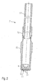
- the nozzle body 7 has in its discharge side of the Zumeßtechnisch 8 facing away from an in Fig. 2 illustrated annular seat member 4 and a subsequent injection in the injection direction injection hole insert 11 with at least one injection opening 14.
- the metering device 2 is fed via the lying at the top of the metering device 2 fuel port 13 fuel, such as gasoline, ethanol or methanol, by pressure from a fuel pump and fuel line, not shown.
- fuel such as gasoline, ethanol or methanol
- the fuel flows during operation of the metering device 1 down and is measured by the lying in the lower end of the metering device 2, not shown sealing seat in a known manner by opening and closing of the sealing seat in the supply line 8.
- opening air supply 9 can be supplied to the mixture preparation air or other gases, such as combustible residual gases from a reforming or fuel cell process.
- the fuel or the fuel-gas mixture flows through the supply line 8 to the nozzle body 7 and is there metered by the injection openings 14 shown in Fig. 2 in the Zumeßraum not shown.
- the Zumeß By Zumeßtechnisch 8, the Zumeß responded 2, in particular the opposite high temperatures and large temperature fluctuations sensitive, not shown sealing seat of the metering device 2, thermally decoupled from the temperatures in Zumeßraum not shown, which, for example, 500 ° C.
- the length, the material and the shape of Zumeß réelle 8 are chosen in particular according to the thermal and spatial conditions.
- the Zumeß réelle 8 may also have wall thickness-reduced points, which contribute to the thermal insulation or can act as a heat sink.
- Fig. 2 shows a schematic sectional view of the nozzle body 7 of the first embodiment.
- the nozzle body 7 consists of a carrier element 15, a feed tube 17 and a carrier member 15 and the feed tube 17 hydraulically sealing interconnecting intermediate element 16. All three components 15, 17, 16 are each hollow cylindrical and made of metal.
- the support member 15 includes with its the intermediate member 16 facing the end facing him the intermediate member 16.
- the intermediate member 16 is hydraulically sealed to the support member 15 and the feed tube 17 by pressing, soldering or welding, in particular laser welding.
- the connection can also be realized by a screw connection.
- the intermediate element 16 facing away from the injection-side end of the support member 15 is the annular seat member 4 and the spray-injection side arranged injection nozzle 11, which is formed in this embodiment as a spray orifice plate 12.
- the arrangement of carrier element 15, seat element 4 and spray perforated disc 12 is similar or corresponds to the discharge-side structure of a fuel injection valve as it is known from reciprocating internal combustion engines from the automotive field. However, the valve needle used there is missing with the valve closing body, which would form a sealing seat with the seat element 4 spray side.
- this arrangement cost can also be used as a nozzle body 7 in the present invention.
- the nozzle body 7 numerous already mass-produced, very available and therefore inexpensive spray perforated or stepped discs available. Due to the arrangement of the injection openings 14 in the injection or stepped disk, the emerging fuel cloud can advantageously be influenced in its shape and extent and acted upon by a twist.
Landscapes
- Chemical & Material Sciences (AREA)
- Engineering & Computer Science (AREA)
- Organic Chemistry (AREA)
- Chemical Kinetics & Catalysis (AREA)
- Combustion & Propulsion (AREA)
- Mechanical Engineering (AREA)
- General Engineering & Computer Science (AREA)
- Hydrogen, Water And Hydrids (AREA)
- Nozzles (AREA)
- Feeding, Discharge, Calcimining, Fusing, And Gas-Generation Devices (AREA)
Abstract
Claims (11)
- Installation de dosage (1) de carburants liquides notamment pour un réformeur chimique générant de l'hydrogène ou une installation de postcombustion dégageant de la chaleur, comprenant au moins une installation de distribution mesurée (2) pour distribuer de façon mesurée du carburant dans une conduite de dosage (8) et un corps de buse (7) relié à la conduite de distribution (8) qui comporte au moins un orifice d'éjection (14) débouchant dans une chambre de distribution mesurée,
caractérisée en ce que
le corps de buse (7) comporte un insert à orifices d'éjection (11) muni d'au moins un orifice d'éjection (14). - Installation de dosage selon la revendication 1,
caractérisée en ce que
l'insert à orifices d'éjection (11) est réalisé sous la forme d'un disque à orifices d'éjection (12). - Installation de dosage selon l'une des revendications 1 ou 2,
caractérisée en ce que
le corps de buse (7) est de forme tubulaire notamment de forme tubulaire cylindrique. - Installation de dosage selon l'une des revendications 2 ou 3,
caractérisée en ce que
le corps de buse (7) est formé d'un élément de support (15) tubulaire et d'un tube d'alimentation (17) tubulaire, ces deux éléments étant reliés de manière étanche du point de vue hydraulique, par un élément intermédiaire (16) tubulaire. - Installation de dosage selon la revendication 4,
caractérisée en ce que
du côté de l'éjection de l'élément de support tubulaire (15), il est prévu un élément formant siège (4), annulaire et l'insert à orifices d'éjection (11), situé en aval dans le sens de l'éjection, est muni d'orifices d'éjection (14). - Installation de dosage selon la revendication 5,
caractérisée en ce que
l'élément formant siège (4) et l'insert à orifices d'éjection (11) sont assemblés de manière étanche du point de vue hydraulique à la périphérie extérieure de l'élément de support (15) en particulier par compression ou soudage notamment soudage par laser. - Installation de dosage selon l'une des revendications précédentes,
caractérisée en ce que la conduite de distribution mesurée (8) et l'installation de distribution mesurée (2) sont assemblées de manière étanche hydrauliquement et de façon amovible par un adaptateur (6). - Installation de dosage selon la revendication 7,
caractérisée en ce que
l'adaptateur (8) comporte une conduite d'alimentation en air (9) qui communique avec la conduite de distribution mesurée, (8) dans l'adaptateur (6). - Installation de dosage selon l'une des revendications précédentes,
caractérisée en ce que
l'installation de distribution mesurée (2) est un injecteur de carburant. - Installation de dosage selon l'une des revendications précédentes,
caractérisée en ce que
l'injecteur de carburant est un injecteur basse pression, fonctionnant avec des pressions de combustion ou de carburant allant jusqu'à 10 bars. - Installation de dosage selon l'une des revendications précédentes,
caractérisée en ce que
la conduite de distribution mesurée (8) a, dans son tracé axial, au moins un point à épaisseur de paroi réduite ou une zone dont l'épaisseur de paroi est réduite.
Applications Claiming Priority (3)
| Application Number | Priority Date | Filing Date | Title |
|---|---|---|---|
| DE10251699A DE10251699A1 (de) | 2002-11-06 | 2002-11-06 | Dosiereinrichtung |
| DE10251699 | 2002-11-06 | ||
| PCT/DE2003/003070 WO2004041422A1 (fr) | 2002-11-06 | 2003-09-16 | Dispositif de dosage |
Publications (2)
| Publication Number | Publication Date |
|---|---|
| EP1560643A2 EP1560643A2 (fr) | 2005-08-10 |
| EP1560643B1 true EP1560643B1 (fr) | 2008-01-23 |
Family
ID=32239950
Family Applications (1)
| Application Number | Title | Priority Date | Filing Date |
|---|---|---|---|
| EP03769194A Expired - Lifetime EP1560643B1 (fr) | 2002-11-06 | 2003-09-16 | Dispositif de dosage |
Country Status (5)
| Country | Link |
|---|---|
| US (1) | US7300002B2 (fr) |
| EP (1) | EP1560643B1 (fr) |
| JP (1) | JP4388897B2 (fr) |
| DE (2) | DE10251699A1 (fr) |
| WO (1) | WO2004041422A1 (fr) |
Families Citing this family (9)
| Publication number | Priority date | Publication date | Assignee | Title |
|---|---|---|---|---|
| EP1559278B1 (fr) | 2002-10-18 | 2013-05-15 | Symbol Technologies, Inc. | Systeme et procede de minimisation d'une re-negotiation non voulue d'une tiquette passive d'identification de frequences radio |
| DE10314670A1 (de) * | 2003-04-01 | 2004-10-14 | Robert Bosch Gmbh | Verfahren zur Herstellung und Befestigung einer Lochscheibe |
| US7591950B2 (en) | 2004-11-02 | 2009-09-22 | Siemens Water Technologies Corp. | Submerged cross-flow filtration |
| KR100813244B1 (ko) * | 2006-07-11 | 2008-03-13 | 삼성에스디아이 주식회사 | 리포머 버너 |
| DE102007004799A1 (de) | 2007-01-31 | 2008-08-07 | Robert Bosch Gmbh | Dosiereinrichtung |
| JP5097652B2 (ja) * | 2008-09-05 | 2012-12-12 | 日立オートモティブシステムズ株式会社 | 燃料噴射弁及び2部品の結合方法 |
| DE102008055098B4 (de) | 2008-12-22 | 2019-10-02 | Robert Bosch Gmbh | Gaseinblasventil |
| US20120137695A1 (en) * | 2010-12-01 | 2012-06-07 | General Electric Company | Fuel nozzle with gas only insert |
| CN106299407B (zh) * | 2016-11-08 | 2018-12-25 | 常州博能新能源有限公司 | 一种自计量的甲醇燃料电池液体供给装置 |
Citations (2)
| Publication number | Priority date | Publication date | Assignee | Title |
|---|---|---|---|---|
| WO2004036119A1 (fr) * | 2002-10-14 | 2004-04-29 | Robert Bosch Gmbh | Buse d'injection |
| WO2004035467A1 (fr) * | 2002-10-14 | 2004-04-29 | Robert Bosch Gmbh | Buse d'injection |
Family Cites Families (9)
| Publication number | Priority date | Publication date | Assignee | Title |
|---|---|---|---|---|
| US3362647A (en) * | 1965-11-03 | 1968-01-09 | Gulf Research Development Co | Oil burner spray nozzle |
| GB1286851A (en) * | 1969-06-27 | 1972-08-23 | Petrol Injection Ltd | Fuel injection systems |
| US3971847A (en) | 1973-12-26 | 1976-07-27 | The United States Of America As Represented By The Adminstrator Of The National Aeronautics And Space Administration | Hydrogen-rich gas generator |
| US5190216A (en) * | 1991-04-19 | 1993-03-02 | Deneke Carl F | Fuel-injection apparatus for internal combustion engines |
| US5484108A (en) * | 1994-03-31 | 1996-01-16 | Siemens Automotive L.P. | Fuel injector having novel multiple orifice disk members |
| US5544816A (en) * | 1994-08-18 | 1996-08-13 | Siemens Automotive L.P. | Housing for coil of solenoid-operated fuel injector |
| JP3750126B2 (ja) * | 1996-03-26 | 2006-03-01 | 株式会社デンソー | 燃料噴射弁 |
| DE10057631A1 (de) * | 2000-11-21 | 2002-05-23 | Bosch Gmbh Robert | Brennstoffeinspritzventil |
| JP2003232268A (ja) * | 2002-02-08 | 2003-08-22 | Hitachi Ltd | 電磁式燃料噴射弁 |
-
2002
- 2002-11-06 DE DE10251699A patent/DE10251699A1/de not_active Withdrawn
-
2003
- 2003-09-16 EP EP03769194A patent/EP1560643B1/fr not_active Expired - Lifetime
- 2003-09-16 WO PCT/DE2003/003070 patent/WO2004041422A1/fr not_active Ceased
- 2003-09-16 US US10/514,994 patent/US7300002B2/en not_active Expired - Fee Related
- 2003-09-16 DE DE50309094T patent/DE50309094D1/de not_active Expired - Lifetime
- 2003-09-16 JP JP2004549048A patent/JP4388897B2/ja not_active Expired - Lifetime
Patent Citations (2)
| Publication number | Priority date | Publication date | Assignee | Title |
|---|---|---|---|---|
| WO2004036119A1 (fr) * | 2002-10-14 | 2004-04-29 | Robert Bosch Gmbh | Buse d'injection |
| WO2004035467A1 (fr) * | 2002-10-14 | 2004-04-29 | Robert Bosch Gmbh | Buse d'injection |
Also Published As
| Publication number | Publication date |
|---|---|
| JP2006504611A (ja) | 2006-02-09 |
| US7300002B2 (en) | 2007-11-27 |
| JP4388897B2 (ja) | 2009-12-24 |
| WO2004041422A1 (fr) | 2004-05-21 |
| EP1560643A2 (fr) | 2005-08-10 |
| DE50309094D1 (de) | 2008-03-13 |
| DE10251699A1 (de) | 2004-06-03 |
| WO2004041422A8 (fr) | 2004-07-22 |
| US20050161526A1 (en) | 2005-07-28 |
Similar Documents
| Publication | Publication Date | Title |
|---|---|---|
| EP1252679B1 (fr) | Dispositif de pulverisation | |
| EP1339965B1 (fr) | Systeme d'injection permettant d'injecter deux liquides dans une chambre de reaction de maniere dosee | |
| EP1560644B1 (fr) | Dispositif de dosage | |
| EP1567253B1 (fr) | Dispositif d'atomisation | |
| EP1560645B1 (fr) | Dispositif de dosage | |
| EP1560643A2 (fr) | Dispositif de dosage | |
| EP1520315B1 (fr) | Dispositif atomiseur | |
| EP2117695A1 (fr) | Dispositif de dosage | |
| WO2004035467A1 (fr) | Buse d'injection | |
| WO2004036119A1 (fr) | Buse d'injection | |
| EP1578535B1 (fr) | Dispositif de dosage chauffe pour le reformeur d'un dispositif de piles a combustible | |
| DE102019001163A1 (de) | Verbrennungsmotor mit Vorkammerzündung | |
| DE19956378B4 (de) | Verfahren zum Einbringen von verschiedenen gasförmigen und/oder flüssigen Betriebsstoffen in einen Reaktionsraum | |
| EP1752633B1 (fr) | Appareil pour la génération de gaz chaud dans un système d'échappement d'un moteur thermique | |
| DE102020128707B3 (de) | Fluidleitvorrichtung mit einem Fluidleitkörper | |
| EP1408225B1 (fr) | Adaptateur pour vaporisateur | |
| DE10229904A1 (de) | Dosiereinrichtung | |
| EP1408226A2 (fr) | Ensemble de pulvérisation | |
| EP1418333B1 (fr) | Vaporisateur |
Legal Events
| Date | Code | Title | Description |
|---|---|---|---|
| PUAI | Public reference made under article 153(3) epc to a published international application that has entered the european phase |
Free format text: ORIGINAL CODE: 0009012 |
|
| 17P | Request for examination filed |
Effective date: 20050606 |
|
| AK | Designated contracting states |
Kind code of ref document: A2 Designated state(s): AT BE BG CH CY CZ DE DK EE ES FI FR GB GR HU IE IT LI LU MC NL PT RO SE SI SK TR |
|
| AX | Request for extension of the european patent |
Extension state: AL LT LV MK |
|
| DAX | Request for extension of the european patent (deleted) | ||
| RBV | Designated contracting states (corrected) |
Designated state(s): DE FR IT |
|
| GRAP | Despatch of communication of intention to grant a patent |
Free format text: ORIGINAL CODE: EPIDOSNIGR1 |
|
| GRAS | Grant fee paid |
Free format text: ORIGINAL CODE: EPIDOSNIGR3 |
|
| GRAA | (expected) grant |
Free format text: ORIGINAL CODE: 0009210 |
|
| AK | Designated contracting states |
Kind code of ref document: B1 Designated state(s): DE FR IT |
|
| REF | Corresponds to: |
Ref document number: 50309094 Country of ref document: DE Date of ref document: 20080313 Kind code of ref document: P |
|
| ET | Fr: translation filed | ||
| PLBE | No opposition filed within time limit |
Free format text: ORIGINAL CODE: 0009261 |
|
| STAA | Information on the status of an ep patent application or granted ep patent |
Free format text: STATUS: NO OPPOSITION FILED WITHIN TIME LIMIT |
|
| 26N | No opposition filed |
Effective date: 20081024 |
|
| PGFP | Annual fee paid to national office [announced via postgrant information from national office to epo] |
Ref country code: IT Payment date: 20090926 Year of fee payment: 7 |
|
| PG25 | Lapsed in a contracting state [announced via postgrant information from national office to epo] |
Ref country code: IT Free format text: LAPSE BECAUSE OF NON-PAYMENT OF DUE FEES Effective date: 20100916 |
|
| REG | Reference to a national code |
Ref country code: FR Ref legal event code: ST Effective date: 20110531 |
|
| PG25 | Lapsed in a contracting state [announced via postgrant information from national office to epo] |
Ref country code: FR Free format text: LAPSE BECAUSE OF NON-PAYMENT OF DUE FEES Effective date: 20100930 |
|
| PGFP | Annual fee paid to national office [announced via postgrant information from national office to epo] |
Ref country code: FR Payment date: 20091005 Year of fee payment: 7 |
|
| PGFP | Annual fee paid to national office [announced via postgrant information from national office to epo] |
Ref country code: DE Payment date: 20121122 Year of fee payment: 10 |
|
| REG | Reference to a national code |
Ref country code: DE Ref legal event code: R119 Ref document number: 50309094 Country of ref document: DE Effective date: 20140401 |
|
| PG25 | Lapsed in a contracting state [announced via postgrant information from national office to epo] |
Ref country code: DE Free format text: LAPSE BECAUSE OF NON-PAYMENT OF DUE FEES Effective date: 20140401 |