EP1560256A2 - Elektrodenloses Beleuchtungssystem - Google Patents
Elektrodenloses Beleuchtungssystem Download PDFInfo
- Publication number
- EP1560256A2 EP1560256A2 EP04104561A EP04104561A EP1560256A2 EP 1560256 A2 EP1560256 A2 EP 1560256A2 EP 04104561 A EP04104561 A EP 04104561A EP 04104561 A EP04104561 A EP 04104561A EP 1560256 A2 EP1560256 A2 EP 1560256A2
- Authority
- EP
- European Patent Office
- Prior art keywords
- resonator
- bulb
- control member
- resonance control
- microwave
- Prior art date
- Legal status (The legal status is an assumption and is not a legal conclusion. Google has not performed a legal analysis and makes no representation as to the accuracy of the status listed.)
- Withdrawn
Links
Images

Classifications
-
- H—ELECTRICITY
- H01—ELECTRIC ELEMENTS
- H01J—ELECTRIC DISCHARGE TUBES OR DISCHARGE LAMPS
- H01J65/00—Lamps without any electrode inside the vessel; Lamps with at least one main electrode outside the vessel
- H01J65/04—Lamps in which a gas filling is excited to luminesce by an external electromagnetic field or by external corpuscular radiation, e.g. for indicating plasma display panels
- H01J65/042—Lamps in which a gas filling is excited to luminesce by an external electromagnetic field or by external corpuscular radiation, e.g. for indicating plasma display panels by an external electromagnetic field
- H01J65/044—Lamps in which a gas filling is excited to luminesce by an external electromagnetic field or by external corpuscular radiation, e.g. for indicating plasma display panels by an external electromagnetic field the field being produced by a separate microwave unit
Definitions
- the present invention relates to an electrodeless lighting system, and more particularly, to an electrode less lighting system capable of facilitating light distribution for achieving lateral lighting and a wider range of lighting and simultaneously improving lighting efficiency.
- an electrodeless lighting system using microwaves is a device for emitting visible light and ultraviolet light upon applying microwave energy to an electrodeless plasma bulb.
- the electrodeless lighting system has a longer life span than that of incandescent lamp or fluorescent lamp which is generally used, and has higher lighting effect
- Figure 1 is a sectional view showing a structure of a conventional electrodeless lighting system.
- a high voltage generating unit 2 for raising a common AC voltage to a high voltage is installed at one side in a case 1, and a magnetron 3 for generating microwave by a high voltage supplied from the high voltage generating unit 2 is installed at the other side of the case 1.
- a wave guide 4 is installed inside of the case 1 and communicates with an output portion 3a of the magnetron so that microwave generated by the magnetron 3 passes through the wave guide 4.
- An exit 4a of the wave guide 4 is exposed out of the case 1 through an aperture of the case 1.
- a rotary shaft 5 is rotatably coupled at a shaft hole 4a formed at a central portion of the wave guide 4 in a vertical direction.
- a bulb 7 filled with a material which emits light by microwave energy is installed at an upper end portion of the rotary shaft 5 protruding outwardly through the exit 4a of the wave guide 4.
- a bulb rotating motor 8 having a motor shaft 8 connected to the rotary shaft 5 in the wave guide 4 by a connection pipe 7 is installed at a lower end portion of the rotary shaft 5 outside the wave guide 4 in order to rotate the rotary shaft.
- a mesh-structured resonator 9 having a predetermined height (H) is coupled to the exit 4a of the wave guide 4, which is positioned outside the case 1, encompassing the bulb 6.
- the resonator 9 blocks leakage of electromagnetic waves introduced through the wave guide 4 and simultaneously passes light emitted from the bulb 6.
- a reflector 10 is fixed around the resonator 9 to cover the outer side of the resonator 9 in order to reflect light which has passed through the resonator 9 after generated in the bulb 6.
- the resonator 9 is designed to use a TE mode (Transverse Electric mode). Because only one basic mode is used, intensity of an electric field is strongest at a central portion of the resonator 9. Accordingly, the bulb 6 is installed at a central portion (h) of the resonator, where the intensity of the electric field is strongest.
- TE mode Transverse Electric mode
- a cooling fan assembly 14 including a fan motor 11, a cooling fan 12 and a fan housing 13 having an outlet13a is installed at a lower side of the case 1 so as to cool the magnetron 3 and the high voltage generating unit 2.
- an inlet 13b through which external air is sucked by rotation of the cooling fan 12 is formed at the fan housing 13.
- a plurality of discharge openings 1b are formed at an edge of an upper surface of the case 1 so that the air sucked through the inlet 13b can be discharged outside by way of the high voltage generating unit 2 and the magnetron 3.
- Non-described reference numeral 15 in the drawing is a dielectric mirror.
- the generated microwave is radiated into the resonator 9 through the wave guide 4, a material within the bulb 6 is electrically discharged by the radiated microwave to thereby generate light by plasma, and the generated light is thrown to the front by being reflected by the dielectric mirror 14 and the reflector 10.
- the bulb rotating motor 8 rotates the rotary shaft 5 so that a temperature of the bulb 6, which is raised by the light generated in the bulb 6, does not exceed a predetermined temperature
- the fan motor 11 installed at a lower portion inside the case 1 rotates to rotate the cooling fan 12.
- External air sucked through the inlet 13b by the rotation of the cooling fan 12 flows through the outlet 13a, cools the high voltage generating unit 2 and the magnetron 3, and then is discharged outside the case 1 through the discharge opening 1 b formed at the upper surface of the case 1.
- a distance (h) between a central portion of the bulb 6 and the dielectric mirror 15 is to be designed to be longer.
- a height (H) of the resonator should be designed to be longer, and, if the size of the resonator 9 becomes great in such a manner, a higher mode has to be used. If the higher mode is used, a loss of the microwave becomes great in the basic mode, thereby causing not only a size increase of the entire electrode lighting system but also remarkable deterioration in lighting efficiency. Accordingly, the conventional electrodeless lighting system has a problem in that light distribution for achieving lateral lighting and wide-area lighting is difficult.
- an object of the present invention is to provide an electrodeless lighting system capable of facilitating light distribution for achieving lateral lighting and a wide range of lighting and simultaneously improving lighting efficiency.
- an electrode less lighting system comprising: a resonator which is installed at an exit of a wave guide for guiding microwave generated in a magnetron and making light pass and microwave resonate therein; a bulb positioned in the resonator and having a luminous portion filled with a luminous material which emits light by the microwave energy and a shaft portion integrally extended from the luminous portion; a resonance control member disposed inside the resonator and having a height controlled according to a position of the luminous portion of the bulb and the entire length of the resonator so as to made optimum resonance of the microwave; and a reflector positioned around the resonator for reflecting light emitted from the bulb.
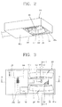
- Figure 2 is a perspective view showing a plasma lamp system in accordance with one embodiment of the present invention
- Figure 3 is a bottom view of Figure 2
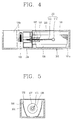
- Figure 4 is a sectional view taken along line IV-IV of Figure 3
- Figure 5 is a sectional view taken along line V-V of Figure 3
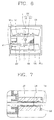
- Figure 6 is a bottom view showing a main part of an electrode less lighting system in accordance with one embodiment of the present invention.
- a plasma lamp system in accordance with the present invention includes a case 101, a high voltage generating unit 102, a magnetron 103, a wave guide 104, a bulb 105, a resonator 106, a resonance control member 107 and a reflector 108.
- the case 101 includes an opening 101 a formed as one portion of one surface of the case 101 is opened; and a machine chamber 101 b formed adjacent to the opening 101a, in which the magnetron 103, the high voltage generating unit 102 and the wave guide 104 are positioned.
- the high voltage generating unit 102 is fixed at one side in the machine chamber 101b, generates a high voltage when a common AC voltage is applied thereto, and supplies the generated high voltage to the magnetron 103.
- the magnetron 103 is installed at the other side of the machine chamber 101b, and converts electrical energy into high frequency energy such as microwave when a high voltage is inputted from the high voltage generating unit 102.
- the converted high voltage energy is outputted to the wave guide 104 through an antenna (not shown) insertedly fixed in the wave guide 104 installed at one side of the magnetron 103.
- the wave guide 104 guides the microwave outputted from the magnetron 103 into the resonator 106.
- the resonator 106 is installed at an exit 104a of the wave guide 104 for guiding microwave generated from the magnetron 103 and makes light pass and microwave resonate therein. More detail, the resonator 106 is installed at the opening 101 a to cover the bulb 106, and one side of the resonator 106 is coupled to an outer circumferential surface of an exit 104a of the wave guide 104.
- the resonator 106 has a netlike metallic body and is formed in a cylindrical shape, and a cross-section of the resonator 106 is preferably formed in a circular shape or a polygonal shape.
- the resonator 106 is preferably filled with a dielectric material.
- the bulb 105 includes a spherical luminous portion 111 having a predetermined internal volume and filled with a luminous material which emits light by the microwave energy, and a shaft portion 112 integrally extended from the luminous portion 111.
- the luminous portion 111 is disposed inside the resonator 106, and the shaft portion 112 is penetratingly installed to pass through the central portion of the wave guide 104.
- the shaft portion 112 is connected to a motor shaft (not shown) of a bulb rotating motor 113 installed in the machine chamber 101 b of the case 101 to thereby be rotated at a predetermined speed.
- the luminous portion 111 is preferably made of a material having high light transmittance and low dielectric loss, such as quartz.
- a material within the luminous portion 111 is constituted by a luminous material such as metal, halogen compounds, sulfur or selenium for leading light-emission by forming plasma, inert gas such as argon, xenon, kripton for forming plasma inside the bulb 106 at an initial stage of emitting light, and additives for making the lighting to be easy by helping the initial discharge or for controlling spectrum of the emitted light.
- the resonance control member 107 is disposed inside the resonator 106 and has a through hole therein; the shaft portion 112 of the bulb 105 is rotatably installed in the through hole of the resonance control member 107.
- a height (h') of the resonance control member 107 is controlled according to the position of the luminous portion 111 of the bulb 105 and the entire length (L") of the resonator 106 so that optimum resonance is generated inside the resonator 106.
- the luminous portion 111 of the bulb 105 is centrally located between one outer end of the resonance control member 107 and one inner end of the resonator 106.
- an interval (L') between one inner wall 101 c of the opening 101 a and the luminous portion 111 of the bulb 105 is longer than that of the conventional electrodeless lighting system.
- the entire length (L") of the resonator 106 is designed to be longer.
- the resonance control member 107 is installed to control a resonant interval (L) between one inner end of the resonance control member and one outer end of the resonator 106, so that resonance of electromagnetic waves is generated in a basic mode.
- the resonance control member 107 is made of a metal material, and is formed in a cylindrical shape like the shape of the resonator 106. In addition, its cross section is preferably formed in a circular shape or in a polygonal shape.
- a ring-shaped stub 121 for impedance matching is integrally formed at one end of the resonance control member 107.
- dielectric coating or metallic coating is preferably performed on an outside of the resonant control member 107, so that resonant efficiency of microwave in the resonator 106 is improved.
- a bearing 120 for smooth rotation of the shaft portion 112 is mounted at an inner circumferential surface of the through hole of the resonance control member 107, which comes in contact with the shaft portion 112 of the bulb 105.
- the reflector 108 is a metallic plate body.
- a pair of reflectors 108 are installed at the opening 101 a of the case 101 at a predetermined interval, and reflect light emitted from the luminous portion 111 of the bulb 105 to thereby allow the light to be laterally thrown through the opening 101a.
- the reflector 108 preferably has a predetermined radius of curvature in order to efficiently reflect light.
- Non-described reference numeral 132 is a lamp cover.
- a high voltage generated in a high voltage generating unit 102 is inputted to a magnetron 103, microwave having high frequency energy is generated in the magnetron 103, and the generated microwave is outputted through an antenna.
- the outputted microwave is guided into a resonator 106 by way of a wave guide 104, and an optimum resonant frequency is selected in the resonator 106.
- the microwave in the selected resonant frequency band resonates in a resonant space of the resonator 106, forming a strong electric field at a luminous portion 111 of a bulb 105.
- Inert gas within the luminous portion 111 is electrically discharged by the formed electric field, and heat generated during said electric discharge gasifies a luminous material, forming plasma.
- the plasma maintains the electric-discharge by the microwave, thereby emitting light of high intensity.
- the light is reflected by a reflector 108, thereby performing lighting through the opening 101a.
- the entire length (L") of the resonator 106 is designed to be long.
- a resonant interval (L) in the resonator 106 is determined according to a controlled height (h') of the resonance control member 107 so that resonance of the microwave can be generated in a basic mode.
- the luminous portion 111 of the bulb 105 is positioned at a central portion of the resonant interval (L), where the intensity of an electric field is strongest.
- the reflector 108 for reflecting light emitted in the luminous portion 11 is disposed at a rear of the luminous portion 111, thereby achieving lateral lighting and a wider range of lighting.
- a resonant interval in a resonator is easily controlled by the resonance control member, a strong electric field can be formed at a luminous portion sufficiently just in a basic mode without microwave loss in the basic mode due to a use of a higher mode even if an interval between an exit of a wave guide, one inner wall of an opening of a case, and the luminous portion of the bulb is lengthened, and thus the size of the resonator becomes great.
- the size and the disposition of a reflector can be more freely designed, thereby easily achieving lateral lighting and a wider range of lighting.
- efficient lighting can be made when the present electrodeless lighting system is used for a lighting device such as a street lamp which performs lateral lighting.
Landscapes
- Physics & Mathematics (AREA)
- Engineering & Computer Science (AREA)
- Plasma & Fusion (AREA)
- Electromagnetism (AREA)
- Non-Portable Lighting Devices Or Systems Thereof (AREA)
- Discharge Lamps And Accessories Thereof (AREA)
- Circuit Arrangements For Discharge Lamps (AREA)
Applications Claiming Priority (2)
| Application Number | Priority Date | Filing Date | Title |
|---|---|---|---|
| KR1020030090972A KR100575666B1 (ko) | 2003-12-13 | 2003-12-13 | 플라즈마 램프 시스템 |
| KR2003090972 | 2003-12-13 |
Publications (2)
| Publication Number | Publication Date |
|---|---|
| EP1560256A2 true EP1560256A2 (de) | 2005-08-03 |
| EP1560256A3 EP1560256A3 (de) | 2006-11-22 |
Family
ID=34651439
Family Applications (1)
| Application Number | Title | Priority Date | Filing Date |
|---|---|---|---|
| EP04104561A Withdrawn EP1560256A3 (de) | 2003-12-13 | 2004-09-21 | Elektrodenloses Beleuchtungssystem |
Country Status (5)
| Country | Link |
|---|---|
| US (1) | US7276860B2 (de) |
| EP (1) | EP1560256A3 (de) |
| JP (1) | JP4091596B2 (de) |
| KR (1) | KR100575666B1 (de) |
| CN (1) | CN100409399C (de) |
Cited By (1)
| Publication number | Priority date | Publication date | Assignee | Title |
|---|---|---|---|---|
| EP3208827A4 (de) * | 2014-10-14 | 2018-07-04 | NovStream LLC | Plasmabeleuchtungsvorrichtung mit mikrowellenpumpe |
Families Citing this family (24)
| Publication number | Priority date | Publication date | Assignee | Title |
|---|---|---|---|---|
| KR100631541B1 (ko) * | 2004-10-26 | 2006-10-09 | 엘지전자 주식회사 | 플라즈마를 이용한 가로등 시스템 |
| KR100677277B1 (ko) * | 2005-05-11 | 2007-02-02 | 엘지전자 주식회사 | 무전극 램프 시스템 |
| KR100748529B1 (ko) | 2005-09-23 | 2007-08-13 | 엘지전자 주식회사 | 무전극 조명기기의 고온 운전형 무전극 전구 및 이를구비한 무전극 조명기기 |
| KR100761264B1 (ko) * | 2005-09-28 | 2007-09-28 | 엘지전자 주식회사 | 알루미늄 공진기를 구비한 무전극 조명기기 |
| KR20070035888A (ko) * | 2005-09-28 | 2007-04-02 | 엘지전자 주식회사 | 이종 개구률부를 구비한 무전극 조명기기의 공진기 |
| KR20070039304A (ko) * | 2005-10-07 | 2007-04-11 | 엘지전자 주식회사 | 초기 점등 수단을 구비한 중출력 무전극 조명기기 |
| KR100789300B1 (ko) * | 2006-02-14 | 2007-12-28 | 엘지전자 주식회사 | 무전극 조명기기용 공진기 |
| KR101271226B1 (ko) * | 2006-02-16 | 2013-06-03 | 삼성디스플레이 주식회사 | 백라이트 유닛 및 이를 포함하는 액정 표시 장치 |
| JP4757664B2 (ja) * | 2006-03-07 | 2011-08-24 | スタンレー電気株式会社 | マイクロ波供給源装置 |
| KR100831210B1 (ko) * | 2006-09-14 | 2008-05-21 | 엘지전자 주식회사 | 무전극 조명기기가 적용된 가로등 |
| KR100867625B1 (ko) * | 2007-03-30 | 2008-11-10 | 엘지전자 주식회사 | 가로등용 무전극 조명기기 |
| US8179047B2 (en) * | 2008-11-24 | 2012-05-15 | Topanga Technologies, Inc. | Method and system for adjusting the frequency of a resonator assembly for a plasma lamp |
| KR101031107B1 (ko) * | 2008-11-25 | 2011-04-26 | 한국전기연구원 | 진동체를 이용한 가변 길이 마이크로파 반응기 및 그 방법 |
| DE102009018840A1 (de) * | 2009-04-28 | 2010-11-25 | Auer Lighting Gmbh | Plasmalampe |
| US8256938B2 (en) * | 2009-06-15 | 2012-09-04 | Topanga Technologies, Inc. | Method and system for converting a sodium street lamp to an efficient white light source |
| JP2011049026A (ja) * | 2009-08-27 | 2011-03-10 | Iwasaki Electric Co Ltd | 光源装置 |
| WO2011119452A1 (en) * | 2010-03-22 | 2011-09-29 | Robe Lighting Inc | Plasma light source automated luminaire |
| US9839083B2 (en) | 2011-06-03 | 2017-12-05 | Cree, Inc. | Solid state lighting apparatus and circuits including LED segments configured for targeted spectral power distribution and methods of operating the same |
| US8742671B2 (en) | 2011-07-28 | 2014-06-03 | Cree, Inc. | Solid state lighting apparatus and methods using integrated driver circuitry |
| US9613792B2 (en) * | 2013-03-15 | 2017-04-04 | Heraeus Noblelight America Llc | Multi-spectral electrodeless ultraviolet light source, lamp module, and lamp system |
| KR101479021B1 (ko) * | 2013-05-13 | 2015-01-05 | 위아코퍼레이션 주식회사 | 마이크로웨이브를 이용한 무전극 광원장치 |
| US9726360B1 (en) | 2014-09-25 | 2017-08-08 | CSC Holdings, LLC | Luminaires having a wireless antenna |
| KR102675524B1 (ko) * | 2023-06-21 | 2024-06-17 | 웨이브기어 주식회사 | 플라즈마 조명 장치 |
| KR102689971B1 (ko) * | 2023-06-21 | 2024-08-05 | 웨이브기어 주식회사 | 플라즈마 조명 장치 |
Family Cites Families (18)
| Publication number | Priority date | Publication date | Assignee | Title |
|---|---|---|---|---|
| US57842A (en) * | 1866-09-11 | Improvement in wheat-drills | ||
| US135322A (en) * | 1873-01-28 | Improvement in ivlusic-leaf turners | ||
| US4388601A (en) * | 1981-09-30 | 1983-06-14 | Varian Associates, Inc. | Symmetrizing means for RF coils in a microwave cavity |
| CN2181620Y (zh) * | 1993-12-30 | 1994-11-02 | 朱彦丰 | 矿用电子节能灯 |
| US5525865A (en) * | 1994-02-25 | 1996-06-11 | Fusion Lighting, Inc. | Compact microwave source for exciting electrodeless lamps |
| JP3209952B2 (ja) | 1996-11-01 | 2001-09-17 | 松下電器産業株式会社 | 高周波無電極放電ランプ装置 |
| JP2001266803A (ja) | 2000-03-17 | 2001-09-28 | Victor Co Of Japan Ltd | 無電極放電ランプ |
| US6724146B2 (en) * | 2001-11-27 | 2004-04-20 | Raytheon Company | Phased array source of electromagnetic radiation |
| JP3400796B2 (ja) | 2000-10-30 | 2003-04-28 | 松下電器産業株式会社 | 無電極放電ランプ装置 |
| US6737810B2 (en) * | 2000-10-30 | 2004-05-18 | Matsushita Electric Industrial Co., Ltd. | Electrodeless discharge lamp apparatus with adjustable exciting electrodes |
| KR100724371B1 (ko) | 2000-12-27 | 2007-06-04 | 엘지전자 주식회사 | 마이크로파를 이용한 조명 장치 |
| JP2003022785A (ja) | 2001-07-09 | 2003-01-24 | Matsushita Electric Works Ltd | マイクロ波無電極放電灯装置 |
| JP3927387B2 (ja) * | 2001-08-29 | 2007-06-06 | 株式会社オーク製作所 | 無電極ランプシステム |
| KR100393817B1 (ko) * | 2001-09-27 | 2003-08-02 | 엘지전자 주식회사 | 무전극 조명기기 |
| KR100393816B1 (ko) * | 2001-09-27 | 2003-08-02 | 엘지전자 주식회사 | 마이크로파를 이용한 무전극 방전 램프 장치 |
| KR100430006B1 (ko) * | 2002-04-10 | 2004-05-03 | 엘지전자 주식회사 | 무전극 조명 시스템 |
| KR100531804B1 (ko) * | 2002-12-17 | 2005-12-02 | 엘지전자 주식회사 | 무전극 조명 시스템 |
| KR100556782B1 (ko) * | 2003-12-06 | 2006-03-10 | 엘지전자 주식회사 | 플라즈마 램프 시스템 |
-
2003
- 2003-12-13 KR KR1020030090972A patent/KR100575666B1/ko not_active Expired - Fee Related
-
2004
- 2004-09-21 EP EP04104561A patent/EP1560256A3/de not_active Withdrawn
- 2004-09-28 US US10/950,463 patent/US7276860B2/en not_active Expired - Fee Related
- 2004-10-19 CN CNB2004100841997A patent/CN100409399C/zh not_active Expired - Fee Related
- 2004-12-10 JP JP2004357988A patent/JP4091596B2/ja not_active Expired - Fee Related
Cited By (1)
| Publication number | Priority date | Publication date | Assignee | Title |
|---|---|---|---|---|
| EP3208827A4 (de) * | 2014-10-14 | 2018-07-04 | NovStream LLC | Plasmabeleuchtungsvorrichtung mit mikrowellenpumpe |
Also Published As
| Publication number | Publication date |
|---|---|
| EP1560256A3 (de) | 2006-11-22 |
| US7276860B2 (en) | 2007-10-02 |
| JP4091596B2 (ja) | 2008-05-28 |
| JP2005174938A (ja) | 2005-06-30 |
| KR100575666B1 (ko) | 2006-05-03 |
| CN100409399C (zh) | 2008-08-06 |
| KR20050058941A (ko) | 2005-06-17 |
| US20050128750A1 (en) | 2005-06-16 |
| CN1627473A (zh) | 2005-06-15 |
Similar Documents
| Publication | Publication Date | Title |
|---|---|---|
| US7276860B2 (en) | Electrodeless lighting system | |
| KR100556782B1 (ko) | 플라즈마 램프 시스템 | |
| JP4170681B2 (ja) | マイクロ波を利用した無電極放電ランプ | |
| KR100393817B1 (ko) | 무전극 조명기기 | |
| CN100356504C (zh) | 无电极照明系统 | |
| EP1703543A2 (de) | Elektrodenloses Beleuchtungssystem | |
| KR100901383B1 (ko) | 도파관 및 이를 구비한 무전극 조명장치 | |
| US7126282B2 (en) | Electrodeless lighting system | |
| KR100565217B1 (ko) | 무전극 조명기기의 도파관구조 | |
| KR100608881B1 (ko) | 무전극 조명기기의 초기점등장치 | |
| EP1684330A1 (de) | Elektrodenloses Beleuchtungssystem mit mittlerer Ausgangsleistung | |
| KR100531905B1 (ko) | 무전극 조명기기의 전구구조 | |
| KR100724383B1 (ko) | 무전극 조명기기 | |
| KR100396770B1 (ko) | 마그네트론 일체형 마이크로파 조명 장치 | |
| KR100459468B1 (ko) | 무전극 조명기기용 도파관의 구조 | |
| KR100739161B1 (ko) | 전구 편심형 무전극 조명기기 | |
| KR100400401B1 (ko) | 무전극 조명기기의 램프 방열구조 | |
| US7446484B2 (en) | Middle output electrodeless lighting system | |
| KR100393788B1 (ko) | 마이크로파를 이용한 조명장치 및 도파관 구조 | |
| KR20070117386A (ko) | 마이크로파를 이용한 조명기기 및 그의 공진기 |
Legal Events
| Date | Code | Title | Description |
|---|---|---|---|
| PUAI | Public reference made under article 153(3) epc to a published international application that has entered the european phase |
Free format text: ORIGINAL CODE: 0009012 |
|
| 17P | Request for examination filed |
Effective date: 20040921 |
|
| AK | Designated contracting states |
Kind code of ref document: A2 Designated state(s): AT BE BG CH CY CZ DE DK EE ES FI FR GB GR HU IE IT LI LU MC NL PL PT RO SE SI SK TR |
|
| AX | Request for extension of the european patent |
Extension state: AL HR LT LV MK |
|
| PUAL | Search report despatched |
Free format text: ORIGINAL CODE: 0009013 |
|
| AK | Designated contracting states |
Kind code of ref document: A3 Designated state(s): AT BE BG CH CY CZ DE DK EE ES FI FR GB GR HU IE IT LI LU MC NL PL PT RO SE SI SK TR |
|
| AX | Request for extension of the european patent |
Extension state: AL HR LT LV MK |
|
| AKX | Designation fees paid |
Designated state(s): DE GB IT |
|
| STAA | Information on the status of an ep patent application or granted ep patent |
Free format text: STATUS: THE APPLICATION IS DEEMED TO BE WITHDRAWN |
|
| 18D | Application deemed to be withdrawn |
Effective date: 20110401 |