EP1559948A2 - Dispositif de pivotement pour dispositif d'affichage à cristaux liquides - Google Patents
Dispositif de pivotement pour dispositif d'affichage à cristaux liquides Download PDFInfo
- Publication number
- EP1559948A2 EP1559948A2 EP05001598A EP05001598A EP1559948A2 EP 1559948 A2 EP1559948 A2 EP 1559948A2 EP 05001598 A EP05001598 A EP 05001598A EP 05001598 A EP05001598 A EP 05001598A EP 1559948 A2 EP1559948 A2 EP 1559948A2
- Authority
- EP
- European Patent Office
- Prior art keywords
- lcd
- slider
- mounting recess
- rotating apparatus
- guide rail
- Prior art date
- Legal status (The legal status is an assumption and is not a legal conclusion. Google has not performed a legal analysis and makes no representation as to the accuracy of the status listed.)
- Withdrawn
Links
Images


Classifications
-
- F—MECHANICAL ENGINEERING; LIGHTING; HEATING; WEAPONS; BLASTING
- F16—ENGINEERING ELEMENTS AND UNITS; GENERAL MEASURES FOR PRODUCING AND MAINTAINING EFFECTIVE FUNCTIONING OF MACHINES OR INSTALLATIONS; THERMAL INSULATION IN GENERAL
- F16M—FRAMES, CASINGS OR BEDS OF ENGINES, MACHINES OR APPARATUS, NOT SPECIFIC TO ENGINES, MACHINES OR APPARATUS PROVIDED FOR ELSEWHERE; STANDS; SUPPORTS
- F16M11/00—Stands or trestles as supports for apparatus or articles placed thereon Stands for scientific apparatus such as gravitational force meters
- F16M11/02—Heads
- F16M11/04—Means for attachment of apparatus; Means allowing adjustment of the apparatus relatively to the stand
- F16M11/06—Means for attachment of apparatus; Means allowing adjustment of the apparatus relatively to the stand allowing pivoting
- F16M11/10—Means for attachment of apparatus; Means allowing adjustment of the apparatus relatively to the stand allowing pivoting around a horizontal axis
-
- B—PERFORMING OPERATIONS; TRANSPORTING
- B60—VEHICLES IN GENERAL
- B60P—VEHICLES ADAPTED FOR LOAD TRANSPORTATION OR TO TRANSPORT, TO CARRY, OR TO COMPRISE SPECIAL LOADS OR OBJECTS
- B60P7/00—Securing or covering of load on vehicles
- B60P7/02—Covering of load
-
- B—PERFORMING OPERATIONS; TRANSPORTING
- B60—VEHICLES IN GENERAL
- B60Y—INDEXING SCHEME RELATING TO ASPECTS CROSS-CUTTING VEHICLE TECHNOLOGY
- B60Y2200/00—Type of vehicle
- B60Y2200/10—Road Vehicles
- B60Y2200/14—Trucks; Load vehicles, Busses
- B60Y2200/145—Haulage vehicles, trailing trucks
-
- F—MECHANICAL ENGINEERING; LIGHTING; HEATING; WEAPONS; BLASTING
- F16—ENGINEERING ELEMENTS AND UNITS; GENERAL MEASURES FOR PRODUCING AND MAINTAINING EFFECTIVE FUNCTIONING OF MACHINES OR INSTALLATIONS; THERMAL INSULATION IN GENERAL
- F16M—FRAMES, CASINGS OR BEDS OF ENGINES, MACHINES OR APPARATUS, NOT SPECIFIC TO ENGINES, MACHINES OR APPARATUS PROVIDED FOR ELSEWHERE; STANDS; SUPPORTS
- F16M2200/00—Details of stands or supports
- F16M2200/02—Locking means
- F16M2200/021—Locking means for rotational movement
- F16M2200/022—Locking means for rotational movement by friction
-
- Y—GENERAL TAGGING OF NEW TECHNOLOGICAL DEVELOPMENTS; GENERAL TAGGING OF CROSS-SECTIONAL TECHNOLOGIES SPANNING OVER SEVERAL SECTIONS OF THE IPC; TECHNICAL SUBJECTS COVERED BY FORMER USPC CROSS-REFERENCE ART COLLECTIONS [XRACs] AND DIGESTS
- Y10—TECHNICAL SUBJECTS COVERED BY FORMER USPC
- Y10S—TECHNICAL SUBJECTS COVERED BY FORMER USPC CROSS-REFERENCE ART COLLECTIONS [XRACs] AND DIGESTS
- Y10S248/00—Supports
- Y10S248/917—Video display screen support
- Y10S248/919—Adjustably orientable video screen support
-
- Y—GENERAL TAGGING OF NEW TECHNOLOGICAL DEVELOPMENTS; GENERAL TAGGING OF CROSS-SECTIONAL TECHNOLOGIES SPANNING OVER SEVERAL SECTIONS OF THE IPC; TECHNICAL SUBJECTS COVERED BY FORMER USPC CROSS-REFERENCE ART COLLECTIONS [XRACs] AND DIGESTS
- Y10—TECHNICAL SUBJECTS COVERED BY FORMER USPC
- Y10T—TECHNICAL SUBJECTS COVERED BY FORMER US CLASSIFICATION
- Y10T403/00—Joints and connections
- Y10T403/29—Rotarily connected, differentially translatable members, e.g., turn-buckle, etc.
- Y10T403/293—Rotarily connected, differentially translatable members, e.g., turn-buckle, etc. having operating mechanism
Definitions
- the present invention relates to a rotating apparatus for a liquid crystal display and, more particularly, to a rotating apparatus for a liquid crystal display capable of enabling a fine angle adjustment and simplifying its rotation structure by rotating the entire liquid crystal display in such a manner that angle adjustment of the liquid crystal display is made by a surface contact of its lower surface rather than by a hinge shaft.
- an electronic device such as a telephone (e.g., key-phone terminal), a printer, etc. employs a liquid crystal display (hereinafter refer to as 'LCD') to display a set operation mode and an operational state of the device as a user manipulates a button of the device.
- a liquid crystal display hereinafter refer to as 'LCD'
- the LCD is constituted so as to enable angle adjustment of the LCD from a main body of the electronic device (such as the telephone or the printer), thereby providing convenience of use.
- a wired or wireless telephone comprises: an upper cover provided with an LCD mounted thereon and fixed thereto by a screw; a lower cover engaged with the upper cover and fixed to an upper housing of the telephone; a hinge enabling the upper cover and the lower cover to be rotated within a predetermined angle; a first groove, a second groove, a third groove and a fourth groove for indicating an angle of the LCD, respectively; a lock for locking the LCD after the completion of the angle adjustment of the LCD; a resilient member which pushes the lock into inner parts of the grooves by a resilient force when the lock protrudes into inlets of the first to fourth grooves; and a handle for moving the upper cover and the lower cover upward and downward.
- the angle adjustment step of the LCD is composed of four steps.
- the conventional LCD angle adjusting device as described above, has a problem in that fine angle adjustment is impossible since the angle adjustment is accomplished by the predetermined four steps.
- a vertical angle adjusting device of an LCD can be vertically rotated about a coupling axis by hinging both side walls of a mounting recess of a main body housing with both sides of one end of the LCD.
- the vertical angle adjustment device is installed at a lower case of the LCD, is provided with a sawtooth thread formed like a part of a circular gear about the coupling axis, and a resilient rib integrally formed with the housing at the mounting recess of the main body housing so as to correspond with the sawtooth thread.
- a sharply protruding shape is coupled with the sawtooth thread, and when the LCD is rotated about the coupling axis, the end part of the resilient rib is inserted and fixed into recesses of the sawtooth thread by stages.
- an object of the present invention to provide a rotating apparatus for an LCD capable of finely adjusting an angle of the LCD and smoothly adjusting the same.
- a rotating apparatus for an LCD comprising: a main body provided with a mounting recess having a predetermined radius of curvature; an LCD provided with a curved portion, corresponding to the mounting recess, at its bottom surface so as to allow the curved portion to be rotated in line contact with the surface of the mounting recess; and an angle regulator for guiding rotation, in a predetermined direction, of the LCD, and setting a rotational position of the LCD to a predetermined position.
- At least one first rib protrudes at an inner surface of the mounting recess, and a second rib protrudes at an alternate position of the first rib at a bottom surface of the curved portion.
- the angle regulator includes: a plurality of bosses protruding from the bottom surface of the LCD; guide holes formed along a curvature of the mounting recess to form passageways through which the bosses are rotated; guide rails protruding from both sides of the guide holes toward the bottom surface of the mounting recess; and sliders which slide along the guide rails and engage the bosses.
- Each slider includes a pressing surface contacting an upper surface of the guide rail, and side surfaces bent perpendicular to both sides of the pressing surface so as to be inserted between both side surfaces of the guide rail.
- a gap between the side surfaces is smaller than that between exterior side surfaces of the guide rail so as to be tightly fitted therein.
- a first contact protrusion in line contact with the upper surface of the guide rail is formed at an inner portion of the pressing surface of the slider; a second contact protrusion in surface contact with the exterior surface of the guide rail is additionally formed at an inner portion of both side surfaces of the slider; and a boss groove, in which an upper end of the boss is inserted, is additionally formed at the inner portion of the pressing surface of the slider.
- a rounded portion, having a curvature corresponding to the curvature of the guide rail, is formed at lower ends of both side surfaces of the slider using POM (polyoxymethylene) as a self-lubricant material.
- the slider and the boss are fastened by a fastening screw, and the tightening force of the fastening screw is greater than a rotational force by weight of the LCD.
- a wired or wireless telephone comprises: an upper cover 14 provided with an LCD 20 mounted thereon and fixed thereto by a screw; a lower cover 16 engaged with the upper cover 14 and fixed to an upper housing 12 of the telephone; a hinge 22 enabling the upper cover 14 and the lower cover 16 to be rotated within a predetermined angle; a first groove 26, a second groove 28, a third groove 30 and a fourth groove 32 for indicating an angle of the LCD 20, respectively; a lock 24 for locking the LCD 20 after the completion of the angle adjustment of the LCD 20; a resilient member 25 which pushes the lock 24 into inner parts of the grooves by a resilient force when the lock 24 protrudes into inlets of the first to fourth grooves 26, 28, 30 and 32; and a handle 18 for moving the upper cover 14 and the lower cover 16 upward and downward.
- the angle adjustment step of the LCD 20 is composed of four steps.
- the LCD angle adjusting device as described above has a problem in that fine angle adjustment is impossible since the angle adjustment is accomplished by the predetermined four steps.
- the LCD angle adjusting device as described above has other problems, specifically, an increased number of parts, an excessive assembly time, and an unacceptable failure rate, since the lock 24 is supported by the resilient member 25 so as to require a large number of parts for adjusting the angle of the LCD.
- a vertical angle adjusting device of an LCD 40 can be vertically rotated about a coupling axis by hinging both side walls of a mounting recess 18 of a main body housing 10 with both sides of one end of the LCD 40.
- the vertical angle adjustment device is installed at a lower case of the LCD 40, and is provided with a sawtooth thread 33 formed like a part of a circular gear about the coupling axis, and a resilient rib 52 integrally formed with the housing at the mounting recess 18 of the main body housing 10 so as to correspond with the sawtooth thread.
- a sharply protruded shape is coupled with the sawtooth thread, and when the LCD 40 is rotated about the coupling axis, the end part of the resilient rib 52 is inserted and fixed into recesses of the sawtooth thread by stages.
- the latter configuration also is burdened by an inferior design due to external protrusion of the angle adjusting device.
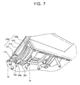
- a main body 100 (shown as a key phone terminal) is provided with a mounting recess 110 having a predetermined radius of curvature so that the LCD 200 is rotatably mounted in a vertical direction.
- the LCD 200 is provided with an upper case 210, a lower case 230, and an LCD plate 250 installed between the cases 210 and 230.
- a first rib 111 in line contact with a bottom surface of the curved portion 231 protrudes from the inner surface of the mounting recess 110
- a second rib 231a in line contact with the inner surface of the mounting recess 110 protrudes in an alternate position with the first rib 111 at a bottom surface of the curved portion 231.
- the height of the first rib 111 is made greater than that of the second rib 231a, and the bottom surface of the curved portion 231 initially contacts the upper surface of the first rib 111.
- the second rib 231a is additionally manufactured in consideration of the distribution of force or a difference between heights of each part, and the like.
- the LCD 200 is constructed so that the curved portion 231 can be smoothly and vertically rotated by line contact with the mounting recess 110, and thereby rotated by an angle regulator 270 ( see Fig. 6) at a predetermined angle, and then stopped.
- the angle regulator 270 includes: a plurality of bosses 271 protruding from the bottom surface of the LCD 200; a guide hole 272 formed along a curvature of the mounting recess 110 to form a passageway through which the boss 271 is rotated; a guide rail 273 protruding at both sides of the guide hole 272 toward the bottom surface of the mounting recess 110; and a slider 290 for sliding along the guide rail 273 and engaging with the boss 271.
- the slider 290 includes a pressing surface 291 contacting an upper surface of the guide rail 273, and side surfaces 293 and 295 bent at a right angle relative to both sides of the pressing surface 291 for insertion between both side surfaces of the guide rail 273.
- a gap d between both side surfaces 293 and 295 is, as shown in Fig. 6, smaller than a gap D between exterior surfaces of the guide rail 273 so as to achieve a tight fit therein. Therefore, when the LCD 200 is angularly adjusted, lateral movement (in a direction perpendicular to the side surface of the guide rail 273) is prevented.
- a first contact protrusion 297 in line contact with the upper surface of the guide rail 291 is formed at an inner portion of the pressing surface 291 of the slider 290, and a second contact protrusion 298 in surface contact with the exterior surface of the guide rail 273 is additionally formed at an inner portion of both side surfaces 293 and 295 of the slider 290.
- the first and second contact protrusions 297 and 298 serve to decrease contact area between the slider 290 and the guide rail 273.
- a boss groove 299 in which an upper end of the boss 271 is inserted, is additionally formed at the inner portion of the pressing surface 291 of the slider 290.
- a through-hole 299a is formed at a center portion of the boss groove 299 so as to connect the slider 290 and the boss 271 by passing through a fastening screw 301 ( see Fig. 6).
- the fastening screw 301 provides a force for supporting the LCD 200 rotated to a predetermined position by adjusting its tightening force.
- a rounded portion R (see Fig. 10) having a curvature corresponding to the curvature of the guide rail 273 is formed at lower ends of both side surfaces 293 and 295 of the slider 290.
- the slider 290 precisely engages the guide rail 273 so as to provide for smooth rotation of the LCD 200.
- the slider 290 uses POM (polyoxymethylene) as an abrasion resisting and self-lubricant material.
- the curved portion 231 protruding from the lower case 230 of the LCD 200 is slid along the mounting recess 110 of the main body 100.
- the curved portion 231 is rotated in line contact with the first rib 111 formed at the bottom surface of the mounting recess 110 and the second rib 231a (see Fig. 11) formed at the bottom surface of the curved portion 231 so as to be smoothly rotated.
- the slider 290 ( see Fig. 6) connected to the boss 271 is slid along the guide rail 273 during the rotation as described above, and the slider 290 is formed of a self-lubricant material to smoothly accomplish the sliding operation.
- both side surfaces 293 and 295 of the slider 290 are tightly fitted to the both side surfaces of the guide rail 273 so as to prevent the LCD 200 from moving laterally in a direction perpendicular to both surfaces of the guide rail 273 (see arrows A in Fig. 9) so as to provide for stable rotation of the LCD 200.
- the LCD 200 When the user releases the force from the LCD 200, the LCD 200 maintains the rotated angle. At this point, since the tightening force of the fastening screw 301 is greater than the rotational force by weight of the LCD 200, the LCD 200 can be maintained in position.
- the present invention has the advantage of smoother rotation of the LCD 200 due to formation of the curved portion 231 at the bottom surface of the LCD 200, provision of the mounting recess 110 corresponding to the curved portion 231 at the main body, and formation of the first rib 111 and second rib 231a at the mounting recess 110 and the curved portion 231, respectively, so that the LCD 200 is rotated by line contact.
- the present invention has another advantage of decreased noise when adjusting the angle due to use of the guide rail 273 and the slider 290 during rotation of the LCD 200.
- the present invention has a further advantage in that shaking of the LCD 200 is reduced by decreasing tolerance of parts through simplification of the composition of the angle adjusting device resulting, in part, from use of guide rail 273 and the slider 290 during rotation of the LCD 200.
Applications Claiming Priority (2)
| Application Number | Priority Date | Filing Date | Title |
|---|---|---|---|
| KR2004005519 | 2004-01-28 | ||
| KR1020040005519A KR100602639B1 (ko) | 2004-01-28 | 2004-01-28 | 액정표시기의 회전장치 |
Publications (2)
| Publication Number | Publication Date |
|---|---|
| EP1559948A2 true EP1559948A2 (fr) | 2005-08-03 |
| EP1559948A3 EP1559948A3 (fr) | 2005-09-21 |
Family
ID=34651528
Family Applications (1)
| Application Number | Title | Priority Date | Filing Date |
|---|---|---|---|
| EP05001598A Withdrawn EP1559948A3 (fr) | 2004-01-28 | 2005-01-26 | Dispositif de pivotement pour dispositif d'affichage à cristaux liquides |
Country Status (5)
| Country | Link |
|---|---|
| US (1) | US7466820B2 (fr) |
| EP (1) | EP1559948A3 (fr) |
| KR (1) | KR100602639B1 (fr) |
| CN (1) | CN100587849C (fr) |
| AU (1) | AU2004240140B2 (fr) |
Families Citing this family (23)
| Publication number | Priority date | Publication date | Assignee | Title |
|---|---|---|---|---|
| EP1696303B1 (fr) * | 2005-02-28 | 2007-09-26 | Seiko Epson Corporation | Dispositif de traitement de données |
| US7878666B2 (en) * | 2005-06-30 | 2011-02-01 | Brother Kogyo Kabushiki Kaisha | Multi-function device with pivoting display |
| CN101123124B (zh) * | 2006-08-08 | 2010-07-14 | 明基电通股份有限公司 | 可调整倾斜角度的支撑装置及具有该支撑装置的显示器 |
| US20090045305A1 (en) * | 2007-07-20 | 2009-02-19 | Seiko Epson Corporation | Tilt device and electronic equipment |
| TW200908729A (en) * | 2007-08-15 | 2009-02-16 | Hi Touch Imaging Tech Co Ltd | Mechanism utilized to adjust inclination angle and horizontal rotation angle |
| CN101561073B (zh) * | 2008-04-14 | 2010-09-22 | 星乔科技股份有限公司 | 显示器底座 |
| KR100974138B1 (ko) * | 2008-12-11 | 2010-08-04 | 엘지에릭슨 주식회사 | 엘시디모듈을 회전가능하게 지지하는 지지장치 |
| GB2468322B (en) * | 2009-03-04 | 2011-03-16 | Dyson Technology Ltd | Tilting fan stand |
| GB2468312A (en) | 2009-03-04 | 2010-09-08 | Dyson Technology Ltd | Fan assembly |
| TWI377898B (en) * | 2009-06-17 | 2012-11-21 | Wistron Corp | Electronic device having a display screen |
| CN101931664B (zh) * | 2009-06-25 | 2013-11-06 | 纬创资通股份有限公司 | 具有显示屏幕的电子装置 |
| JP4996753B1 (ja) * | 2011-02-14 | 2012-08-08 | 株式会社東芝 | テレビジョン受像機、及び電子機器 |
| TWI470404B (zh) * | 2011-04-07 | 2015-01-21 | Wistron Corp | 用來調整螢幕模組之觀賞角度的調整裝置及其電腦系統 |
| US9239128B2 (en) * | 2011-05-31 | 2016-01-19 | Canon Kabushiki Kaisha | Image forming apapratus |
| CN102927423B (zh) * | 2012-10-25 | 2015-02-18 | 歌尔声学股份有限公司 | 功能器件的伸缩装置及控制方法 |
| CN102927238B (zh) * | 2012-10-25 | 2016-06-01 | 歌尔声学股份有限公司 | 运动线路转换装置 |
| US9944235B2 (en) * | 2013-11-16 | 2018-04-17 | The Boeing Company | Stowable computer workstation |
| CN105487598B (zh) * | 2014-09-16 | 2020-03-24 | 联想(北京)有限公司 | 一种电子设备和信息处理方法 |
| TWM533841U (en) * | 2016-08-09 | 2016-12-11 | Leohab Entpr Co Ltd | Hinge of electronic device support |
| US9784406B1 (en) * | 2016-11-25 | 2017-10-10 | Leohab Enterprise Co., Ltd. | Pivotal device for a support of an electric device |
| KR102400745B1 (ko) * | 2017-03-28 | 2022-05-23 | 삼성전자주식회사 | 전자 장치용 도킹 스테이션 |
| US11181738B2 (en) * | 2018-11-14 | 2021-11-23 | Panasonic Automotive Systems Company Of America, Division Of Panasonic Corporation Of North America | Rotationally adjustable head up display |
| CN111520590B (zh) * | 2020-05-07 | 2021-06-08 | 刘佳越 | 一种新媒体推广室外展示装置 |
Citations (7)
| Publication number | Priority date | Publication date | Assignee | Title |
|---|---|---|---|---|
| US4571456A (en) | 1982-10-18 | 1986-02-18 | Grid Systems Corporation | Portable computer |
| US5497296A (en) | 1991-07-30 | 1996-03-05 | Kabushiki Kaisha Toshiba | Electronic apparatus with hinged display and latch mechanism for releasably latching display in closed position |
| KR970031647A (ko) | 1995-11-22 | 1997-06-26 | 김광호 | 전화기의 액정표시기(lcd) 각도 조절장치 |
| US5689400A (en) | 1994-05-31 | 1997-11-18 | Kabushiki Kaisha Toshiba | Portable electronic apparatus including space-saving component mounting features |
| US5691880A (en) | 1993-04-30 | 1997-11-25 | Kabushiki Kaisha Toshiba | Portable electronic apparatus having a hinge mechanism which rotatably connects a flat display unit to a housing incorporating a frame for supporting a circuit board |
| US5796579A (en) | 1994-05-31 | 1998-08-18 | Kabushiki Kaisha Toshiba | Portable electronic apparatus having expansion connector covered by pivotally mounted upper and lower covers having laterally extending guide portions |
| KR100299130B1 (ko) | 1998-08-20 | 2001-09-06 | 윤종용 | 액정표시장치의각도조절구조 |
Family Cites Families (7)
| Publication number | Priority date | Publication date | Assignee | Title |
|---|---|---|---|---|
| JPS59140727A (ja) * | 1983-01-31 | 1984-08-13 | Fujitsu Ltd | 周波数変換方式 |
| US4533105A (en) | 1984-04-27 | 1985-08-06 | Zenith Electronics Corporation | Tiltable display monitor assembly |
| US4989167A (en) | 1989-09-11 | 1991-01-29 | Jeffrey Kapec | Desktop computer terminal having an angularly adjustable electronic display module |
| US5257164A (en) | 1992-10-13 | 1993-10-26 | Compuadd Corporation | Counter-top touch-screen interface terminal chassis having a plurality of positions |
| JP3588702B2 (ja) | 1995-04-03 | 2004-11-17 | Necインフロンティア株式会社 | 情報処理用端末機における仰角可変部材の取付装置 |
| US5881985A (en) | 1997-02-04 | 1999-03-16 | Apple Computer, Inc. | Tilting, swiveling, locking base for monitors |
| TW540970U (en) | 2002-10-22 | 2003-07-01 | Hon Hai Prec Ind Co Ltd | A device for rotating and locating a storage bracket |
-
2004
- 2004-01-28 KR KR1020040005519A patent/KR100602639B1/ko not_active IP Right Cessation
- 2004-12-07 US US11/004,825 patent/US7466820B2/en not_active Expired - Fee Related
- 2004-12-14 AU AU2004240140A patent/AU2004240140B2/en not_active Ceased
- 2004-12-24 CN CN200410103660A patent/CN100587849C/zh not_active Expired - Fee Related
-
2005
- 2005-01-26 EP EP05001598A patent/EP1559948A3/fr not_active Withdrawn
Patent Citations (10)
| Publication number | Priority date | Publication date | Assignee | Title |
|---|---|---|---|---|
| US4571456A (en) | 1982-10-18 | 1986-02-18 | Grid Systems Corporation | Portable computer |
| US4571456B1 (en) | 1982-10-18 | 1995-08-15 | Grid Systems Corp | Portable computer |
| US5497296A (en) | 1991-07-30 | 1996-03-05 | Kabushiki Kaisha Toshiba | Electronic apparatus with hinged display and latch mechanism for releasably latching display in closed position |
| US5691880A (en) | 1993-04-30 | 1997-11-25 | Kabushiki Kaisha Toshiba | Portable electronic apparatus having a hinge mechanism which rotatably connects a flat display unit to a housing incorporating a frame for supporting a circuit board |
| US5689400A (en) | 1994-05-31 | 1997-11-18 | Kabushiki Kaisha Toshiba | Portable electronic apparatus including space-saving component mounting features |
| US5764476A (en) | 1994-05-31 | 1998-06-09 | Kabushiki Kaisha Toshiba | Portable electronic apparatus having a base a display and a microphone |
| US5796579A (en) | 1994-05-31 | 1998-08-18 | Kabushiki Kaisha Toshiba | Portable electronic apparatus having expansion connector covered by pivotally mounted upper and lower covers having laterally extending guide portions |
| US5808860A (en) | 1994-05-31 | 1998-09-15 | Kabushiki Kaisha Toshiba | Portable electronic apparatus with detachably mounted keyboard |
| KR970031647A (ko) | 1995-11-22 | 1997-06-26 | 김광호 | 전화기의 액정표시기(lcd) 각도 조절장치 |
| KR100299130B1 (ko) | 1998-08-20 | 2001-09-06 | 윤종용 | 액정표시장치의각도조절구조 |
Also Published As
| Publication number | Publication date |
|---|---|
| AU2004240140A1 (en) | 2005-08-11 |
| KR100602639B1 (ko) | 2006-07-19 |
| EP1559948A3 (fr) | 2005-09-21 |
| CN1649035A (zh) | 2005-08-03 |
| US20050163558A1 (en) | 2005-07-28 |
| AU2004240140B2 (en) | 2007-04-26 |
| CN100587849C (zh) | 2010-02-03 |
| KR20050077610A (ko) | 2005-08-03 |
| US7466820B2 (en) | 2008-12-16 |
| AU2004240140B8 (en) | 2005-08-11 |
Similar Documents
| Publication | Publication Date | Title |
|---|---|---|
| EP1559948A2 (fr) | Dispositif de pivotement pour dispositif d'affichage à cristaux liquides | |
| EP1524394B1 (fr) | Ensemble charnière et boîtier | |
| RU2389149C2 (ru) | Комбинированный механизм для скользящих и вращательных движений и переносное электронное устройство, содержащее такой механизм | |
| JP4192024B2 (ja) | 携帯端末用取付装置 | |
| US8243432B2 (en) | Support mechanism for portable electronic device | |
| JP5473664B2 (ja) | スタンド装置及び該スタンド装置を用いる携帯式電子装置 | |
| EP1742449B1 (fr) | Module de coulissement et terminal portable comprenant un tel module | |
| JP2637387B2 (ja) | 携帯用電話機のヒンジ機構 | |
| WO2002089343A1 (fr) | Charniere | |
| JP4783847B2 (ja) | 携帯端末 | |
| US20110032668A1 (en) | Slide-type opening/closing device and portable electronic apparatus | |
| US20100137041A1 (en) | Sliding rotating apparatus | |
| US20120275099A1 (en) | Portable electronic device | |
| US8164890B2 (en) | Sliding and tilting mechanism and portable electronic device using the same | |
| KR19980065142A (ko) | 힌지 장치 | |
| US8332001B2 (en) | Sliding mechanism and portable electronic device using the same | |
| US8276856B2 (en) | Support mechanism having two detachable covers and hinge | |
| KR100856221B1 (ko) | 힌지 장치를 구비하는 휴대용 단말기 | |
| KR100299130B1 (ko) | 액정표시장치의각도조절구조 | |
| KR20040006978A (ko) | 슬라이딩 타입 휴대용 무선 단말기 | |
| KR101006046B1 (ko) | 휴대용 통신단말기를 개폐하기 위한 슬라이드 조립체 | |
| KR100714512B1 (ko) | 가로 방향 또는 세로 방향으로 열릴 수 있는 폴더형이동통신 단말기 | |
| KR19980014749U (ko) | 휴대용 무선전화기의 플립커버 개폐장치 | |
| KR20100080501A (ko) | 휴대용 통신단말기를 개폐하기 위한 슬라이드 조립체 | |
| KR200439581Y1 (ko) | 슬라이드 힌지 모듈 |
Legal Events
| Date | Code | Title | Description |
|---|---|---|---|
| PUAI | Public reference made under article 153(3) epc to a published international application that has entered the european phase |
Free format text: ORIGINAL CODE: 0009012 |
|
| 17P | Request for examination filed |
Effective date: 20050126 |
|
| AK | Designated contracting states |
Kind code of ref document: A2 Designated state(s): AT BE BG CH CY CZ DE DK EE ES FI FR GB GR HU IE IS IT LI LT LU MC NL PL PT RO SE SI SK TR |
|
| AX | Request for extension of the european patent |
Extension state: AL BA HR LV MK YU |
|
| PUAL | Search report despatched |
Free format text: ORIGINAL CODE: 0009013 |
|
| AK | Designated contracting states |
Kind code of ref document: A3 Designated state(s): AT BE BG CH CY CZ DE DK EE ES FI FR GB GR HU IE IS IT LI LT LU MC NL PL PT RO SE SI SK TR |
|
| AX | Request for extension of the european patent |
Extension state: AL BA HR LV MK YU |
|
| AKX | Designation fees paid |
Designated state(s): DE FR GB |
|
| 17Q | First examination report despatched |
Effective date: 20061106 |
|
| GRAP | Despatch of communication of intention to grant a patent |
Free format text: ORIGINAL CODE: EPIDOSNIGR1 |
|
| STAA | Information on the status of an ep patent application or granted ep patent |
Free format text: STATUS: THE APPLICATION IS DEEMED TO BE WITHDRAWN |
|
| 18D | Application deemed to be withdrawn |
Effective date: 20120307 |