EP1559842A1 - Deck, in particular for recreation purpose - Google Patents
Deck, in particular for recreation purpose Download PDFInfo
- Publication number
- EP1559842A1 EP1559842A1 EP05360002A EP05360002A EP1559842A1 EP 1559842 A1 EP1559842 A1 EP 1559842A1 EP 05360002 A EP05360002 A EP 05360002A EP 05360002 A EP05360002 A EP 05360002A EP 1559842 A1 EP1559842 A1 EP 1559842A1
- Authority
- EP
- European Patent Office
- Prior art keywords
- floor
- post
- sleeve
- central
- floor according
- Prior art date
- Legal status (The legal status is an assumption and is not a legal conclusion. Google has not performed a legal analysis and makes no representation as to the accuracy of the status listed.)
- Granted
Links
Images


Classifications
-
- E—FIXED CONSTRUCTIONS
- E04—BUILDING
- E04H—BUILDINGS OR LIKE STRUCTURES FOR PARTICULAR PURPOSES; SWIMMING OR SPLASH BATHS OR POOLS; MASTS; FENCING; TENTS OR CANOPIES, IN GENERAL
- E04H1/00—Buildings or groups of buildings for dwelling or office purposes; General layout, e.g. modular co-ordination or staggered storeys
- E04H1/12—Small buildings or other erections for limited occupation, erected in the open air or arranged in buildings, e.g. kiosks, waiting shelters for bus stops or for filling stations, roofs for railway platforms, watchmen's huts or dressing cubicles
- E04H1/1205—Small buildings erected in the open air
-
- E—FIXED CONSTRUCTIONS
- E04—BUILDING
- E04B—GENERAL BUILDING CONSTRUCTIONS; WALLS, e.g. PARTITIONS; ROOFS; FLOORS; CEILINGS; INSULATION OR OTHER PROTECTION OF BUILDINGS
- E04B1/00—Constructions in general; Structures which are not restricted either to walls, e.g. partitions, or floors or ceilings or roofs
- E04B1/34—Extraordinary structures, e.g. with suspended or cantilever parts supported by masts or tower-like structures enclosing elevators or stairs; Features relating to the elastic stability
- E04B1/3408—Extraordinarily-supported small buildings
- E04B1/3412—Extraordinarily-supported small buildings mainly supported by a central column or footing
-
- A—HUMAN NECESSITIES
- A63—SPORTS; GAMES; AMUSEMENTS
- A63B—APPARATUS FOR PHYSICAL TRAINING, GYMNASTICS, SWIMMING, CLIMBING, OR FENCING; BALL GAMES; TRAINING EQUIPMENT
- A63B9/00—Climbing poles, frames, or stages
- A63B2009/006—Playground structures
-
- A—HUMAN NECESSITIES
- A63—SPORTS; GAMES; AMUSEMENTS
- A63B—APPARATUS FOR PHYSICAL TRAINING, GYMNASTICS, SWIMMING, CLIMBING, OR FENCING; BALL GAMES; TRAINING EQUIPMENT
- A63B2208/00—Characteristics or parameters related to the user or player
- A63B2208/12—Characteristics or parameters related to the user or player specially adapted for children
Definitions
- the present invention relates to the field of furniture including devices that can be used as play equipment or sports, and in particular game elements having floors mounted on a central post and provided with support posts for elements guardrail, and has for object such a floor.
- support posts of railing elements equipping these floors are also mounted most often projecting on the edges of said floors via devices protruding partially under the floor and possibly on the periphery of this latest.
- the present invention aims to overcome these disadvantages, by proposing a floor, especially a play piece, mounted on a central pole allowing the realization of aesthetic structures, simple and fast assembly and presenting no roughness likely to be dangerous for users.
- the floor, in particular game element, mounted on a central post is characterized in that it is in the form of a polygonal platform, round or oval, provided with a central sleeve fitting on a support pole and fixed on an abutment corresponding pole of said post by means of assembly means, whose ends are protected against direct accidental access.
- FIG. 1 of the attached drawings shows a game element essentially constituted by a floor 1 mounted on a central pole 2 and provided with posts 3 for fastening guardrail elements (not shown).
- the central post 2 can be anchored to the ground by via a lower mounting plate 2 'intended to cooperate with an anchor usually consisting of a mass of concrete in which are drilled threaded rods cooperating with their end with corresponding holes in the plate 2 'and with nuts (no shown).
- this game element may be supplemented by a 4 forming a roof, as well as elements 5 and 6 for access to the floor 1, which can be in the form of apparatus or other.
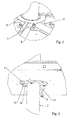
- the floor 1 is under form of a polygonal platform, round or oval, provided with a sleeve central 7 fitting on the support post 2 and fixed on a stop 2 "corresponding ( Figure 2) of said pole 2 through means 8, the ends of which are protected against access accidental direct.
- the polygonal platform, round or oval forming the floor 1 is formed as a hollow body having a flat surface and one or more peripheral edges, this or these edges peripherals being connected to the central sleeve via radii sections 9 connecting said central sleeve 7 to the corners of the polygon between the peripheral rims or connecting said peripheral rim at intervals regular in the case of a round or oval shape.
- the edge (s) floor 1 peripherals, as well as the profiled spokes 9 to stiffen the floor 1.
- the profiled rays 9 are advantageously under form of angle elements delimiting with the corresponding face of the floor a zone at least partially closed and the edge or edges peripherals also have an angle section also delimiting an area at least partially closed.
- the central sleeve 7 is advantageously provided with a circular ring 7 'extending from level with the profiled rays 9 and covering the ends of the means assembly 8 of the floor 1 on the corresponding stop 2 "of the post central 2.
- the floor 1 is provided at the intersection between the profiled rays 9 and the Peripheral edges of sleeves 10 receiving posts 3 fixing of guardrail elements, each post 3 being fixed in position by through an assembly means 13 through holes of the corresponding sleeve 10 and the post 3 in position assembly of the post 3 in the sleeve 10, one end of the means 13 being, in the service position, covered by the radius profile 9.
- the assembly means 8 and 13 have, at their end extending outside the hollow body forming the floor 1, devices 14 for guiding and dressing. These devices 14, which can be in the form of washers or other items extending around end corresponding to the assembly means 8 and 13, provide a lateral wrap of said ends and thus make them less dangerous in case of shock.
- the assembly elements 8 and 13 being generally consist of bolts, the corresponding screw head, located outside the hollow body forming the floor 1, can thus be completely surrounded by a device 14 forming a boss and realizing thus a gently sloping connection between the top of the screw head and the face bearing on the outside of the hollow body forming the floor 1.
- the floor 1 is advantageously provided with a covering element 15 at least two parts that can be mounted on the hollow body forming the floor 1 and being fastened to the latter by bolting, screwing or snap.
- Bolting or screwing the parts forming the element of recovery 15 can be performed by means of screws passing through said parts and cooperating with threads provided for in, or with nuts inserted in the profiled rays 9, in the circular ring 7 'of the sleeve 7 and in the peripheral edge or rims of the floor 1.
- these said parts can advantageously be provided a rim extending perpendicular to their plane and provided with a rib or engagement groove with the edges of the edge or flanges peripherals of the floor 1, the circular ring 7 'of the sleeve 7 and profiled rays.9.
- the floor 1 is preferably mounted on the pole central support 2 with its hollow part facing up, the element covering 15 being fixed from above on said floor 1.
- This last embodiment makes it possible to obtain a floor simpler and therefore a lower cost while ensuring the same safety of users against risk of injury by snagging accidental to any means of assembly.
- the structures having a floor conforming to the invention are particularly fast and simple mounting.
Abstract
Description
La présente invention concerne le domaine des mobiliers urbains, notamment des dispositifs utilisables comme équipements de jeu ou de sport, et en particulier des éléments de jeu comportant des planchers montés sur poteau central et pourvus de potelets de support d'éléments garde-corps, et a pour objet un tel plancher.The present invention relates to the field of furniture including devices that can be used as play equipment or sports, and in particular game elements having floors mounted on a central post and provided with support posts for elements guardrail, and has for object such a floor.
Actuellement, les planchers montés sur poteau central d'éléments de jeu sont généralement montés sur le poteau de support au moyen de pièces de fixation, dont une partie est en saillie sous la face inférieure de ces planchers et risque ainsi de former un danger de blessure pour des enfants utilisant le jeu.Currently, floors mounted on central pole game elements are usually mounted on the support pole at means of fasteners, part of which is projecting under the face lower of these floors and thus may constitute a danger of injury for children using the game
En outre, les potelets de support d'éléments garde-corps équipant ces planchers sont également montés le plus souvent en saillie sur les bords desdits planchers par l'intermédiaire de dispositifs dépassant partiellement sous le plancher et éventuellement sur la périphérie de ce dernier.In addition, the support posts of railing elements equipping these floors are also mounted most often projecting on the edges of said floors via devices protruding partially under the floor and possibly on the periphery of this latest.
La présente invention a pour but de pallier ces inconvénients, en proposant un plancher, en particulier d'élément de jeu, monté sur un poteau central permettant la réalisation de structures esthétiques, de montage simple et rapide et ne présentant aucune aspérité susceptible d'être dangereuse pour les utilisateurs.The present invention aims to overcome these disadvantages, by proposing a floor, especially a play piece, mounted on a central pole allowing the realization of aesthetic structures, simple and fast assembly and presenting no roughness likely to be dangerous for users.
A cet effet, le plancher, en particulier d'élément de jeu, monté sur un poteau central est caractérisé en ce qu'il se présente sous forme d'une plate-forme polygonale, ronde ou ovale, munie d'un manchon central d'emmanchement sur un poteau de support et fixée sur une butée correspondante dudit poteau par l'intermédiaire de moyens d'assemblage, dont les extrémités sont protégées contre un accès accidentel direct.For this purpose, the floor, in particular game element, mounted on a central post is characterized in that it is in the form of a polygonal platform, round or oval, provided with a central sleeve fitting on a support pole and fixed on an abutment corresponding pole of said post by means of assembly means, whose ends are protected against direct accidental access.
L'invention sera mieux comprise, grâce à la description ci-après,
qui se rapporte à un mode de réalisation préféré, donné à titre
d'exemple non limitatif, et expliqué avec référence aux dessins
schématiques annexés, dans lesquels :
La figure 1 des dessins annexés représente un élément de jeu
essentiellement constitué par un plancher 1 monté sur un poteau central 2 et
pourvu de potelets 3 de fixation d'éléments garde-corps (non représentés).
De manière connue, le poteau central 2 peut être ancré au sol par
l'intermédiaire d'une platine de fixation inférieure 2' destinée à coopérer
avec un plot d'ancrage généralement constitué par une masse de béton dans
laquelle sont noyées des tiges filetées coopérant par leur extrémité avec
perçages correspondants de la platine 2' et avec des écrous (non
représentés). En outre, cet élément de jeu peut être complété par une partie
supérieure 4 formant un toit, ainsi que par des éléments 5 et 6 d'accès au
plancher 1, qui peuvent être sous forme d'agrès ou autre.Figure 1 of the attached drawings shows a game element
essentially constituted by a floor 1 mounted on a
Conformément à l'invention, le plancher 1 se présente sous
forme d'une plate-forme polygonale, ronde ou ovale, munie d'un manchon
central 7 d'emmanchement sur le poteau de support 2 et fixée sur une butée
2" correspondante (figure 2) dudit poteau 2 par l'intermédiaire de moyens
d'assemblage 8, dont les extrémités sont protégées contre un accès
accidentel direct. De préférence, la plate-forme polygonale, ronde ou ovale
formant le plancher 1 est constituée sous forme d'un corps creux présentant
une surface plane et un ou des rebords périphériques, ce ou ces rebords
périphériques étant reliés au manchon central par l'intermédiaire de rayons
profilés 9 reliant ledit manchon central 7 aux angles du polygone entre les
rebords périphériques ou reliant ledit rebord périphérique à intervalles
réguliers dans le cas d'une forme ronde ou ovale. Le ou les rebords
périphériques du plancher 1, ainsi que les rayons profilés 9 permettent
d'assurer une rigidification du plancher 1.According to the invention, the floor 1 is under
form of a polygonal platform, round or oval, provided with a sleeve
central 7 fitting on the
Les rayons profilés 9 se présentent avantageusement sous
forme d'éléments en cornière délimitant avec la face correspondante du
plancher une zone au moins partiellement fermée et le ou les rebords
périphériques présentent également une section en cornière délimitant aussi
une zone au moins partiellement fermée. Par ailleurs, le manchon central 7
est avantageusement pourvu d'un anneau circulaire 7' s'étendant de niveau
avec les rayons profilés 9 et recouvrant les extrémités des moyens
d'assemblage 8 du plancher 1 sur la butée 2" correspondante du poteau
central 2. Ainsi, il est possible de loger une extrémité des moyens
d'assemblage du plancher 1 sur le poteau central 2, ainsi que d'assemblage
des éléments 5 et 6 d'accès au plancher 1 sur ce dernier, dans les zones
partiellement recouvertes par l'anneau circulaire 7' et par le ou les rebords
périphériques du plancher 1.The profiled
En outre, selon une autre caractéristique de l'invention, le
plancher 1 est pourvu à l'intersection entre les rayons profilés 9 et le ou les
rebords périphériques de manchons 10 de réception de potelets 3 de fixation
d'éléments garde-corps, chaque potelet 3 étant fixé en position par
l'intermédiaire d'un moyen d'assemblage 13 traversant des perçages
correspondants du manchon correspondant 10 et du potelet 3 en position
d'assemblage du potelet 3 dans le manchon 10, une extrémité du moyen
d'assemblage 13 étant, en position de service, recouverte par le rayon
profilé 9.In addition, according to another characteristic of the invention, the
floor 1 is provided at the intersection between the profiled
De préférence, les moyens d'assemblage 8 et 13 présentent, à
leur extrémité s'étendant à l'extérieur du corps creux formant le plancher 1,
des dispositifs 14 de guidage et d'habillage. Ces dispositifs 14, qui peuvent
être sous forme de rondelles ou autres éléments s'étendant autour de
l'extrémité correspondant aux moyens d'assemblage 8 et 13, assurent un
enveloppement latéral desdites extrémités et rendent ainsi celles-ci moins
dangereuses en cas de choc. Les éléments d'assemblage 8 et 13 étant
généralement constitués par des boulons, la tête de vis correspondante,
située à l'extérieur du corps creux formant le plancher 1, peut ainsi être
complètement entourée par un dispositif 14 formant un bossage et réalisant
ainsi une liaison en pente douce entre le sommet de la tête de vis et la face
d'appui sur l'extérieur du corps creux formant le plancher 1.Preferably, the assembly means 8 and 13 have, at
their end extending outside the hollow body forming the floor 1,
Conformément à une autre caractéristique de l'invention, le
plancher 1 est avantageusement pourvu d'un élément de recouvrement 15 en
au moins deux parties pouvant être montées sur le corps creux formant le
plancher 1 et étant fixées à ce dernier par boulonnage, par vissage ou par
encliquetage. Le boulonnage ou le vissage des parties formant l'élément de
recouvrement 15 peut être effectué au moyen de vis traversant lesdites
parties et coopérant avec des taraudages prévus dans, ou encore avec des
écrous insérés dans les rayons profilés 9, dans l'anneau circulaire 7' du
manchon 7 et dans le ou les rebords périphériques du plancher 1. Dans le
cas d'un montage par encliquetage des parties formant l'élément de
recouvrement 15, cesdites parties peuvent avantageusement être pourvues
d'un rebord s'étendant perpendiculairement à leur plan et muni d'une
nervure ou d'une rainure d'engagement avec les arêtes du ou des rebords
périphériques du plancher 1, de l'anneau circulaire 7' du manchon 7 et des
rayons profilés.9.According to another characteristic of the invention, the
floor 1 is advantageously provided with a covering
Dans le mode de réalisation représenté à titre d'exemple aux
dessins annexés, le plancher 1 est préférentiellement monté sur le poteau
central de support 2 avec sa partie en creux tournée vers le haut, l'élément
de recouvrement 15 étant fixé par le dessus sur ledit plancher 1.In the embodiment shown by way of example to
drawings attached, the floor 1 is preferably mounted on the pole
Cependant, selon une variante de réalisation de l'invention, non
représentée aux dessins annexés, il est également possible de monter le
plancher 1 seul sur le poteau central de support 2 avec sa partie en creux
tournée vers le bas, sa fixation sur le poteau 2 étant alors réalisée par
l'intermédiaire de l'anneau circulaire 7' du manchon 7 s'appuyant sur la
butée 2" dudit poteau 2 et étant solidarisée avec cette dernière par
l'intermédiaire des moyens d'assemblage 8. Dans un tel cas, les extrémités
des moyens d'assemblage 8 restent parfaitement dissimulés dans une zone
ne pouvant être atteintes directement et les moyens d'assemblage 13 des
potelets 3 restent également dissimulés à un contact accidentel direct par les
rayons profilés 9, les potelets 3 étant simplement montés dans les manchons
10 correspondants par le côté opposé de ce manchon 10. Il en est de même
en ce qui concerne les moyens d'assemblage des éléments 5 et 6 d'accès au
plancher 1.However, according to an alternative embodiment of the invention, no
shown in the accompanying drawings, it is also possible to mount the
floor 1 only on the
Ce dernier mode de réalisation permet l'obtention d'un plancher plus simple et donc d'un moindre coût de revient tout en assurant la même sécurité des utilisateurs contre un risque de blessures par accrochage accidentel à un quelconque moyen d'assemblage.This last embodiment makes it possible to obtain a floor simpler and therefore a lower cost while ensuring the same safety of users against risk of injury by snagging accidental to any means of assembly.
Grâce à l'invention, il est possible de réaliser des structures, en particulier de jeu, munies d'un plancher monté sur poteau central unique, présentant une esthétique améliorée par rapport aux structures de ce type existant à ce jour et ne présentant aucune aspérité sur leur surface extérieure susceptible de présenter un risque de blessure par heurt accidentel, tous les éléments d'assemblage étant montés de manière protégée.Thanks to the invention, it is possible to produce structures, play area, equipped with a floor mounted on a single central post, having improved aesthetics compared to structures of this type existing to date and showing no roughness on their outer surface likely to present a risk of injury by accidental collision, all assembly elements being mounted in a protected manner.
Par ailleurs, les structures présentant un plancher conforme à l'invention sont de montage particulièrement rapide et simple. Furthermore, the structures having a floor conforming to the invention are particularly fast and simple mounting.
Bien entendu, l'invention n'est pas limitée au mode de réalisation décrit et représenté aux dessins annexés. Des modifications restent possibles, notamment du point de vue de la constitution des divers éléments ou par substitution d'équivalents techniques, sans sortir pour autant du domaine de protection de l'invention.Of course, the invention is not limited to the mode of embodiment described and shown in the accompanying drawings. Modifications remain possible, particularly from the point of view of the constitution of the various elements or by substituting technical equivalents, without going out for as much of the field of protection of the invention.
Claims (11)
Applications Claiming Priority (2)
| Application Number | Priority Date | Filing Date | Title |
|---|---|---|---|
| FR0400734A FR2865488B1 (en) | 2004-01-27 | 2004-01-27 | FLOOR, ESPECIALLY GAME ELEMENT |
| FR0400734 | 2004-01-27 |
Publications (2)
| Publication Number | Publication Date |
|---|---|
| EP1559842A1 true EP1559842A1 (en) | 2005-08-03 |
| EP1559842B1 EP1559842B1 (en) | 2007-06-06 |
Family
ID=34639785
Family Applications (1)
| Application Number | Title | Priority Date | Filing Date |
|---|---|---|---|
| EP05360002A Not-in-force EP1559842B1 (en) | 2004-01-27 | 2005-01-18 | Deck, in particular for recreation purpose |
Country Status (4)
| Country | Link |
|---|---|
| EP (1) | EP1559842B1 (en) |
| AT (1) | ATE364112T1 (en) |
| DE (1) | DE602005001273D1 (en) |
| FR (1) | FR2865488B1 (en) |
Families Citing this family (1)
| Publication number | Priority date | Publication date | Assignee | Title |
|---|---|---|---|---|
| USD807978S1 (en) * | 2015-12-22 | 2018-01-16 | Landscape Structures Inc. | Multi-activity play structure |
Citations (2)
| Publication number | Priority date | Publication date | Assignee | Title |
|---|---|---|---|---|
| DE4232410C1 (en) * | 1992-09-28 | 1994-01-27 | Erhard Baier | Mobile children's playground - has all equipment fixed to platform transportable as complete unit |
| EP1022036A2 (en) * | 1999-01-20 | 2000-07-26 | Playcore, Inc. | Recreation deck with central load bearing member |
-
2004
- 2004-01-27 FR FR0400734A patent/FR2865488B1/en not_active Expired - Fee Related
-
2005
- 2005-01-18 EP EP05360002A patent/EP1559842B1/en not_active Not-in-force
- 2005-01-18 AT AT05360002T patent/ATE364112T1/en not_active IP Right Cessation
- 2005-01-18 DE DE602005001273T patent/DE602005001273D1/en active Active
Patent Citations (2)
| Publication number | Priority date | Publication date | Assignee | Title |
|---|---|---|---|---|
| DE4232410C1 (en) * | 1992-09-28 | 1994-01-27 | Erhard Baier | Mobile children's playground - has all equipment fixed to platform transportable as complete unit |
| EP1022036A2 (en) * | 1999-01-20 | 2000-07-26 | Playcore, Inc. | Recreation deck with central load bearing member |
Also Published As
| Publication number | Publication date |
|---|---|
| FR2865488A1 (en) | 2005-07-29 |
| EP1559842B1 (en) | 2007-06-06 |
| DE602005001273D1 (en) | 2007-07-19 |
| FR2865488B1 (en) | 2006-04-21 |
| ATE364112T1 (en) | 2007-06-15 |
Similar Documents
| Publication | Publication Date | Title |
|---|---|---|
| CA1158953A (en) | Clamping ring for umbrella | |
| FR2654058A1 (en) | DEVICE FOR HOLDING A TUBULAR MEMBER IN PARTICULAR A STEERING COLUMN OF A MOTOR VEHICLE. | |
| CA2239933C (en) | Connecting device for a handrail | |
| FR3047260B1 (en) | BODY WELDER | |
| EP1801323B1 (en) | Device for fixing a rail on a post | |
| EP1559842B1 (en) | Deck, in particular for recreation purpose | |
| FR2811583A1 (en) | Snowboard binding comprises a base plate, a curved part, a curved supporting plate, and fixing screws fixing the supporting plate to the curved part and the curved part to the base plate which are arranged coaxially and have a common nut | |
| EP0651110B1 (en) | Immobilization device of a vertical stiffener of railings opposing a floor support | |
| EP0462039B1 (en) | Modular toy device | |
| FR2764925A1 (en) | FOOT-FORMING DEVICE FOR STAKE OR MAT | |
| FR2947851A1 (en) | Safety balustrade forming device for terraced roof of building, has rail fixed at upper ends of bent parts of posts, and studs for allowing fixation of panels, where panels are inclined with respect to horizontal in fixation position | |
| EP0936360B1 (en) | Assembling device, in particular for tubular elements | |
| WO2008122291A1 (en) | Device for attaching a rail to a post | |
| FR2978780A1 (en) | Device for articulately connecting tube profiles as abutting portions of e.g. guard rails, has structural components including parts, where parts not connected by connections are fitted on or in tubular elements ends to be joined | |
| EP2045513B1 (en) | Lighting device such as a candelabra on a column | |
| EP1988236B1 (en) | Device for fixing a runner on a post | |
| EP1813740A1 (en) | Shelter | |
| FR2883583A1 (en) | TELESCOPIC SHELTER | |
| EP2873785B1 (en) | Self-supporting guardrail shoe | |
| EP0158755B1 (en) | Modular safety walk, especially for servicing cable bearing rocker bogies of rope railway systems | |
| FR2625775A1 (en) | Assembly system for the elements of a tubular structure | |
| EP0199657B1 (en) | Volleyball net support | |
| EP3885795A1 (en) | System for adjustable attachment of an electrical element provided with a box, such as a radar, and installation of such an electrical element | |
| FR2740495A1 (en) | Wire fencing with specially shaped parts for anchoring in ground | |
| FR2852987A1 (en) | Railing, has two posts, each constituting two wing shaped corners that are spaced apart and fix fillers e.g. top rail, in plane between posts |
Legal Events
| Date | Code | Title | Description |
|---|---|---|---|
| PUAI | Public reference made under article 153(3) epc to a published international application that has entered the european phase |
Free format text: ORIGINAL CODE: 0009012 |
|
| AK | Designated contracting states |
Kind code of ref document: A1 Designated state(s): AT BE BG CH CY CZ DE DK EE ES FI FR GB GR HU IE IS IT LI LT LU MC NL PL PT RO SE SI SK TR |
|
| AX | Request for extension of the european patent |
Extension state: AL BA HR LV MK YU |
|
| 17P | Request for examination filed |
Effective date: 20060127 |
|
| AKX | Designation fees paid |
Designated state(s): AT BE BG CH CY CZ DE DK EE ES FI FR GB GR HU IE IS IT LI LT LU MC NL PL PT RO SE SI SK TR |
|
| 17Q | First examination report despatched |
Effective date: 20061206 |
|
| GRAP | Despatch of communication of intention to grant a patent |
Free format text: ORIGINAL CODE: EPIDOSNIGR1 |
|
| GRAS | Grant fee paid |
Free format text: ORIGINAL CODE: EPIDOSNIGR3 |
|
| GRAA | (expected) grant |
Free format text: ORIGINAL CODE: 0009210 |
|
| AK | Designated contracting states |
Kind code of ref document: B1 Designated state(s): AT BE BG CH CY CZ DE DK EE ES FI FR GB GR HU IE IS IT LI LT LU MC NL PL PT RO SE SI SK TR |
|
| PG25 | Lapsed in a contracting state [announced via postgrant information from national office to epo] |
Ref country code: FI Free format text: LAPSE BECAUSE OF FAILURE TO SUBMIT A TRANSLATION OF THE DESCRIPTION OR TO PAY THE FEE WITHIN THE PRESCRIBED TIME-LIMIT Effective date: 20070606 |
|
| REG | Reference to a national code |
Ref country code: GB Ref legal event code: FG4D Free format text: NOT ENGLISH |
|
| REG | Reference to a national code |
Ref country code: CH Ref legal event code: EP |
|
| REG | Reference to a national code |
Ref country code: IE Ref legal event code: FG4D Free format text: LANGUAGE OF EP DOCUMENT: FRENCH |
|
| REF | Corresponds to: |
Ref document number: 602005001273 Country of ref document: DE Date of ref document: 20070719 Kind code of ref document: P |
|
| PG25 | Lapsed in a contracting state [announced via postgrant information from national office to epo] |
Ref country code: SE Free format text: LAPSE BECAUSE OF FAILURE TO SUBMIT A TRANSLATION OF THE DESCRIPTION OR TO PAY THE FEE WITHIN THE PRESCRIBED TIME-LIMIT Effective date: 20070906 |
|
| PG25 | Lapsed in a contracting state [announced via postgrant information from national office to epo] |
Ref country code: ES Free format text: LAPSE BECAUSE OF FAILURE TO SUBMIT A TRANSLATION OF THE DESCRIPTION OR TO PAY THE FEE WITHIN THE PRESCRIBED TIME-LIMIT Effective date: 20070917 |
|
| GBT | Gb: translation of ep patent filed (gb section 77(6)(a)/1977) |
Effective date: 20070907 |
|
| PG25 | Lapsed in a contracting state [announced via postgrant information from national office to epo] |
Ref country code: AT Free format text: LAPSE BECAUSE OF FAILURE TO SUBMIT A TRANSLATION OF THE DESCRIPTION OR TO PAY THE FEE WITHIN THE PRESCRIBED TIME-LIMIT Effective date: 20070606 Ref country code: PL Free format text: LAPSE BECAUSE OF FAILURE TO SUBMIT A TRANSLATION OF THE DESCRIPTION OR TO PAY THE FEE WITHIN THE PRESCRIBED TIME-LIMIT Effective date: 20070606 |
|
| NLV1 | Nl: lapsed or annulled due to failure to fulfill the requirements of art. 29p and 29m of the patents act | ||
| REG | Reference to a national code |
Ref country code: IE Ref legal event code: FD4D |
|
| PG25 | Lapsed in a contracting state [announced via postgrant information from national office to epo] |
Ref country code: BG Free format text: LAPSE BECAUSE OF FAILURE TO SUBMIT A TRANSLATION OF THE DESCRIPTION OR TO PAY THE FEE WITHIN THE PRESCRIBED TIME-LIMIT Effective date: 20070906 Ref country code: NL Free format text: LAPSE BECAUSE OF FAILURE TO SUBMIT A TRANSLATION OF THE DESCRIPTION OR TO PAY THE FEE WITHIN THE PRESCRIBED TIME-LIMIT Effective date: 20070606 Ref country code: SI Free format text: LAPSE BECAUSE OF FAILURE TO SUBMIT A TRANSLATION OF THE DESCRIPTION OR TO PAY THE FEE WITHIN THE PRESCRIBED TIME-LIMIT Effective date: 20070606 Ref country code: IS Free format text: LAPSE BECAUSE OF FAILURE TO SUBMIT A TRANSLATION OF THE DESCRIPTION OR TO PAY THE FEE WITHIN THE PRESCRIBED TIME-LIMIT Effective date: 20071006 Ref country code: CZ Free format text: LAPSE BECAUSE OF FAILURE TO SUBMIT A TRANSLATION OF THE DESCRIPTION OR TO PAY THE FEE WITHIN THE PRESCRIBED TIME-LIMIT Effective date: 20070606 Ref country code: IE Free format text: LAPSE BECAUSE OF FAILURE TO SUBMIT A TRANSLATION OF THE DESCRIPTION OR TO PAY THE FEE WITHIN THE PRESCRIBED TIME-LIMIT Effective date: 20070606 Ref country code: PT Free format text: LAPSE BECAUSE OF FAILURE TO SUBMIT A TRANSLATION OF THE DESCRIPTION OR TO PAY THE FEE WITHIN THE PRESCRIBED TIME-LIMIT Effective date: 20071106 |
|
| PG25 | Lapsed in a contracting state [announced via postgrant information from national office to epo] |
Ref country code: SK Free format text: LAPSE BECAUSE OF FAILURE TO SUBMIT A TRANSLATION OF THE DESCRIPTION OR TO PAY THE FEE WITHIN THE PRESCRIBED TIME-LIMIT Effective date: 20070606 Ref country code: LT Free format text: LAPSE BECAUSE OF FAILURE TO SUBMIT A TRANSLATION OF THE DESCRIPTION OR TO PAY THE FEE WITHIN THE PRESCRIBED TIME-LIMIT Effective date: 20070606 |
|
| PLBE | No opposition filed within time limit |
Free format text: ORIGINAL CODE: 0009261 |
|
| STAA | Information on the status of an ep patent application or granted ep patent |
Free format text: STATUS: NO OPPOSITION FILED WITHIN TIME LIMIT |
|
| PG25 | Lapsed in a contracting state [announced via postgrant information from national office to epo] |
Ref country code: IT Free format text: LAPSE BECAUSE OF FAILURE TO SUBMIT A TRANSLATION OF THE DESCRIPTION OR TO PAY THE FEE WITHIN THE PRESCRIBED TIME-LIMIT Effective date: 20070606 Ref country code: GR Free format text: LAPSE BECAUSE OF FAILURE TO SUBMIT A TRANSLATION OF THE DESCRIPTION OR TO PAY THE FEE WITHIN THE PRESCRIBED TIME-LIMIT Effective date: 20070907 Ref country code: DK Free format text: LAPSE BECAUSE OF FAILURE TO SUBMIT A TRANSLATION OF THE DESCRIPTION OR TO PAY THE FEE WITHIN THE PRESCRIBED TIME-LIMIT Effective date: 20070606 Ref country code: DE Free format text: LAPSE BECAUSE OF FAILURE TO SUBMIT A TRANSLATION OF THE DESCRIPTION OR TO PAY THE FEE WITHIN THE PRESCRIBED TIME-LIMIT Effective date: 20070907 |
|
| 26N | No opposition filed |
Effective date: 20080307 |
|
| PG25 | Lapsed in a contracting state [announced via postgrant information from national office to epo] |
Ref country code: RO Free format text: LAPSE BECAUSE OF FAILURE TO SUBMIT A TRANSLATION OF THE DESCRIPTION OR TO PAY THE FEE WITHIN THE PRESCRIBED TIME-LIMIT Effective date: 20070606 |
|
| BERE | Be: lapsed |
Owner name: HUSSON INTERNATIONAL (SOCIETE ANONYME) Effective date: 20080131 |
|
| PGFP | Annual fee paid to national office [announced via postgrant information from national office to epo] |
Ref country code: FR Payment date: 20080125 Year of fee payment: 4 |
|
| PG25 | Lapsed in a contracting state [announced via postgrant information from national office to epo] |
Ref country code: MC Free format text: LAPSE BECAUSE OF NON-PAYMENT OF DUE FEES Effective date: 20080131 |
|
| PG25 | Lapsed in a contracting state [announced via postgrant information from national office to epo] |
Ref country code: EE Free format text: LAPSE BECAUSE OF FAILURE TO SUBMIT A TRANSLATION OF THE DESCRIPTION OR TO PAY THE FEE WITHIN THE PRESCRIBED TIME-LIMIT Effective date: 20070606 |
|
| PG25 | Lapsed in a contracting state [announced via postgrant information from national office to epo] |
Ref country code: BE Free format text: LAPSE BECAUSE OF NON-PAYMENT OF DUE FEES Effective date: 20080131 |
|
| PG25 | Lapsed in a contracting state [announced via postgrant information from national office to epo] |
Ref country code: CY Free format text: LAPSE BECAUSE OF FAILURE TO SUBMIT A TRANSLATION OF THE DESCRIPTION OR TO PAY THE FEE WITHIN THE PRESCRIBED TIME-LIMIT Effective date: 20070606 |
|
| REG | Reference to a national code |
Ref country code: CH Ref legal event code: PL |
|
| GBPC | Gb: european patent ceased through non-payment of renewal fee |
Effective date: 20090118 |
|
| PG25 | Lapsed in a contracting state [announced via postgrant information from national office to epo] |
Ref country code: LI Free format text: LAPSE BECAUSE OF NON-PAYMENT OF DUE FEES Effective date: 20090131 Ref country code: CH Free format text: LAPSE BECAUSE OF NON-PAYMENT OF DUE FEES Effective date: 20090131 |
|
| REG | Reference to a national code |
Ref country code: FR Ref legal event code: ST Effective date: 20091030 |
|
| PG25 | Lapsed in a contracting state [announced via postgrant information from national office to epo] |
Ref country code: GB Free format text: LAPSE BECAUSE OF NON-PAYMENT OF DUE FEES Effective date: 20090118 |
|
| PG25 | Lapsed in a contracting state [announced via postgrant information from national office to epo] |
Ref country code: FR Free format text: LAPSE BECAUSE OF NON-PAYMENT OF DUE FEES Effective date: 20090202 |
|
| PG25 | Lapsed in a contracting state [announced via postgrant information from national office to epo] |
Ref country code: HU Free format text: LAPSE BECAUSE OF FAILURE TO SUBMIT A TRANSLATION OF THE DESCRIPTION OR TO PAY THE FEE WITHIN THE PRESCRIBED TIME-LIMIT Effective date: 20071207 Ref country code: LU Free format text: LAPSE BECAUSE OF NON-PAYMENT OF DUE FEES Effective date: 20080118 |
|
| PG25 | Lapsed in a contracting state [announced via postgrant information from national office to epo] |
Ref country code: TR Free format text: LAPSE BECAUSE OF FAILURE TO SUBMIT A TRANSLATION OF THE DESCRIPTION OR TO PAY THE FEE WITHIN THE PRESCRIBED TIME-LIMIT Effective date: 20070606 |